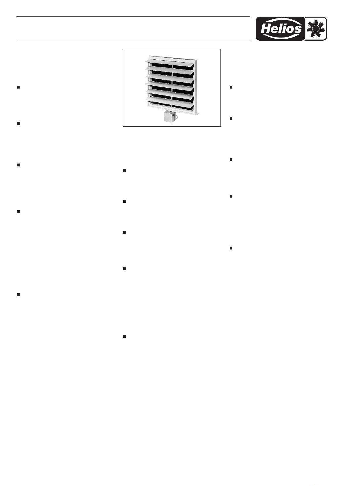
Außenwand-Verschlussklappe EVK 200-710 (elektrisch verstellbar)
Outwall electrical shutter EVK 200-710 (electrically operated)
Volet de fermeture EVK 200-710 (réglage électrique)
1
ONTAGE- UND BETRIEBSVORSCHRIFT
NR. 86 538
Zur Sicherstellung einer einwandfreien Funktion und
zur eigenen Sicherheit sind alle nachstehenden Vor-
schriften genau durchzulesen und zu beachten.
E PFANG
Sendung sofort bei Anlieferung auf Beschädigungen
und Typenrichtigkeit prüfen. Falls Schäden vorliegen,
umgehend Schadensmeldung unter Hinzuziehung des
Transportunternehmens veranlassen. Bei nicht fristge-
rechter Reklamation gehen evtl. Ansprüche verloren.
EINLAGERUNG
Der agerort muss erschütterungsfrei, wasserge-
schützt und frei von Temperaturschwankungen sein.
Schäden, deren Ursache in unsachgemäßem Trans-
port, Einlagerung oder Inbetriebnahme liegen, sind
nachweisbar und unterliegen nicht der Gewährlei-
stung.
EINSATZBEREICH
Die über einen Stellmotor verstellbare elektrische Au-
ßenwand Verschlussklappe EVK..., ist zur Abdeckung
von Zu- und Abluftöffnungen der Nennweite von 200
bis 710 mm in Räumen mit normaler oder leicht staub-
haltiger, wenig aggressiver und feuchter uft, im Be-
reich ihrer eistungskennlinie, geeignet. Sie verhindert
unerwünschte uftzu- und -abfuhr.
ELEKTRISCHER ANSCHLUSS
Vor allen Wartungs- und Installationsarbeiten
oder vor Öffnen des
Revisionsraumes
, muss das
Gerät allpolig vom Netz getrennt werden.
Der elektrische Anschluss darf nur von einer autor. Elek-
trofachkraft durchgeführt werden. Der
Anschluss erfolgt
nach Schaltplan SS-39 bzw. SS-73.
Die einschlägigen Sicherheitsvorschriften, Normen (wie
VDE 0100, VDE 0530 u. VDE 0700 sowie die TAB’s der
EVU’s u. UVV) sind einzuhalten. Die Netzspannung
muss mit den Angaben des Typenschildes übereinstim-
men.
Die Zuleitung ist so vorzunehmen, dass bei Wasser-
beaufschlagung kein Eindringen entlang der eitung er-
möglicht wird. eitung nie über scharfe Kanten führen.
ONTAGE
ontage und Wartungsarbeiten an der EVK,
dürfen nur durchgeführt werden, wenn die Ver-
schlussklappe allpolig vom Netz getrennt ist.
Die EVK... werden anschlussfertig mit ausgeführter
eitung 4 x 1,0 mm² (ohne Schutzleiter) geliefert.
Die Montage erfolgt mit dem Befestigungssatz (je 4
Schrauben und Dübel) über der Ab./ Zuluftöffnung an
der Außenwand. Befestigungsbohrungen typenab-
hängig aus der Maßzeichnung bzw. Tabelle entneh-
men. Bei der Montage ist auf eine ebene Auflage zur
Wand hin, zu achten.
Elektrischer Anschluss erfolgt nach Schaltplan SS-39
bzw. SS-73.
– Ansteuerung
Ader 1 = Klappe zu fahren (230V~)
Ader 2 = Klappe auf fahren (230V~)
Ader 3 = Signal Klappe auf (230V~, nur so lange
wie Ader 2 mit 230V~ beschaltet ist).
Ader 4 = N, Neutral- eiter
Die Ansteuerung einer Klappe bzw. bis zur Type 500,
kann mit einem Wechselschalter durchgeführt wer-
den. Die Einbindung in eine Steuerung mit Ventilator,
ist im Schaltschema SS-39 beispielhaft dargestellt.
Ab der Type 630 bzw. bei Steuerung mehrerer
EVK..., dürfen die Steuerdrähte Ader 1 und 2, nicht
miteinander verbunden werden (parallel). Hierfür
müssen die Steuereingänge über ein bauseits zu stel-
lendes Relais, getrennt voneinander angesteuert wer-
den. Beispiel im Schaltschema SS-73.
INSTALLATION AND OPERATING INSTRUCTIONS
NO 86 538
To ensure safety and correct installation please re-
ad the following instructions carefully before pro-
ceeding.
RECEIPT
Please check consignment immediately on receipt for
accuracy and damage. If damaged, please notify car-
rier immediately. Delay in notification may invalidate any
possible claim.
STORAGE
The storage area must be dry, free from vibrations and
temperature variations.
Damage due to transportation, storage or incorrect in-
stallation and operation lies outside warranty.
APPLICATION/USE
The outwall electrical shutter EVK.., that is adjustable
with a servo motor, is designed to cover NS 200 -
750 mm air intake or extract openings on internal or
external walls to prevent unintended air flow in the
system.
ELECTRICAL CONNECTION
All work must be carried out with the equip-
ment fully isolated from the power supply.
The electrical connections are to be carried out by a
qualified electrician in accordance with all relevant
safety regulations, national standards and norms. Wiring
according to wiring diagram SS-39 respectively SS-73.
The supply voltage must correspond to the figure
stated on the rating plate. The unit must be installed in
such a way that water cannot enter along the cable.
Do not lead the cable over any sharp edges and/or cor-
ners.
INSTALLATION
The front grille must only be installed when the
unit is fully isolated from the supply.
The types EVK... are delivered ready for installation
with a lead (4 x 1,0 mm² (without grounding con-
ductor). The installation is made by means of the en-
closed mounting kit (each 4 screws, 50 mm and do-
wel pins) to cover exhaust/intake air opening at the
external wall. See mounting holes, depending on the
type, from drawing and/or table on page 3 (dimensi-
on D and E) and mark them. Drill and then screw the
shutter on the wall. Pay attention to even support on
wall!
Wiring according to wiring diagram SS-39 and/or SS-
73.
- Control
Wire 1 = Close shutter (230V~)
Wire 2 = Open shutter (230V~)
Wire 3 = Signal shutter open (230V~,only as long
as wire 2 is connected with 230 V).
Wire 4 = N, Neutral conductor
The control of one shutter respectively till type 500
can be carried out by a changeover switch. The inte-
NOTICE D’INSTALLATION ET D’UTILISATION
NO. 86 538
Par mesure de sécurité, l’ensemble des prescripti-
ons qui suivent sont à lire attentivement et à res-
pecter!
RÉCEPTION
Dès réception vérifier l’état et la conformité du matériel
commandé. En cas d’avaries, faire les réclamations
d’usage auprès du transporteur.
Attention: Pas de remarques à temps, pas de recours!
STOCKAGE
e matériel est à stocker dans un endroit abrité de l’eau,
exempt de variations de température et de vibrations.
es dommages dus à de mauvaises conditions de
transport, à des stockages défectueux ou à une utilisa-
tion anormale sont sujets à vérification et contrôle et en-
traînent la suppression de notre garantie.
DO AINE D’UTILISATION
e volets de fermeture
électrique
EVK.. est prévue
pour un diamètre de gaine de 200 - 750 mm, soit pour
introduction, soit pour extraction d’air. Il peut être con-
trolé séparement par un commutateur ou en parallèle
avec un ventilateur.
BRANCHE ENT ÉLECTRIQUE
Tous les travaux doivent être effectués hors ten-
sion!
e branchement électrique doit être effectué par un
électricien qualifié. Raccordement selon schéma SS-39
ou SS-73. es consignes de sécurité ainsi que les nor-
mes standards nationales doivent être respectées. a
tension de réseau doit correspondre aux données de la
plaque signalétique moteur.
ONTAGE
Le volet électrique doit être mis impérative-
ment hors tension avant tous travaux d’entretien
et de montage.
es grilles EVK…sont livrées avec câble monté 4 x 1,0
mm² (sans conducteur de protection).
e montage s’effectue à l’aide du kit de fixation fourni
(4 vis et chevilles) par le côté entrée/sortie air, sur le
mur extérieur. es cotes des trous de fixation sont in-
diquées sur le plan et le tableau des caractéristiques.
a surface de contact du mur avec la grille doit être
rigoureusement plane.
Branchement électrique suivant le schéma SS-39 ou
SS-73.
– Commande
Fil 1 = Fermeture du volet (230V~)
Fil 2 = Ouverture du volet (230V~)
Fil 3 = Signal volet ouvert (230V~, pendant la
durée d’alimentation 230V~ sur Fil 2).
Fil 4 = N, neutre
es volets de taille inférieure ou égale à 500 peuvent
être commandés par un interrupteur va et vient. e
schéma de branchement SS-39 montre un exemple
d’intégration du volet dans la commande d’un venti-
lateur.
A partir du modèle EVK 630 et en cas de comman-
de simultanée de plusieurs volets, les fils 1 et 2 ne
peuvent plus être alimentés en direct ni en parallèle.
Il sera nécessaire de les commander via un con-
tacteur de puissance (fait du client), chaque fil étant
raccordé sur un contact dédié. Voir schéma SS-73.
e relais peut être commandé, entre autres par la
sortie 230V non régulée d’un variateur, par ex. type
MWS.., TSW..., TSD..., RDS... ou ESA/U 1, 3, et 5
(accessoires Helios).
e signal « volet ouvert » est fourni par le servomo-
teur. Il s’agit d’un signal de fin de course moteur et
non d’un signal d’ouverture totale du volet. Il est im-
portant de noter cette différence en cas d’intégration


