Helios AirPal-IVSS User manual
Interventionsschutz-Set
Tamper Protection Kit
AirPal-IVSS
für AirPal Standgeräte
for AirPal tower units
Helios Ventilatoren
MONTAGE- UND BETRIEBSVORSCHRIFT
INSTALLATION AND OPERATING INSTRUCTIONS EN
DE

1
DEDE
Interventionsschutz-Set AirPal-IVSS
Montage- und Betriebsvorschrift
1.1 Wichtige Informationen
Zur Sicherstellung einer einwandfreien Funktion und zur eigenen Sicherheit sind alle
nachstehenden Vorschriften genau durchzulesen und zu beachten. Nationale einschlägi-
gen Normen, Sicherheitsbestimmungen und Vorschriften (z.B. DIN EN VDE 0100) sowie
die TAB des EVUs sind unbedingt zu beachten und anzuwenden.
Die Bedienungsanleitung als Referenz am Gerät aufbewahren. Nach der Endmontage
muss dem Betreiber (Mieter/Eigentümer) das Dokument ausgehändigt werden.
1.2 Warn- und Sicherheitshinweise
Nebenstehendes Symbol ist ein sicherheitstechnischer Warnhinweis. Alle Sicher-
heitsvorschriften bzw. Symbole müssen unbedingt beachtet werden, damit jeg-
liche Gefahrensituation vermieden wird.
m GEFAHR
Warnung vor Gefahren, die bei Missachtung der Maßnahmen unmittelbar zu Tod oder
schweren Verletzungen führen.
m WARNUNG
Warnung vor Gefahren, die bei Missachtung der Maßnahmen zu Tod oder schweren Ver-
letzungen führen können.
m VORSICHT
Warnung vor Gefahren, die bei Missachtung der Maßnahmen zu Verletzungen führen können.
ACHTUNG
Warnung vor Gefahren, die bei Missachtung der Maßnahmen zu Sachschäden führen können.
1.3 Garantieansprüche – Haftungsausschluss
Wenn die nachfolgenden Ausführungen nicht beachtet werden, entfällt unsere Gewähr-
leistung. Gleiches gilt für Haftungsansprüche an den Hersteller. Der Gebrauch von Zu-
behörteilen, die nicht von Helios empfohlen oder angeboten werden, ist nicht statthaft.
Eventuell auftretende Schäden unterliegen nicht der Gewährleistung.
1.4 Sendungsannahme
Die Lieferung enthält das Interventionsschutz-Set AirPal-IVSS. Die Sendung ist sofort
bei Anlieferung auf Beschädigungen und Typenrichtigkeit zu prüfen. Falls Schäden vor-
liegen umgehend Schadensmeldung unter Hinzuziehung des Transportunternehmens
veranlassen. Bei nicht fristgerechter Reklamation gehen evtl. Ansprüche verloren.
1.5 Bestimmungsgemäße Verwendung
Einsetzbar für alle AirPal-Standgeräte. Bestehend aus einer Abdeckung mit Verriege-
lung, welche das unbefugte Verstellen der Lüftungsstufe verhindert, sowie aus einem
T-Griff mit integriertem Schloss, welcher in die Servicetür eingebaut werden kann und
so das unbefugte Öffnen des Geräts verhindert.
Ein bestimmungsfremder Einsatz ist nicht zulässig!
m Lebensgefahr
Der elektrische Anschluss des AirPal-Geräts muss bis zur Endmontage vollständig vom
Stromnetz getrennt sein.
KAPITEL 1
ALLGEMEINE
HINWEISE
m
mGEFAHR
mWARNUNG
mVORSICHT
ACHTUNG
ACHTUNG
KAPITEL 2
MONTAGE
mGEFAHR

2
DEDE
Interventionsschutz-Set AirPal-IVSS
Montage- und Betriebsvorschrift
2.1 Montage der Abdeckung
1. Packen Sie das Interventionsschutz-Set AirPal-IVSS aus und entnehmen Sie die
Abdeckung mit dem Plexiglasaufsatz.
2. Verwenden Sie den Schlüssel, um den Plexiglasaufsatz zu entriegeln und von der
Abdeckung zu entfernen.
3. Entfernen Sie die Schrauben an den Ecken des Bedienfelds.
Abb. 1
Abb. 2
Abb. 3

3
DEDE
Interventionsschutz-Set AirPal-IVSS
Montage- und Betriebsvorschrift
4. Nehmen Sie das Netzkabel und befestigen Sie es in der Kunststoff-Kabelklemme an
der Abdeckung.
5. Positionieren Sie die Abdeckung über das Bedienfeld. Die Schraubenlöcher sollten
auf gleicher Position liegen.
6. Zur Befestigung der Abdeckung nutzen Sie die zuvor entfernten Schrauben (Abb. 3).
7. Setzen Sie den Plexiglasaufsatz auf die Abdeckung und verwenden Sie den Schlüs-
sel, um den Plexiglasaufsatz auf der Abdeckung zu verriegeln (Abb. 1, Abb. 2).
Abb. 4
Abb. 5
Abb. 6

4
DEDE
Interventionsschutz-Set AirPal-IVSS
Montage- und Betriebsvorschrift
2.2 Anbringung des T-Griffs
2.2.1 Vorhandenen Verriegelungsmechanismus demontieren
Der vorhandene Verriegelungsmechanismus muss vor der T-Griff Montage entfernt wer-
den. Die Schritte zur Demontage sind unten dargestellt.
Es wird empfohlen den obersten Verriegelungsmechanismus durch den T-Griff zu
ersetzen.
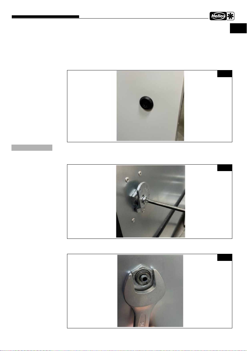
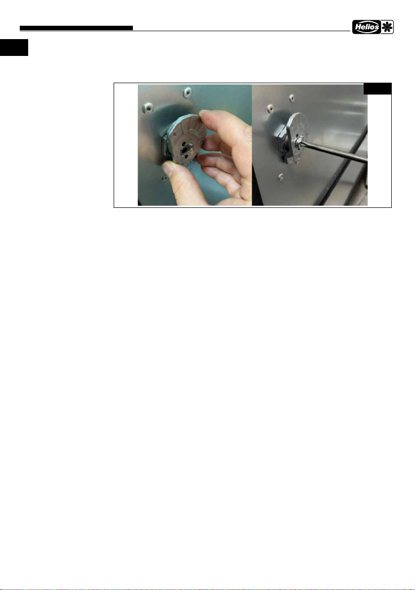
1. Entfernen Sie die Schraube und das Verschlussteil auf der Schlossrückseite mit einem
Schraubendreher.
2. Entfernen Sie die Mutter auf der Schlossrückseite mit einem Schraubenschlüssel.
Abb. 7
ACHTUNG
Abb. 8
Abb. 9
5
DEDE
Interventionsschutz-Set AirPal-IVSS
Montage- und Betriebsvorschrift
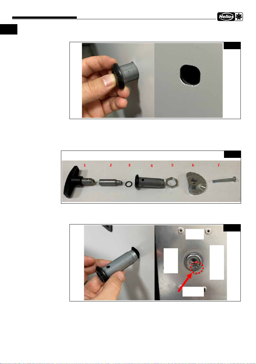
3. Ziehen Sie den Verriegelungsmechanismus an der Vorderseite der Einheit heraus.
2.2.2 Montage des T-Griffs
Nach der Demontage des vorhandenen Verriegelungsmechanismus wird der T-Griff wie
folgt montiert:
1. Bauen Sie den T-Griff auseinander (Abb. 11).
2. Nehmen Sie das Teil 4 (der Verriegelungskörper) und schieben es in das Loch an der
Gerätetür ein. Das Teil 4 muss in einer speziellen Position eingebaut werden (siehe
Abb. 12)!
Abb. 10
Abb. 11
Abb. 12
Oben
Tür-
seite
Unten
Scharnier-
seite

6
DEDE
Interventionsschutz-Set AirPal-IVSS
Montage- und Betriebsvorschrift
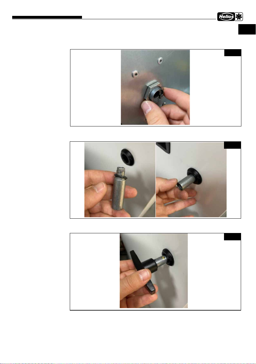
3. Setzen Sie das Teil 5 (die Gehäusemutter) auf und ziehen Sie sie mit einem
Schraubenschlüssel fest.
4. Schieben Sie das Teil 2 (den Verriegelungsmechanismus) mit dem Teil 3 (der O-
Ring) in den Verrriegelungskörper ein.
5. Setzen Sie das Teil 1 (der T-Griff) in das Teil 4 (der Verriegelungskörper) ein.
Abb. 13
Abb. 14
Abb. 15

7
DEDE
Interventionsschutz-Set AirPal-IVSS
Montage- und Betriebsvorschrift
6. Montieren Sie das Teil 6 (das Verschlussteil) mit dem Teil 7 (die Schraube).
Abb. 16

Tamper Protection Kit AirPal-IVSS
Installation and Operating Instructions
1
ENEN
1.1 Important information
In order to ensure complete and effective operation and for your own safety, all of the
following instructions should be read carefully and observed. The relevant national stan-
dards, safety regulations and instructions (e.g. DIN EN VDE 0100) as well as the technical
connection conditions of the energy supply company must be observed and applied.
Keep the operating instructions close to the unit for easy reference. After the final assem-
bly, the document must be issued to the operator (tenant/owner).
1.2 Warning and safety instructions
The adjacent symbol is a safety-relevant warning symbol. All safety regulations
and/or symbols must be absolutely adhered to, so that any dangerous situation
is avoided.
mDANGER
Indicates dangers which will directly result in death or serious injury if the safety instruction is
not followed.
m WARNING
Indicates dangers which will result in death or serious injury if the safety instruction is not
followed.
m CAUTION
Indicates dangers which can result in injuries if the safety instruction is not followed.
ATTENTION
Indicates dangers which can result in material damage if the safety instruction is not followed.
1.3 Warranty claims – Exclusion of liability
Our warranty shall not apply if the following instructions are not observed. The same
applies for liability claims against the manufacturer. The use of accessories which are
not recommended or offered by Helios is not permitted. Any damage that may occur is
not liable for warranty.
1.4 Receipt
The delivery contains the tamper protection kit AirPal-IVSS. Please check delivery
immediately on receipt for accuracy and damage. If damaged, please notify the carrier
immediately. In case of delayed notification, any possible claim may be void.
1.5 Intended use
Suitable for all AirPal tower units. Consists of a cover with a locking mechanism that
prevents any unauthorised adjustment of the ventilation level as well as a T-handle with
an integrated lock that can be installed in the service door and thus prevents the un-
authorised opening of the unit.
Any use other than the intended use is prohibited!
CHAPTER 1
GENERAL
INFORMATION
m
mDANGER
mWARNING
mCAUTION
ATTENTION
ATTENTION

2
ENEN
Tamper Protection Kit AirPal-IVSS
Installation and Operating Instructions
m Danger to life
The electrical connection of the AirPal unit must be fully isolated from the mains power sup-
ply until final assembly.
2.1 Cover assembly
1. Unpack the tamper protection kit AirPal-IVSS and remove the cover with the
plexiglass top.
2. Use the key to unlock the plexiglass top and remove it from the cover.
3. Remove the screws in the corners of the control panel.
CHAPTER 2
INSTALLATION
mDANGER
Fig.1
Fig.2
Fig.3

Tamper Protection Kit AirPal-IVSS
Installation and Operating Instructions
3
ENEN
4. Take the power cable and secure it in the plastic cable clamp on the cover.
5. Position the cover over the control panel. The screw holes should be in the same
position.
6. Use the previously removed screws (Fig.3) to attach the cover.
7. Place the plexiglass top on the cover and use the key to lock the plexiglass top on
the cover (Fig.1, Fig.2).
Fig.4
Fig.5
Fig.6
4
ENEN
Tamper Protection Kit AirPal-IVSS
Installation and Operating Instructions
2.2 Attaching the T-handle
2.2.1 Disassembling the existing locking mechanism
The existing locking mechanism must be removed before installing the T-handle. The
disassembly steps are shown below.
It is recommended to replace the top locking mechanism with the T-handle.
1. Remove the screw and locking part on the back of the lock with a screwdriver.
2. Remove the nut on the back of the lock with a spanner.
Fig.7
ATTENTION
Fig.8
Fig.9

Tamper Protection Kit AirPal-IVSS
Installation and Operating Instructions
5
ENEN 3. Pull out the locking mechanism on front side of the unit.
2.2.2 T-handle assembly
After disassembling existing locking mechanism, the T-handle is mounted as follows:
1. Disassemble the T-handle (Fig.11).
2. Take part 4 (the locking body) and insert it into the hole on the unit door. Part 4 must
be installed in a specific position (see Fig.12)!
Fig.10
Fig.11
Fig.12
6
ENEN
Tamper Protection Kit AirPal-IVSS
Installation and Operating Instructions
3. Place part 5 (the body nut) on and tighten it with a spanner.
4. Insert part 2 (the locking mechanism) with part 3 (O-ring) into the locking body.
5. Insert part 1 (the T-handle) into part 4 (the locking body).
Fig.13
Fig.14
Fig.15
Tamper Protection Kit AirPal-IVSS
Installation and Operating Instructions
7
ENEN
6. Mount part 6 (the locking part) with part 7 (the screw).
Fig.16

Als Referenz am Gerät griffbereit aufbewahren! Druckschrift-Nr.
Please keep this manual for reference with the unit! Print-No.
Conservez cette notice à proximité de l'appareil! No. Réf. 25 502-001/21-0101/V01/0621
Service und Information
DHELIOS Ventilatoren GmbH + Co KG · Lupfenstraße 8 · 78056 VS-Schwenningen F HELIOS Ventilateurs · Le Carré des Aviateurs · 157 av. Charles Floquet ·
CH HELIOS Ventilatoren AG · Tannstrasse 4 · 8112 Otelfingen 93155 Le Blanc Mesnil Cedex
AHELIOS Ventilatoren · Postfach 854 · Siemensstraße 15 · 6023 Innsbruck GB HELIOS Ventilation Systems Ltd. · 5 Crown Gate · Wyncolls Road ·
Severalls Industrial Park · Colchester · Essex · CO4 9HZ
www.heliosventilatoren.de
Table of contents
Languages:
Popular Protection Device manuals by other brands

Scorpion Power System
Scorpion Power System Tribunus 06-120A ESC user guide

Crye Precision
Crye Precision JPC SIDE PLATE POUCH SET MARITIME installation instructions

PROTRUSS
PROTRUSS CC230P user manual

Fahl
Fahl LARYVOX TAPE Instructions for use

Schörghofer & Frehe
Schörghofer & Frehe Plisse manual

Rion
Rion WS-15 instruction manual


