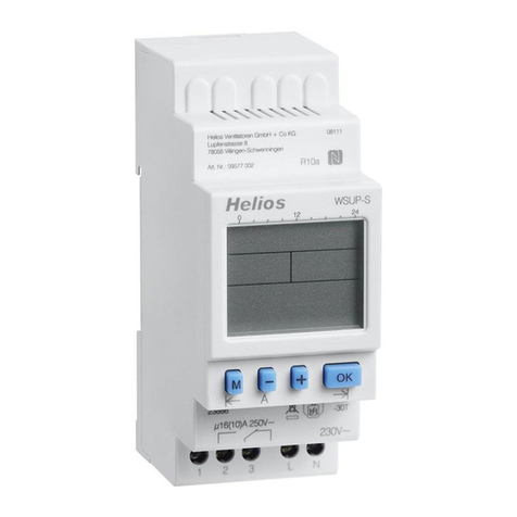
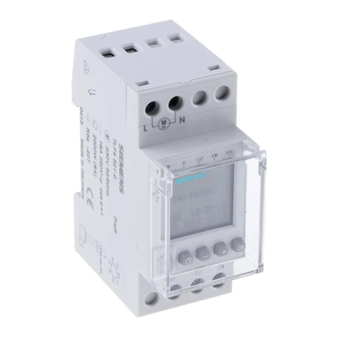
Helios ZLS-ZU 31 User manual

Elektronisches Zeitschaltuhr-Modul
Electronic Timer Module
ZLS-ZU 31
mit Tag- und Nachtumschaltung
with day/night switchover facility
Helios Ventilatoren
MONTAGE- UND BETRIEBSVORSCHRIFT
INSTALLATION AND OPERATING INSTRUCTIONS EN
DE

1
Elektronisches Zeitschaltuhr-Modul ZLS-ZU 31
Montage- und Betriebsvorschrift
1.0 Wichtige Informationen
Zur Sicherstellung einer einwandfreien Funktion und zur eigenen Sicherheit sind alle nachstehenden
Vorschriften genau durchzulesen und zu beachten. Der Elektroanschluss muss bis zur Endmontage allpolig
vom Netz getrennt werden! Die Montage- und Betriebsvorschrift als Referenz am Gerät aufbewahren.
Weitere wichtige Anschlusshinweise zum Zeitschaltuhr-Modul ZLS-ZU 31 sind in dem separat erhältlichen
Dokument „ZLS-DVEC – Schnellübersicht“ Nr. 91527.002 zu finden!
1.1 Warn- und Sicherheitshinweise
Nebenstehendes Symbol ist ein sicherheitstechnischer Warnhinweis. Alle Sicherheitsvorschriften bzw.
Symbole müssen unbedingt beachtet werden, damit jegliche Gefahrensituation vermieden wird.
1.2 Garantieansprüche – Haftungsausschluss
Wenn die nachfolgenden Ausführungen nicht beachtet werden, entfällt unsere Gewährleistung. Gleiches gilt für
Haftungsansprüche an den Hersteller.
Der Gebrauch von Zubehörteilen, die nicht von Helios empfohlen oder angeboten werden, ist nicht statthaft. Eventuell
auftretende Schäden unterliegen nicht der Gewährleistung.
1.3 Vorschriften – Richtlinien
Bei ordnungsgemäßer Installation und bestimmungsgemäßem Betrieb entspricht das Gerät den zum Zeitpunkt seiner
Herstellung gültigen Vorschriften und CE-Richtlinien.
1.4 Sendungsannahme
Die Sendung sofort bei Anlieferung auf Beschädigungen und Typenrichtigkeit prüfen. Falls Schäden vorliegen umge-
hend Schadensmeldung unter Hinzuziehung des Transportunternehmens veranlassen.
Bei nicht fristgerechter Reklamation gehen evtl. Ansprüche verloren.
1.5 Technische Daten
Spannung/Frequenz 1~, 230 V, 50 Hz
Nennstrom max. 0,03 A
Sollwertausgang (Esoll = max. 10 mA)
Schutzart IP40
Maße in mm b = 200, h = 150, t = 75
Type ZLS-ZU 31 Best.-Nr. 8388
2.0 Einsatzbereich
Das elektronische Zeitschaltuhr-Modul ZLS-ZU 31 ist zur Einstellung von automatischen Schaltzeiten für Tag-/Nacht-
Betrieb vorgesehen. Es erlaubt den parallelen Betrieb von maximal 31 DVEC-Dachventilatoren. Das Zeitschaltuhr-
Modul wird über den Wippen-Hauptschalter in Betrieb gesetzt. Die Tag- und Nachtumschaltung erfolgt über die Ein-
stellungen im Display (siehe beiliegende Bedienungsanleitung zur Zeitschaltuhr).
Die Geräte sind für den Einsatz bei Umgebungsbedingungen mit üblichen Verunreinigungen vorgesehen.
Einsatz und Betrieb nur entsprechend dieser Montage- und Betriebsvorschrift.
Ein bestimmungsfremder Einsatz ist nicht zulässig!
2.1 Sicherheit
- Wartungs- und Installationsarbeiten dürfen nur von einer autorisierten Elektrofachkraft vorgenommen wer-
den.
- Das Gerät darf nur mit der auf dem Typenschild angegebenen Nennspannung betrieben werden.
- Technische Daten auf Typenschild unbedingt beachten.
- Die auf dem Typenschild angegebene Schutzart gilt nur bei bestimmungsgemäßen Einbau gemäß dieser
Montage- und Betriebsvorschrift.
2.2 Elektrischer Anschluss
Vor allen Wartungs- und Installationsarbeiten oder vor Öffnen des Schaltraumes ist das Gerät allpolig vom
Netz zu trennen! Der elektrische Anschluss darf nur von einer autorisierten Elektrofachkraft entsprechend den
nachstehenden Anschlussplänen (Seite 7) ausgeführt werden. Die einschlägigen Sicherheitsvorschriften, Normen
(wie VDE 0100, VDE 0530 und VDE 0700 sowie die TAB‘s der EVU‘s und UVV) sind einzuhalten. Netzspannung und
Frequenz müssen mit den Angaben des Geräteleistungsschildes übereinstimmen.
3.0 Inbetriebnahme
Folgende Kontrollarbeiten sind auszuführen:
– Bestimmungsgemäßen Einsatz überprüfen
– Netzspannung mit Leistungsschild vergleichen
– Stromaufnahme mit Leistungsschildangaben vergleichen
– Zeitschaltuhr auf solide Befestigung prüfen
– Abdichtung des Anschlusskabels und festen Klemmsitz der Adern prüfen
– Die Zeitschaltuhr ist bei Anschluss im Stromsparmodus. Die Uhrzeit und das Datum laufen in der Werkseinstellung.
Die Anzeige „Doppelpunkt“ blinkt. Beliebige Taste drücken um die Zeitschaltuhr zu aktivieren.
– Sind mehrere DVEC-Ventialtoren mit einer ZLS-ZU 31 angeschlossen, muss im Menü der Parameter „Adresse“
mit einem ZLS-BDT oder ZLS-IF inkl. Laptop geändert werden. Hierzu „ZLS-DVEC Schnellanleitung“ (Abschnitt 04,
Seite 6) beachten.
Die Tasten dürfen nicht mit metallischen, spitzen Gegenständen (z. B. Nadel) bedient werden!
ALLGEMEINE MONTAGE-
UND BETRIEBSHINWEISE
m
HINWEIS +
WICHTIG +
ACHTUNG m

2
Elektronisches Zeitschaltuhr-Modul ZLS-ZU 31
Montage- und Betriebsvorschrift
4.0 Abmessungen (Maße in mm)
150
200
75
Abb.1
Prinzip für ZLS-DVEC Anschluss
LN
18VEsoll GND
U3 10V
RS
ARS
BRS
ARS
B
EsollGND
U3
GND
U3
An
ÖG
GS EN
+
Motor Anschluss
12345
6789
230V~
Sensor Sollwert
Relais
Alarm
Freigabe
RS 485
SUB-D 9, Buchse
+18VDC
+0-10VDC
-
+10VDC
+0-10VDC
-
10VDC
bis
230VAC
EN
-
WS
1
2
3 4 5 6
7
1
2
3
4
5
6
7
WS-
Wartungsschalter
RS 485
Schnittstelle
Sensor
Sollwerteingang
0-10VDC
Relais Ausgang
(bei Alarm G-S
geschlossen)
Eingang für
Startfreigabe
Anschluss
EC-Motor
1
2
3
4
5
6
Anschluss mit ZLS-ZU 31 Zeitschaltuhr
LN
18VEsoll GND
U3 10V
RS
ARS
BRS
ARS
B
EsollGND
U3
GND
U3
An
ÖG
GS EN
+
Motor Anschluss
12345
6789
230V~
RS 485
SUB-D 9, Buchse
EN
-
WS
1
2
3
4
5
6
Esoll, UIT
Esoll, IN
EN, IN
EN, UIT
GND
GND
+10V
L
N
L
N230V~
max. 30 weitere
ZLS-DVEC
ZLS-ZU 31 Freigabe
Ein/Aus
R1-Drehzahl 2
R2-Drehzahl 1
1
2
N
L
92791 SS-753 18.02.04
br
sw
bl
In der Schnellübersicht /
Kurzanleitung zum Gerät,
finden sich weitere
Anschlussbeispiele.
Schaltplan SS-753
Anschluss der Zeitschaltuhr
ZLS-ZU 31 mit Dachventilator
ZLS-DVEC

1
Electronic Timer Module ZLS-ZU 31
Installation and Operating Instructions
1.0 Important information
In order to ensure complete and effective operation and for your own safety, all of the following instructions should
be read carefully and observed. The electrical connection must be fully isolated from the mains power supply un-
til final assembly! Please keep the installation and operating instructions for reference with the unit.
Further important connection instructions for the timer module ZLS-ZU 31 can be found in the separate docu-
ment “ZLS-DVEC – quick overview” No. 91527.002!
1.1 Warning and safety instructions
The adjacent symbol is a safety-relevant warning symbol. All safety regulations and/or symbols must be abso-
lutely adhered to, so that any dangerous situations are avoided.
1.2 Warranty claims – Exclusion of liability
Our warranty shall not apply if the following instructions are not observed. The same applies for liability claims against
the manufacturer.
The use of accessories, which are not recommended or offered by Helios, is not permitted. Any damage that may
occur is not liable for warranty.
1.3 Regulations – Guidelines
If the product is installed correctly and used to its intended purpose, it conforms to all applicable regulations and EC
guidelines at its date of manufacture.
1.4 Receipt
Please check delivery immediately on receipt for accuracy and damage. If damaged, please notify the carrier immedia-
tely.
In case of delayed notification, any possible claim may be void.
1.5 Technical data
Voltage/frequency 1~, 230 V, 50 Hz
Nominal current max. 0.03 A
Setpoint output (Esoll = max. 10 mA)
Protection category IP40
Dimensions in mm w = 200, h = 150, d = 75
Type ZLS-ZU 31 Ref. no. 8388
2.0 Area of application
The electronic timer module ZLS-ZU 31 is designed to set automatic switching times for day/night operation. It enables
the parallel operation of maximum 31 DVEC roof fans. The timer module is operated via the main rocker switch. The
day/night switchover is carried out via the settings on the display (see attached operating instructions for timer).
The units are designed for use in ambient conditions with common contaminants.
Application and operation only in compliance with these installation and operating instructions.
Any use other than the intended use is prohibited!
2.1 Safety
- Maintenance and installation work may only be carried out by an authorised electrician.
- The unit may only be operated with the nominal voltage specified on the type plate.
- The technical data on the type plate must always be observed.
- The protection category specified on the type plate shall only apply if the unit is installed according to its intended use
pursuant to these installation and operating instructions.
2.2 Electrical connection
The unit must be fully isolated from the mains power supply before all maintenance and installation work or
opening the terminal compartment! The electrical connection may only be carried out by an authorised
electrician according to the following wiring diagrams (page 7). The relevant safety regulations and standards must
be observed (e.g. VDE 0100, VDE 0530 and VDE 0700 and the technical connection regulations of the energy supply
company). The mains voltage and frequency must correspond to the details on the unit rating plate.
3.0 Commissioning
The following checks must be carried out:
– Check designated use of unit
– Compare mains voltage to rating plate data
– Compare power consumption to rating plate data
– Check timer for solid mounting
– Check the waterproofing of the connection cable and tight clamping of the strands
– The timer is in power saving mode upon connection. The time and date are set to factory settings.
The “colon” display will flash. Press any key to activate the timer.
– If multiple DVEC fans are connected to the ZLS-ZU 31, the “address” parameter in the menu must be changed to a
ZLS-BDT or ZLS-IF incl. laptop. In this respect, read the “ZLS-DVEC quick guide” (section 04, page 6).
The keys must not be operated with metallic, sharp objects (e.g. needle)!
GENERAL INSTALLATION
AND OPERATING
INSTRUCTIONS
m
NOTE +
IMPORTANT +
ATTENTION m

Electronic Timer Module ZLS-ZU 31
Installation and Operating Instructions
4.0 Dimensions (in mm)
150
200
75
Fig.1
Prinzip für ZLS-DVEC Anschluss
LN
18VEsoll GND
U3 10V
RS
ARS
BRS
ARS
B
EsollGND
U3
GND
U3
An
ÖG
GS EN
+
Motor Anschluss
12345
6789
230V~
Sensor Sollwert
Relais
Alarm
Freigabe
RS 485
SUB-D 9, Buchse
+18VDC
+0-10VDC
-
+10VDC
+0-10VDC
-
10VDC
bis
230VAC
EN
-
WS
1
2
3 4 5 6
7
1
2
3
4
5
6
7
WS-
Wartungsschalter
RS 485
Schnittstelle
Sensor
Sollwerteingang
0-10VDC
Relais Ausgang
(bei Alarm G-S
geschlossen)
Eingang für
Startfreigabe
Anschluss
EC-Motor
1
2
3
4
5
6
Anschluss mit ZLS-ZU 31 Zeitschaltuhr
LN
18VEsoll GND
U3 10V
RS
ARS
BRS
ARS
B
EsollGND
U3
GND
U3
An
ÖG
GS EN
+
Motor Anschluss
12345
6789
230V~
RS 485
SUB-D 9, Buchse
EN
-
WS
1
2
3
4
5
6
Esoll, UIT
Esoll, IN
EN, IN
EN, UIT
GND
GND
+10V
L
N
L
N230V~
max. 30 weitere
ZLS-DVEC
ZLS-ZU 31 Freigabe
Ein/Aus
R1-Drehzahl 2
R2-Drehzahl 1
1
2
N
L
92791 SS-753 18.02.04
br
sw
bl
In der Schnellübersicht /
Kurzanleitung zum Gerät,
finden sich weitere
Anschlussbeispiele.
Wiring diagram SS-753
Connection of timer ZLS-ZU 31
to roof fan ZLS-DVEC
Connection principle for ZLS-DVEC
Setpoint
Relay
alarm
Release
10VDC
up to
230VAC
Motor connection
maintenance switch
interface
Setpoint input
Relay output
(for alarm G-S
closed)
Input for
start release
Connection
EC motor
Connection to ZLS-ZU 31 timer
connector
Release
on/off
R1 speed 2
R2 speed 1 Further connection options can
be found in the quick overview /
quick guide for the unit
max. 30 additional
ZLS-DVEC
Motor connection
connector
2

Electronic Timer Module ZLS-ZU 31
Installation and Operating Instructions

Electronic Timer Module ZLS-ZU 31
Installation and Operating Instructions

Als Referenz am Gerät griffbereit aufbewahren! Druckschrift-Nr.
Please keep this manual for reference with the unit! Print-No.:
Garder cette notice à proximité de l’unité ! N° d’impression 86 383-001/1117
Service und Information
DHELIOS Ventilatoren GmbH + Co KG · Lupfenstraße 8 · 78056 VS-Schwenningen FHELIOS Ventilateurs · Le Carré des Aviateurs · 157 av. Charles Floquet · 93155 Le Blanc Mesnil Cedex
CH HELIOS Ventilatoren AG · Tannstrasse 4 · 8112 Otelfingen GB HELIOS Ventilation Systems Ltd. · 5 Crown Gate · Wyncolls Road · Severalls Industrial Park ·
AHELIOS Ventilatoren · Postfach 854 · Siemensstraße 15 · 6023 Innsbruck Colchester · Essex · CO4 9HZ
www.heliosventilatoren.de
D.20100401-0913
Table of contents
Languages:
Other Helios Timer manuals

