HELIX H905 User manual

ASSEMBLY MANUAL H905
Please read carefuly before using.
Aerobic Lateral Trainer
helix manuals_Helix H901 - May 2012 01/06/2012 10:38 Page 1

helix manuals_Helix H901 - May 2012 01/06/2012 10:38 Page 2

- 2 -
1/ IMPORTANT SAFETY INFORMATION
IMPORTANT SAFETY PRECAUTIONS
1. Read the OWNER'S OPERATING MANUAL and all accompanying literature and follow it carefully
before using your machine.
2. Inspect your exercise machine prior to exercising to ensure that all nuts and bolts are fully tightened before
each use.
3. Most exercise equipment is not recommended for small children. Children should not use the machine
unless they are under adult supervision.
4. Exercise equipment has moving parts. In the interest of safety, keep others, especially children, at a safe
distance while exercising.
5. Warm up 5 to 10 minutes before each workout and cool down 5 to 10 minutes afterward. This allows your
heart rate to gradually increase and decrease and will help prevent straining muscles.
6. Never hold your breath while exercising. Breathing should remain at a normal rate in conjunction with the
level of exercise being performed.
7. Rest adequately between workouts. Muscles tone and develop during these rest periods. Beginners should
work out twice a week and increase gradually to 4 or 5 times per week.
8. Remove all jewelry, including rings, chains and pins before commencing exercise.
9. Always wear suitable clothing and footwear during exercise. Do not wear loose fitting clothing that could
become entangled with the moving parts of your exercise machine.
10. This machine is intended for household use only. It is not designed for commercial use.
IMPORTANT!!! THE MAXIMUM RECOMMENDED WEIGHT CAPACITY FOR YOUR Helix is
130Kg (286 lbs.) per user.
WARNING: Before commencing with any exercise program, please consult your family physician.
If at any time during exercise you feel faint, dizzy or experience pain, stop and consult your family
physician. In the event any of the above mentioned warnings are breached by the consumer, the
manufacturer may use same as a defense to any claim for injuries, damage or loss. The above warnings
are in no way intended to limit or modify the consumer's remedies for breach of warranties pursuant
to applicable Federal and State Laws of Regulations. They are being supplied strictly to ensure the
safety of the individuals using this product.
The Surgeon General
has determined that
lack of physical activity is
detrimental to your health.
!
THIS OWNER’S MANUAL CONTAINS ASSEMBLY, OPERATION, MAINTENANCE AND SAFETY
INFORMATION. IN THE INTEREST OF SAFETY, PLEASE MAKE CERTAIN THAT YOU READ AND
UNDERSTAND ALL THE INFORMATION BELOW.
helix manuals_Helix H901 - May 2012 01/06/2012 10:38 Page 3

The parts required for each step of the assembly
process are sorted by step in individual zip bags
as shown left. Each step has required parts and
each of those parts is included with the bag
printed with the assembly step.
It is recommended that these parts not be
removed from the individual bags until each step
of the process to avoid mixing up or confusing
parts.
If you find that you are missing parts or the bag
for a step is missing, please contact Helix or
your dealer to receive those items. You can refer
to the parts by the “step number” for ease of
description.
- 3 -
TABLE OF CONTENTS
1 IMPORTANT SAFETY INFORMATION 2
Important Safety Precautions 2
Weight Limit Capacities 2
Warning 2
2 BEFORE YOU BEGIN 3-4
Parts Bags for ‘step by step’ assembly 3
Unpacking Information 4
Pre-Assembly Check List and Drawing 4
3 ASSEMBLY 5-10
4 GETTING STARTED 11
Computer Instructions 11-13
5 CUSTOMER INFORMATION
Customer Service back cover
READ ALL INSTRUCTIONS BEFORE USING
2/ PARTS BAGS FOR ‘STEP BY STEP’ ASSEMBLY
helix manuals_Helix H901 - May 2012 01/06/2012 10:38 Page 4
- 4 -
2/ BEFORE YOUR BEGIN
IMPORTANT: Read all instructions carefully. Assemble the Helix in accordance with the steps in the manual. All
tools required for assembly are included with your Helix. Lay out all parts on the floor. Make sure that you have all
the parts listed below before beginning assembly. In case of a discrepancy, please contact our Customer Service
Department at the email address or customer service number listed on the back page of this Owner’s Manual.
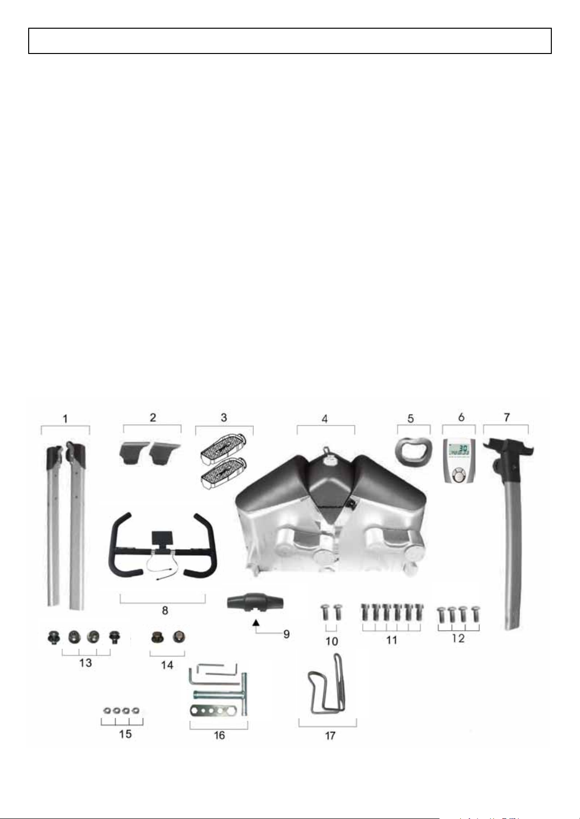
PRE-ASSEMBLY CHECK LIST
Note:
Some parts may be factory pre-assembled.
Item # Description Qty
1 LEFT AND RIGHT FRAME LEGS 2
2 END CAPS FOR FRAME LEGS 2
3 PEDAL FRAME AND COVERS 2
4 MAIN FRAME 1
5 RUBBER CIRCLE FOR UPRIGHT 1
6 COMPUTER 1
7. CENTER UPRIGHT TUBE 1
8. HANDLEBAR 1
9. TOP COVER 1
Item #Description Qty
10. WATER BOTTLE HOLDER SCREWS 2
11. PEDAL FRAME BOLTS 6
12. COMPUTER BOLTS 4
13. ALLEN HEAD UPRIGHT BOLTS 4
14. HEX HEAD UPRIGHT BOLTS 2
15. HANDLEBAR NUTS 4
16. ASSEMBLY TOOLS 5
17. WATER BOTTLE HOLDER 1
helix manuals_Helix H901 - May 2012 01/06/2012 10:38 Page 5

- 5 -
3/ ASSEMBLY
STEP 1:
Put the product on the floor and remove the top box cover to reveal the Helix as show above. Where the box
corners are printed “OPEN”, cut or tear the box and separate these corners. Lay the sides flat to the floor
IMPORTANT:
Do not remove the
Helix from the box
bottom until further
instructed later in
this assembly
manual.
STEP 2:
Attach the End Caps (2) to the Left and Right Frame Legs. These caps are not specific to either side. They fit on
left or right. If the Helix is not stable on the floor, turn the adjuster on the front end cap to raise or lower the height.
STEP 3:
Each Left and Right Frame Legs are marked “L” and “R” with a sticker. While facing the Helix, place the left
left on the left side of the machine and the right leg on the right side of the machine.
Insert the Frame Leg assembly bolts into the lefts and secure using the “T” wrench as shown. Tighten these
bolts firmly.
IT IS VERY IMPORTANT TO MAKE SURE THAT THE LEFT AND RIGHT FRAME LEGS ARE ON
THE CORRECT SIDE OR THE HELIX WILL NOT ROLL PROPERLY
1
2
3
Remove all parts from the box leaving just the main body of the machine on the bottom of the box.
remove all patrs from their plastic bags and organise the floor beside the Helix
15
helix manuals_Helix H901 - May 2012 01/06/2012 10:38 Page 6
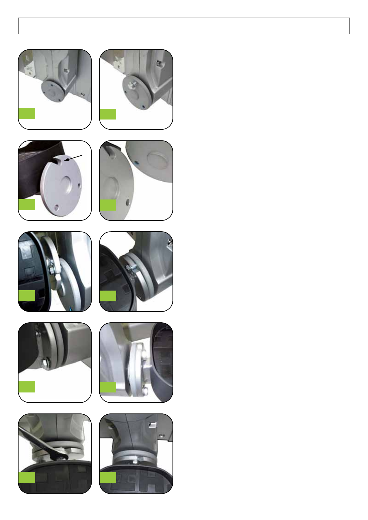
3/ ASSEMBLY - PEDALS
STEP 4:
Using the 6 Hex head bolts and washers from STEP 4
Plastic Parts Bag, install one bolt and one washer in the
top bolt of the plate as shown in Figure #5.
On the Pedal assembly make note of the slot in the
round disk as shown in Figure #6.
This slot is used to slide onto the bolt that you installed
in the round disk on the crank arm. Slide the slot over
the bolt as shown in Figure #8 . Be sure that the washer
is on the side of the bolt head and not between the two
connecting parts.
Turn the Pedal Assembly to align the two round plates
as shown in Figure #9
Next install a hex head bolt and washer on the right side
of the disk as shown in Figure #10. Repeat this again on
the other side of the disk as shown in Figure #11. There
will be a total of three bolts installed.
Note that one round disk has a protrusion and one has
an indentation as shown in Figure #7. These should fit
together evenly when assembled. Do not fully tighten
the hex head bolts until you are sure these two parts are
aligned. Then fully tighten the bolts with a Wrench as
shown in Figure #12.
Repeat the process for the 2nd pedal assembly.
45
67
89
10 11
12 13
- 6 -
Slot
helix manuals_Helix H901 - May 2012 01/06/2012 10:38 Page 7
- 7 -
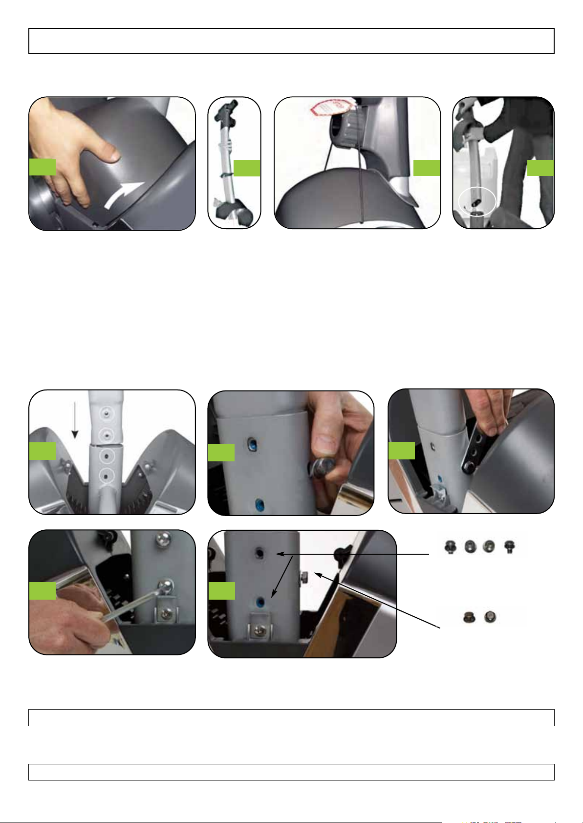
3/ ASSEMBLY - CENTER UPRIGHT TUBE
STEP 6:
Slide the upright tube into the frame as shown in Figure #4 & Figure #5 above. When fully installed first install
the two Hex Head bolts (Step 6 Plastic bag ) on either side of the upright as shown in Figure #6 & Figure #7
Do not fully tighten these bolts at this time.
STEP 7:
Take 4 Allen Head Bolts ( Step 7 Plastic Bag) and install these four bolts as shown in Figure #8 and Figure #9
Now fully tighten all 6 of these bolts.
34
12
Removeable
Cover
8
67
5
9
Allen Head Bolts
Front and back
Hex Head Bolts
Left and right of post
Remove the Center Dome Cover by
pressing in at the bottom on both
sides and lifting off of the Helix. (See
Figure #1) above.
Holding the Center Upright Tube as
shown in Figure #2, first slide on the
Rubber Circle for Upright. The side
of the Rubber Circle that has a minor
indentation should be positioned
toward the back of the Center
Upright Tube.
The back can be determined by the
opposite side of the Tension
Adjustment Knob. After sliding on
the Rubber Circle, then slide on the
‘Removeable Cover’ The cover
should be installed with the hole
toward the back side of the Upright
so that the majority of the cover sits
on the front of the Center Upright
Tube. (See Figure #2)
Slide the cover up as shown in
Figure #3 and pull the elastic band
around the tension knob to hold the
cover in place.This allows the cover
to be out of the way for the bolt
assembly of the Center Upright Tube
STEP 5:
helix manuals_Helix H901 - May 2012 01/06/2012 10:38 Page 8

- 8 -
3/ ASSEMBLY - CABLES
STEP 8:
Before beginning to connect the cables, turn the tension dial
on the front of the Center Upright Tube to the right as far as
it can go. This is level 8 on the dial. This action will extend
the cable at the bottom of the Center Upright Tube to make it
easier to insert into the receiving cable. See Figure #1.
Take the cable that extends at the bottom of the Center
Upright Tube (as shown in Figure #2) and attach it to the
cable that is fixed to the main frame. (See Figure #2) The
inset image of Figure #2 shows how to connect the two
cables. After connecting as shown in Figure #2, move the
lower cable bracket into place as shown in Figure #3 and in
more detail in the insert Figure #3a.
Next, turn the Tension adjustment knob all the way to the
left; to level 1. This should release the tension on the black
plastic “sleeve” that is surrounding the cable as shown in
Figure #4. If the adjustment has not completely loosened the
tension on the sleeve, pull up on the top cable to release this
plastic “sleeve”.
Remove the black plastic sleeve as shown in Figure #4 by
pulling it off of the cable . The black “sleeve’ has a cut in one
side to allow removal. Once you have removed the black
“sleeve”, return the tension control all the way to the right to
level 8 and then back to the left to level 1. This will confirm
the connection is properly made and you will see both cables
move together.
STEP 9:
Now connect the two electrical wires as shown in Figure #5.
They are fit together only one way . If they are not
connecting easily, turn one of the connectors to find the
correct position to attach these two connectors. When
properly connected they should “snap” together.
The connectors should now look as they do in Figure #7.
1
2
3
4
5 6 7
3a
helix manuals_Helix H901 - May 2012 01/06/2012 10:39 Page 9
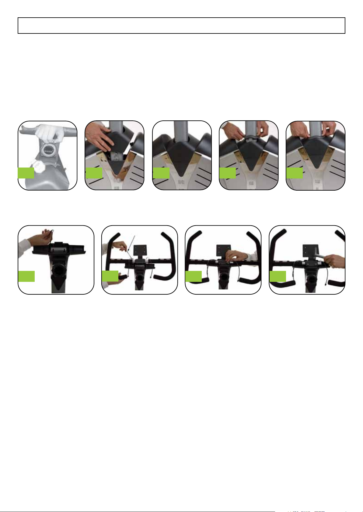
3/ ASSEMBLY - COVER AND HANDLE BARS
STEP 10:
Remove elastic cord from around the tension adjuster knob and then cut the cord to remove from the cover.
Slide the cover down to the bottom of the center upright tube and fit the tabs into the holds in the lower plastic
housing to fit snuggly in place as shown. Apply only gentle pressure to fit the tabs and the cover in place.
Slide the rubber circle down the center upright tube and push into place as shown.
FIXING THE HANDLE BARS
STEP 11:
a. The Center Upright Tube has a plastic cover at the top. On the left side, you will notice a wire.
(See Figure #6 above.). Make sure to place this over the back of the plastic lower cover so that when you
place the handle bars on the bolts, the wire is behind the handle bars.
b. Place handle bars on top of cover and align holes in bracket with the bolts protruding from the plastic
section. While placing the handle bars on the bolts, hold the wire (as mentioned above) to the back to avoid
being caught under the handle bars. (See Figure #7 above.)
c. Install 4 Nuts onto bolts and secure with T-Wrench (include in tools). Tighten firmly.
1 2 3 4 5
- 9 -
6789
helix manuals_Helix H901 - May 2012 01/06/2012 10:39 Page 10

STEP 12:
a. There should now be 3 wires. two coming from the handle bars and one that you held from the upright
when installing the handle bars. Hold all three wires together as shown in Figure #1 above.
b. Take Top Cover (part #9) and position with the notch in the rear to allow wires to come out.
See arrow in Figure #2.
c. Place plastic cover top onto the matching lower cover while making sure the wires are held through the
notch. (See Figure #3)
d. Gently snap the top cover onto the lower cover until all edges are flush. Gentle but firm pressure is required
to snap the two covers together. (See Figure #4) for method to press parts together.
See Figure #5 for final fit with wires in hand
WATER BOTTLE HOLDER INSTALLATION
STEP 13:
Find the two bolt holes with bolts pre-installed in the Center Upright Post and remove those bolts (Figure #1)
Once bolts holes are empty (Figure #2) hold the water bottle holder up to the post as shown and install a bolt in
the lower hole in the water bottle holder bracket (Figure #3) and through to the lower bolt hole on the upright.
Do not tighten at this time.
Tilt the water bottle holder upright to align the top hole in the bracket with the top hole on the center upright
post. Install a 2nd bolt into that hole and then tighten with the allen key as shown in Figure #4.
- 10 -
3/ ASSEMBLY - COVER AND HANDLE BARS
1 2 3 4 5
1234
helix manuals_Helix H901 - May 2012 01/06/2012 10:39 Page 11
COMPUTER INSTALLATION
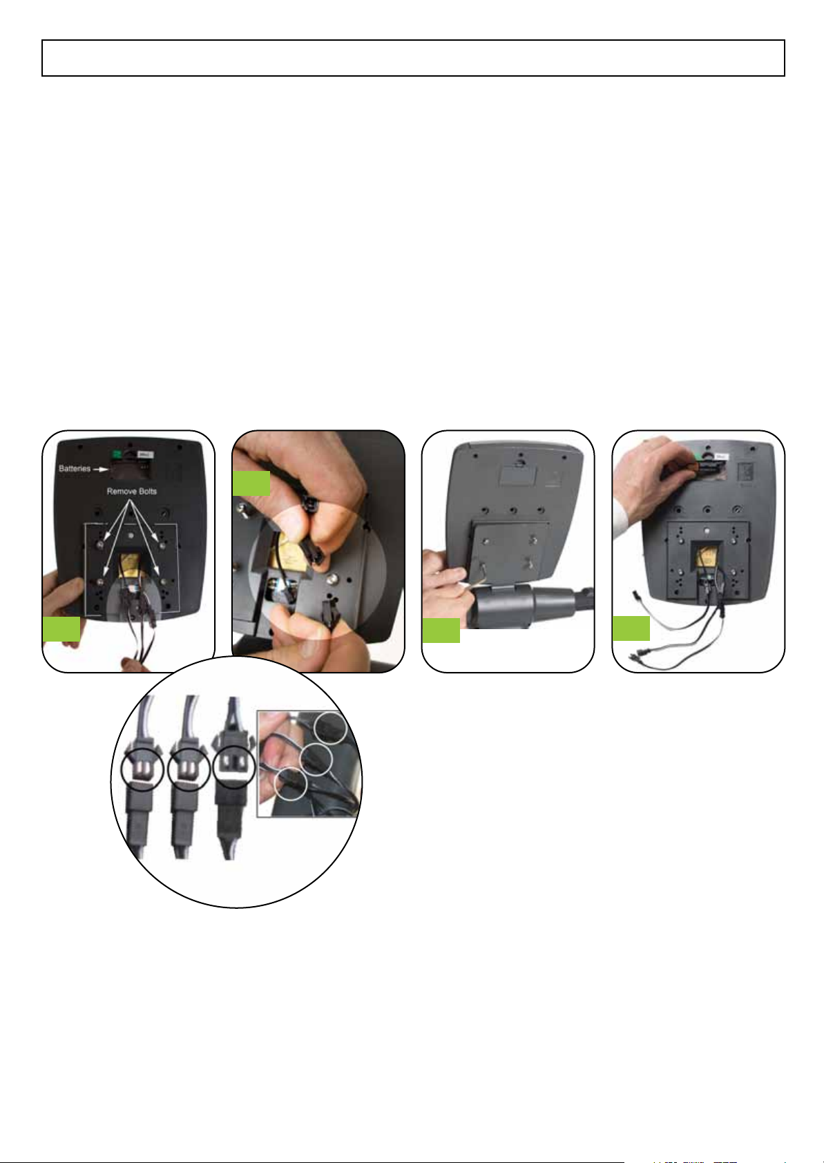
STEP 14:
Prepare Computer for installation. (See Figure #1). Remove 4 bolts and extend 3 wires from the back of the
computer. Do not install batteries in holder at this time. Note square ridge that will match up with metal
computer bracket on handlebars.
Connect the three wires from the handle bars to the three wires on the computer. These wires should snap
together easily. Do not force. Two wires are the same and it won't matter which is going to which wire. The 3rd
wire is different and can only connect to each other. (See Figure #2)
Carefully tuck the extra wire into the hole in the back of the computer and/or into the plastic cover to allow the
computer to be placed on the metal bracket. If the wires are too long, the extension wires can be disconnected to
shorten the length. This will not effect the function. (See Figure #2) highlight section.
Use 4 computer bolts to secure computer to brackets. Tighten firmly but Do not over tighten.
(See Figure #3)
Install 2 AA Batteries (included in Computer box) into the computer and replace cover.
- 11 -
3/ ASSEMBLY - COMPUTER
1
2
34
helix manuals_Helix H901 - May 2012 01/06/2012 10:39 Page 12
- 12 -
4/ GETTING STARTED - COMPUTER
A. WHEN DISPLAY IS ACTIVATED THE FOLLOWING WILL DISPLAY
Temperature Range (32~99 ) (0~60 )
Calendar Format 1900/1/1~2006/1/1~2099/12/31
Clock Format 24 HOURS / 0:00~23:59
B. FUNCTIONS
SCAN: When Scan is indicated on the screen, the Main display will change every 6 seconds.
It will change to display as follows.
SCANÔRPM /SPEEDÔTIMEÔDISTANCEÔCALORIESÔPULSEÔSCAN.
FUNCTION VALUE DISPLAY VALUE AVAILABLE SETTING INCREMENTS
Speed (Kilometers or Miles) 0.0 to 99.9 None None
RPM Up to 999 None None
Time Up to 99:59 Minutes Up to 99:00 Minutes 1 minute
Distance 0 to 99 KPH/MPH 0.00 to 99.00 KPH/MPH 0.50
Calories Up to 9999 10 to 9990 10 calories
Pulse - BPM (beats per minute) 30 to 240 bpm 30 to 240 bpm 1 bpm
C. INITIAL START UP
After installing the batteries, the computer will beep an extended sound and the LCD will fully light 2 seconds as a
test. The computer will then be ready for adjusting settings.
D. SETTING THE TIME & DATE:
Once the computer has initialized, it will automatically be ready to set the current time and date.
Please note: If no action is taken for 30 seconds, it will store the default time and date and be ready to function.
Setting the time and date are not required for proper computer operation.
After the computer initializes, the year will be flashing first. Change the year by rotating the dial clockwise or
counterclockwise until the year is correct. When the correct year is showing, press “Enter” in the center of the dial.
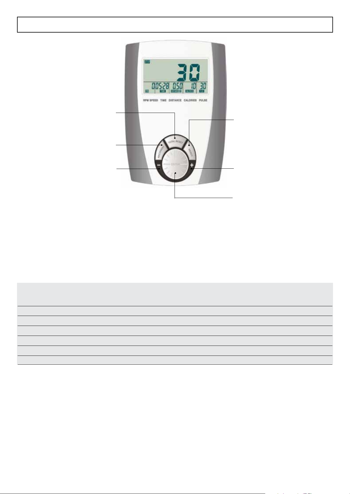
RESET KEY
Press key to reset function value to 0
for reset.
UP-Increase function value.
ENTER KEY & Knob
Press key to select function and confirm
setting value.
TOTAL RESET KEY
Press to total reset and come back initial
setting mode. ( set CLOCK /
CALENDAR / TIME)
RECOVERY KEY
Measure user’s recovery level.
DOWN-Decrease function value.
helix manuals_Helix H901 - May 2012 01/06/2012 10:39 Page 13

- 13 -
4/ GETTING STARTED - COMPUTER
Next, the month will be flashing. Again, change the month by rotating the dial clockwise or counterclockwise until the
month is correct. When the correct month is showing, press “Enter” in the center of the dial. Follow this same procedure to
set the day, hour and minutes.
Please note: the clock function in 24 hour time. So, 8:00am is 8:00 and 8:00pm is 20:00.
E. PROGRAMMING THE COMPUTER:
The computer will count up from zero as you exercise. The computer can also be programmed to count down from a
desired time, distance or calories as you exercise. To count up from Zero, just begin exercising and the computer will
start automatically to count up from zero. If this is not your first time using the Helix, you must first reset the values
of each category to zero. See below.
Resetting to zero or setting a preset number for a category.
To begin, look in the top corner of the computer display. It should show STOP and possibly could show SCAN as
well. It will only show stop when the Helix® is not in use. The computer will enter “STOP” mode after 4 seconds of
inactivity.
Press “Enter” in the center of the dial. The turn the dial either clockwise or counterclockwise to activate the setting
function. You will notice one of the Time, Distance, Calories or Pulse will change settings. Note the item that
changed. If you want to reset that item to zero, press the RESET key. If you want to set a goal value for the item, turn
the dial either clockwise or counterclockwise until you reach the desired setting.
To reset or set another item, press “ENTER” in the center of the dial. The next item will begin to flash.
Once flashing, press RESET once to set to zero or turn the dial clockwise or counter clockwise to adjust the value.
Repeat this process for each value.
When setting a value to the Pulse, when that value is exceeded, the pulse will flash. When you have finished, just
begin to exercise and the computer will automatically start.
F. CALORIES:
The computer provides a rough guide of the calories expended during exercise. This is only an estimate and should be
used more as a guide to compare one workout with another.
G. PULSE: Heart rate in beats per minute
To check your heart rate, place both hands on the handgrip sensors and hold firmly. After a period of up to 30
seconds, the computer will display your heart rate in beats per minutes (BPM). This test can be done while in motion
or at a stop. Users may preset a target heart rate before starting by following the instructions in section E. above
H. RECOVERY TEST:
The computer tests your heart rate recovery by comparing your heart rate when you stop exercising until one minute
after you stop. The change in heart rate helps to determine your level of fitness. To test your Recovery level, when
you have finished your workout, place your hands on the hand pulse sensors until a heart rate is shown. Then press
the RECOVERY button and return your hands to the sensors. The time will count down for 1 minute and then display
your fitness level from F1 to F6. NOTE: during the RECOVERY test, no other functions will display.
SCORE CONDITION HEART RATE ( FROM TEST HR LESS END HR)
F1 Excellent Above 50
F2 Very Good 40 to 49
F3 Good 30 to 39
F4 Average 20 to 29
F5 Below Average 10 to 19
F6 Poor Under 10
I. SLEEP Mode:
After you have stopped using the Helix, the computer will return to SLEEP mode after 4 minutes. In Sleep Mode, the
computer will display the temperature, calendar and clock.
J. NOTES:
The computer requires 2 AA batteries. 2 Batteries are included with your computer for your convenience. After use, if
there is any moisture on the computer, please just wipe it down to avoid moisture getting into the computer.
helix manuals_Helix H901 - May 2012 01/06/2012 10:39 Page 14

helix manuals_Helix H901 - May 2012 01/06/2012 10:39 Page 15

For customer service, we first recommend you contact the dealer where you purchased the Helix.
They will be able to resolve any issues the fastest.
If you cannot reach the dealer, please feel free to contact Helixco at
888-Helixco or by email to service@helixco.com
Distributed under license from Kriptonite Corp by Helix Company, a division of M & S Distribution, Inc, 136 Arlington Street, Boston, Ma 02116.
This product is patented in the US and other International Patents and patents pending.
US Patent Number 7,108,638
Helix® is a registered trademark of M & S Distribution, Inc. All rights reserved.
helix manuals_Helix H901 - May 2012 01/06/2012 10:39 Page 16
Table of contents
Other HELIX Fitness Equipment manuals


