HELIX HLT3500 User manual

- 1 -
Aerobic Lateral Trainer
ASSEMBLY MANUAL HLT3500
A5-HLT3500.indd 1 27/02/2018 16:07

- 2 -
A5-HLT3500.indd 2 27/02/2018 16:07

- 3 -
TABLE OF CONTENTS
1 Important safety information and Precautions 3
Weight Limit Capacities and Warnings 3
2 Before you begin and Unpacking Information 4
Pre-Assembly Check List and Drawing 4
3 Assembly Instructions 5-13
4 Computer and Computer Operations 14-22
READ ALL INSTRUCTIONS BEFORE USING
THIS OWNER’S MANUAL CONTAINS ASSEMBLY, OPERATION, MAINTENANCE AND SAFETY INFORMATION. IN THE
INTEREST OF SAFETY, PLEASE MAKE CERTAIN THAT YOU READ AND UNDERSTAND ALL THE INFORMATION BELOW.
IMPORTANT SAFETY PRECAUTIONS
1. Read the OWNER’S OPERATING MANUAL and all accompanying literature and follow it carefully before using
your machine.
2. Inspect your exercise machine prior to exercising to ensure that all nuts and bolts are fully tightened before
each use.
3. Most exercise equipment is not recommended for small children. Children should not use the machine unless
they are under adult supervision.
4. Exercise equipment has moving parts. In the interest of safety, keep others, especially children, at a safe
distance while exercising.
5. Warm up 5 to 10 minutes before each workout and cool down 5 to 10 minutes afterward.
This allows your heart rate to gradually increase and decrease and will help prevent straining muscles.
6. Never hold your breath while exercising. Breathing should remain at a normal rate in conjunction with the
level of exercise being performed.
7. Rest adequately between workouts. Muscles tone and develop during these rest periods.
Beginners should work out twice a week and increase gradually to 4 or 5 times per week.
8. Remove all jewelry, including rings, chains and pins before commencing exercise.
9. Alwayswearsuitableclothingandfootwearduringexercise.Donotwearloosettingclothingthatcould
become entangled with the moving parts of your exercise machine.
IMPORTANT!!!
THE MAXIMUM RECOMMENDED WEIGHT CAPACITY FOR YOUR Helix is 159Kg (350 lbs.) per user.
WARNING: Before commencing with any exercise program, please consult your family physician. If at any time
during exercise you feel faint, dizzy or experience pain, stop and consult your family physician. In the event any of
the above mentioned warnings are breached by the consumer, the manufacturer may use same as a defense to any
claim for injuries, damage or loss. The above warnings are in no way intended to limit or modify the consumer’s
remedies for breach of warranties pursuant to applicable Federal and State Laws of Regulations. They are being
supplied strictly to ensure the safety of the individuals using this product.
A5-HLT3500.indd 3 27/02/2018 16:07
- 4 -
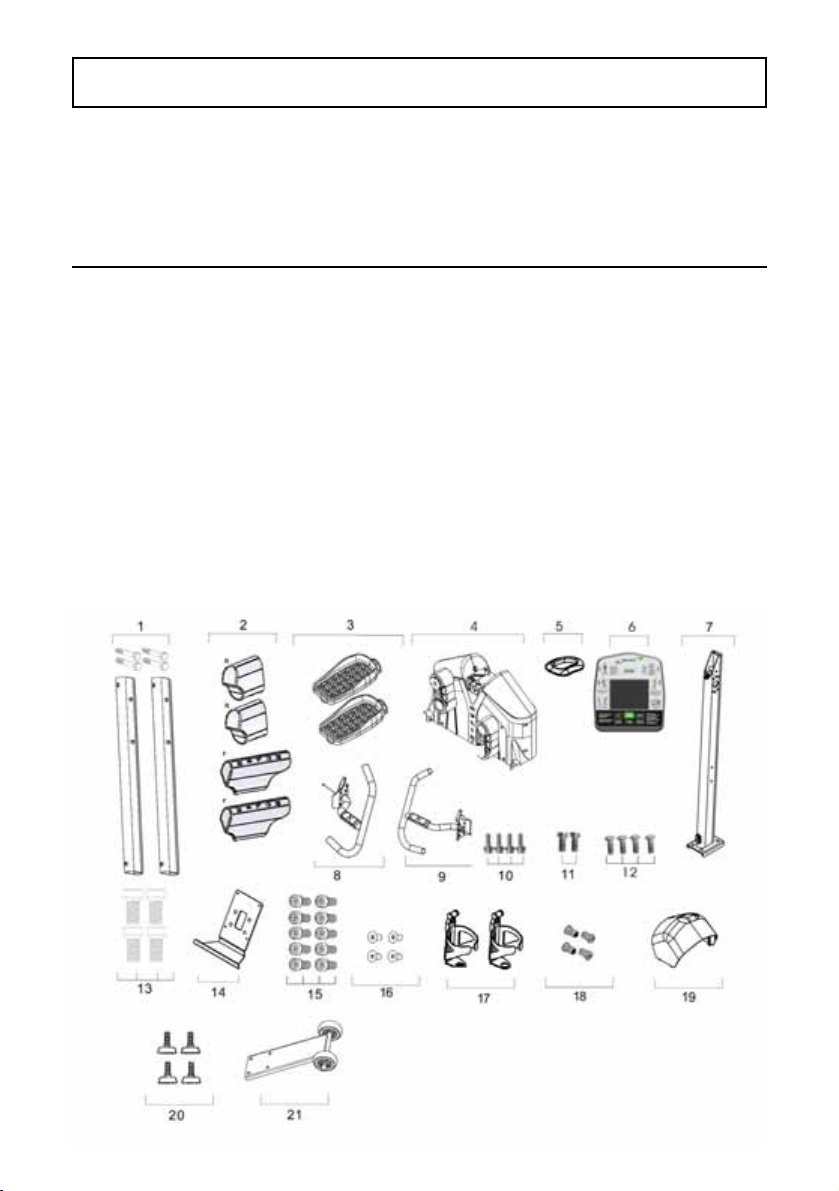
Item # Description Qty
1. Left and Right Stabilizer Legs 2
2. End Caps Front (F) Rear (R) 4
3. Pedal Assembly 2
4. Main Frame 1
5. Rubber Circle for Dome Cover 1
6. Computer 1
7. Center Upright Tube 1
8. Handlebar Right 1
9. Handlebar Left 1
10. Transport Plate Bolts 4
11. Pedal Frame Bolts* 2
Item #Description Qty
12. Computer Mounting Bolts 4
13. Allen Head Tapered Upright Bolts 4
14. Computer Mounting Plate 1
15. Handlebar Allen Head Bolts 10
16. Computer Mounting Bolts 4
17. Water Bottle Holder 1
18. Water Bottle Holder Bolts 2
19. Dome Cover 1
20. Stabilizer Leveling Feet 4
21. Transport Plate Assembly 1
2/ BEFORE YOU BEGIN
- 2 -
IMPORTANT: Read all instructions carefully. Assemble the Helix in accordance with
thestepsinthemanual.Layoutallpartsontheoorpriortoassemblytomakesure
you have all the parts listed below. In case of discrepancy, please contact Customer
PRE-ASSEMBLY CHECK LIST
*Note: Some parts may be factory pre-assembled.
( Item#11 - 6 bolts pre-installed in pedal)
A5-HLT3500.indd 4 27/02/2018 16:07

- 5 -
2/ STEP BY STEP PARTS
Parts Bags for ‘step by step’ assembly
The parts required for each step of the assembly process are sorted by step in
individual zip bags as shown below. Each step has required parts and each of
those parts is included with the bag printed with the assembly step.
It is recommended that these parts not be removed from the individual bags
until each step of the process to avoid mixing up or confusing parts.
Ifyoundthatyouaremissingpartsorthebagforastepismissing,please
contact Helix or your dealer to receive those items. You can refer to the parts
by the “step number” for ease of description.
STEP 3 Left and Right Frame
Legs Hex Head Bolts and
Washers - 4 of each
STEP 4 Pedal Frame Allen Head
Bolts - 2 Bolts. 6 additional
bolts pre-installed in pedal
frame.
STEP 5 Transport Plate Bolts
- 4 Bolts
STEP 6 Upright Post Allen Head
Tapered Bolts - 4 Bolts
STEP 7 Handlebar Allen Head Bolts
- 10 Bolts
STEP 8 Computer Bracket Philips
head Bolts - 4 Bolts
STEP 10 Computer Mounting Philips
Head Bolts – 4 Bolts
STEP 3 STEP 4 STEP 5 STEP 6
STEP 7 STEP 8 STEP 10
A5-HLT3500.indd 5 27/02/2018 16:07
- 6 -
3/ ASSEMBLY
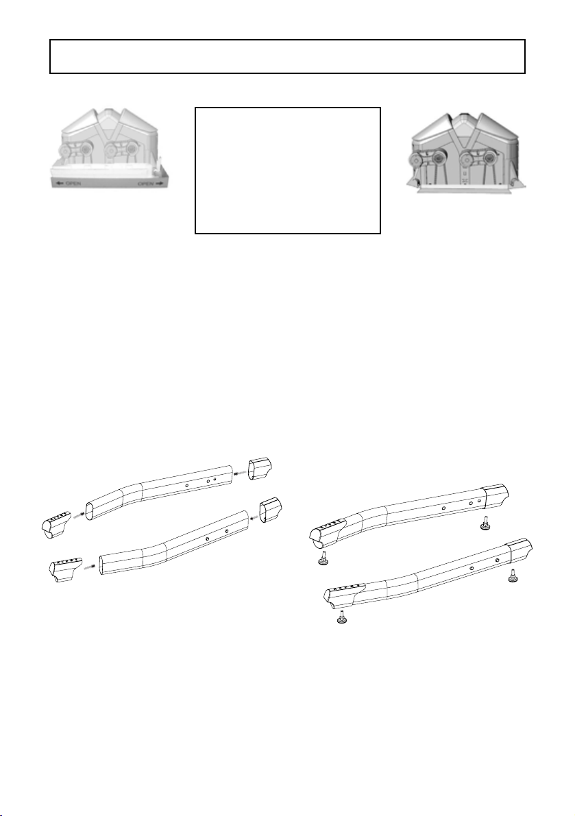
Step 1:
Puttheproductontheoorandremovethetopboxcovertorevealthe
Helix as show above. Where the box corners are printed “OPEN”, cut or tear
theboxandseparatethesecorners.Laythesidesattotheoor
Remove all parts from the box leaving just the main body of the
machine on the bottom of the box. remove all parts from their
plastic bags and organize on the oor beside the Helix.
Step 2:
Attach the End Caps (with HELIX branding ) to the left and right stabilizers.
The branded end caps install on the end farthest from the attaching bolt
holes. Attach Rear End caps (no branding) to the left and right stabilizers at
theendclosestotheattachingboltholes.Theyarefrontandrearspecic
butnotleftandrightspecic.Installthestabilizeradjustmentfeet(4)into
the bottom of the stabilizers and adjust as required.
IMPORTANT:
Do not remove the
Helix from the box
bottom until further
instructed later in
this assembly
manual.
A5-HLT3500.indd 6 27/02/2018 16:07
- 7 -
3/ ASSEMBLY
Step 3:
Insert the Stabilizer Leg assembly bolts
into the legs and secure as shown.
Tightentheseboltsrmly.
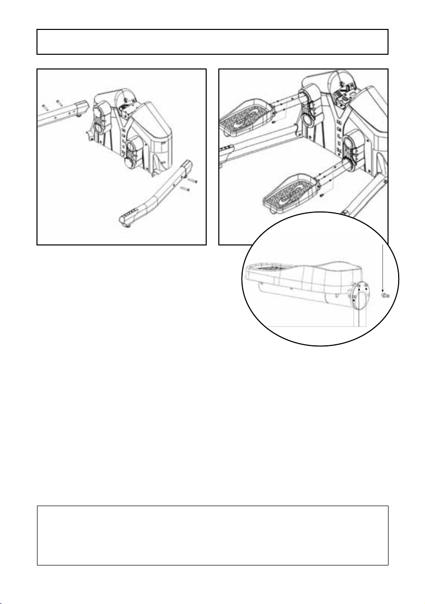
Step 4:
Align the bolt holes on the pedal frame with the bolts on the yoke of the
Crankarm.ThesetwopartsshouldttogethertoallowthePedalFrame
andyoketobecomeevenandushwitheachother.
Whileholdingtheframeinplace,rstinstallthetopboltspartiallytoallow
the pedal frame to “hang” on those bolts. Now partially install the bottom
left and bottom right bolts.
Slowly tighten all the bolts until the two parts become perfectly aligned to
eachotherwithnospacebetweentheparts.Thenrmlytightenallfour
bolts.
Repeat for the other Pedal Frame.
PLEASE NOTE THAT VISUAL INSPECTION IS REQUIRED TO
CONFIRM THAT THE PEDAL FRAME FLANGE AND THE CRANK YOKE
ARE ALIGNED AND FLUSH TO EACH OTHER.
Failuretoconrmthismayresultinboltfailure.
Step 3: Step 4:
3 bolts factory installed
Fourth bolt in
Step 4 Part Bag
A5-HLT3500.indd 7 27/02/2018 16:07

- 8 -
3/ ASSEMBLY
ASSEMBLY OF THE TRANSPORT PLATE
Step 5:
Find a box or step to place one stabilizer leg of the Helix onto in order to
raise one side off the ground. Install the transport plate with the 4 bolts as
shown.
A5-HLT3500.indd 8 27/02/2018 16:07

- 9 -
3/ ASSEMBLY
ASSEMBLY OF THE CENTER UPRIGHT TUBE
Step 6:
Place the upright post onto the main frame and install four (4) Tapered Allen
head bolts to tightly secure. After securing these bolts, connect the wire
from the frame to the wire from the upright tube.
Slide the Dome Cover down the post. The dome cover has two (2) tabs on
each side. Gently squeeze the cover together on each side near to the tabs
to allow the dome cover tabs to snap into the front and rear main housing.
Slide the Gasket ring down the post and secure into the dome cover.
A5-HLT3500.indd 9 27/02/2018 16:07

- 10 -
3/ ASSEMBLY
Step 7:
Install the Handlebars one side at a time. First insert the wire coming out
from the handlebar into the upright and feed wires through the opening in
the top of the upright post.
Insertve(5)Allenheadboltstoholdthehandleinplacebuthandtighten
only. Repeat process for the other handlebar. Again, only hand tighten the
bolts on each side.
Hole to feed hand
pulse wire one on each
side of upright
Main computer wire
A5-HLT3500.indd 10 27/02/2018 16:07

- 11 -
Step 8:
InstalltheComputermountingplatebyrstpullingthreesetsofwires
(Two (2) from the handle bars and one from the upright) through the hole
in the center of the plate.
Then making sure the wires are not pinched in between the plate and the
bracket, align the four holes in the plate with the four bolt holes (Two (2) on
each handlebar bracket) on the handle bar brackets and insert four phillips
head bolts and hand tighten only.
Now fully tighten the large Allen head bolts holding both the left and right
handlebars. Lastly, tighten the four Phillips head bolts holding the Computer
Mounting plate.
3/ ASSEMBLY
Feed 3 wires
carefully through
this hole
A5-HLT3500.indd 11 27/02/2018 16:07

- 12 -
Step 9:
Install Computer:
Connect the three wires coming out of the computer mounting plate with
the three wires coming out of the back of the computer. Simply snap the
connectors together. The two similar wires/connectors can be connected
with either of the same style on the back of the computer. It doesn’t matter
which goes to which.
Step 10:
Once the wires are all connected, carefully place the console bracket
ensuring that the wires are not pinched. Then install four console bolts
securely but do not over tighten.
3/ ASSEMBLY
Beware not to
pinch computer
wires
A5-HLT3500.indd 12 27/02/2018 16:07

- 13 -
Step 11:
Install Bottle Cages:
Takeonebottlecageandndtwo(2)bottlecagebolts.Alignthebottle
cage holes with the screw holes on either side of the upright. Install and
tighten two bottle cage bolts. Do not over tighten. Repeat the process for
the second water bottle.
3/ ASSEMBLY
A5-HLT3500.indd 13 27/02/2018 16:07
- 14 -
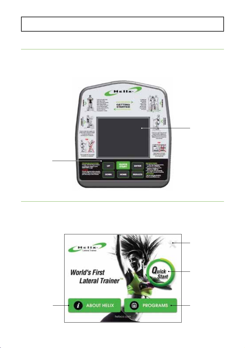
Layout
Please read the console operation instruction thoroughly and get familiar
with the console layout. Practice using this console before you start in order
to get a better understanding of the functions. Below is the console layout
and detailed operation instructions.
Displays
This console is equipped with institutive touch screen technology. Simply
touch the key on the screen to select the desired function. The screen
contents will vary according to the key touched.
Home page –
4/ COMPUTER
Functional
keys
Touch screen
Information
about Helix
Engineering
Setting Key
Quick Start
Key
Program Key
A5-HLT3500.indd 14 27/02/2018 16:07

- 15 -
5/ COMPUTER OPERATING INSTRUCTIONS
Program selection page – Touch any program key to select the program
and enter its program settings.
Program setting page – Enter the value for each area to complete the
settings. You may press “SAVE” key after inputting all the settings to save
your data for future use.
A5-HLT3500.indd 15 27/02/2018 16:07

- 16 -
Exercise page – The actual screen contents will vary depending on which
program is selected.
• Program prole window:
Displaysprogramproleduringprogramexecuting.Theprogram
prolewillbedifferentaccordingtowhichprogramisselected.Except
Heart Rate Control program, all other program proles will follow below
displaying rules.
There are 32 columns representing 32 segments of time; each
segment time = total program time divided by 32 columns. The height
of each column presenting the resistance level. There are 20 levels
to select from; the higher the graph, the higher resistance level is
selected. During exercising, a column will blink to indicate the time
segment you are currently in and show your workout progress.
• Data display windows:
There are 9 data display windows displaying “TIME, DISTANCE,
CALORIES, RPM, METS, WATT, LEVEL & PULSE” during exercising. For
heart rate control program, TARGET HR will be displayed as well.
• Pedal direction indicators: There are programs built with direction
change instructions to increase the intensity for these workout
routines. Please follow the message display to get the most out of
these programs.
5/ COMPUTER OPERATING INSTRUCTIONS
Data
Level
display &
adjusting
Data
Pedal
direction
Program
A5-HLT3500.indd 16 27/02/2018 16:07

- 17 -
5/ COMPUTER OPERATING INSTRUCTIONS - KEYS
Keys
There are two type of keys on this console for your continence, one set of
physical keys located on the bottom of the console and also touch screen
keys. The key functions exactly the same on both areas, therefore you can
use either one.
• Home key: Pressing this key anytime to get back to home page.
• Engineering Setting key: Pressing this key to enter engineering
setting page. This page is password protected. The default password
is “2015”. Enter this preset password to access the product record as
well as changing the units setting.
• About Helix key: Pressing this key to learn more about Helix.
• Quick Start & Start key: Pressing “Quick Start” key on home
page before you select a program will activate the Helix Interval
program immediately with default user values. Or pressing this key
(or “START” key on the screen) during the program setup will start the
selected program.
• Up/Down (/) keys: Used for user data adjusting during program
setup and resistance level/ heart rate adjustment while a program is
running.
• Enter key:Usedtoconrmprogramselectionanddataentry.
A5-HLT3500.indd 17 27/02/2018 16:07
- 18 -
• Programs key: Used to get into program selection page.
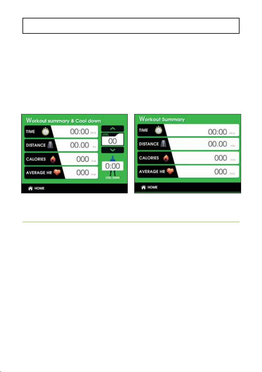
• Results key: Pressing this key while a program is running will enter
“Cool Down” mode. It is a 3 minutes cool down period. The resistance
level can be adjusted from 1 – 5 at this period.
When cool down time is reached or this key is pressed again will end the
program and workout summary will be displayed for your review. You can
always press and hold this key for 2 seconds to reset the console and return
to idle mode.
Basic Operation
• Power up: This product is powered by a generator and back up
battery. Please pedal to power up the console.
• Pause a program: If a program is running and there is no RPM for
3 seconds, the console will pause and stop accumulating data. The
pause time is 3 minutes. After that, the console will reset and screen
will be off and entering sleep mode. Within pause mode, pedal again to
resume the program.
• Start a program: To begin a workout program, press the “Quick
Start” key or “Programs” key to select a program. Then follow on
screeninstructiontosetupthepersonaldata.Whennishedentering
data, press the “Quick Start/Start” key to begin the workout. (You may
press “Quick Start/Start” key anytime during setup to bypass and start
the workout immediately.)
5/ COMPUTER OPERATING INSTRUCTIONS - BASIC OPERATION
A5-HLT3500.indd 18 27/02/2018 16:07

5/ COMPUTER OPERATING INSTRUCTIONS - WORKOUTS
• Default values: Initially the console is coded with a set of defaults for
express quick start. If you didn’t adjust these values before the
program started, they will be used for data calculations, such as
calories. It is recommended you adjust these values with your own
personal data to get the most accurate workout feedbacks. For your
convenience, if you press the “Save” key after the settings, the new
set of data will be stored as a new defaults. The factory initial defaults
are: age – 35; weight – 150lbs or 70kg; program time – 20 minutes
and target HR – 145bpm.
• End a program and review summary: Press “Results” key once
to end a program before the time is up and press it again to end the
cool down and review summary.
Workout Programs
There are three program categories for your selection: Classic programs;
Interval programs and HR control program.
Classic programs: This group includes Manual, Random, Simple intervals,
Valley, Rolling, Mountain, Olympian and Plateau programs.
Theseprogramsarepresetproleprogramsandbehavesimilar.Touch
thedesiredprogramkeyandpress“Enter”keytoconrm.Thenfollow
on screen instruction to set up the user data and start the program. You
may adjust the resistance level by pressing UP/DOWN (/) key during
program.Theprogramprolewillupdateaccordingly.
• MANUAL PROGRAM:
The default resistance level for
Manual program is L1.
• SIMPLE INTERVALS PROGRAM
PROFILE:
• ROLLING PROGRAM PROFILE:
• RANDOM PROGRAM:
This is a computer generated
proleprogramanditisdifferent
each time.
• VALLEY PROGRAM PROFILE:
• MOUNTAIN PROGRAM PROFILE:
A5-HLT3500.indd 19 27/02/2018 16:07

- 20 -
Interval programs: This group includes Helix intervals, Ramp intervals
and Pyramid intervals program.
These programs are designed to train your cardiovascular system strength
by allowing your body to alternate between high intensity-work periods and
low-intensity rest period. Research shows that interval training is the most
effectivetrainingfortnessandburnsmorecaloriesoverashortperiodof
time.
Besides intensity challenges, these programs are also equipped with
pedaling direction instruction to increase variety in your workout routine.
Follow the on screen instruction for the pedaling direction change.
Touchthedesiredprogramkeyandpress“Enter”keytoconrm.Then
follow on screen instruction to set up the user data and start the program.
For your safety, these programs are started with a Warm Up period of 3
minutes. During warm up, you may adjust the resistance level by pressing
Up/Down (/key from 1 - 5.
5/ COMPUTER OPERATING INSTRUCTIONS
• PLATEAU PROGRAM PROFILE:
Thisproleprogramalsoincludespedaldirectionchangeindications.
A5-HLT3500.indd 20 27/02/2018 16:07
Other manuals for HLT3500
1
Table of contents
Other HELIX Fitness Equipment manuals


Popular Fitness Equipment manuals by other brands


G-FITNESS
G-FITNESS AIR ROWER user manual

CAPITAL SPORTS
CAPITAL SPORTS Dominate Edition 10028796 manual

Martin System
Martin System TT4FK user guide

CIRCLE FITNESS
CIRCLE FITNESS E7 owner's manual

G-FITNESS
G-FITNESS TZ-6017 user manual

Accelerated Care Plus
Accelerated Care Plus OMNISTIM FX2 CYCLE/WALK user manual


