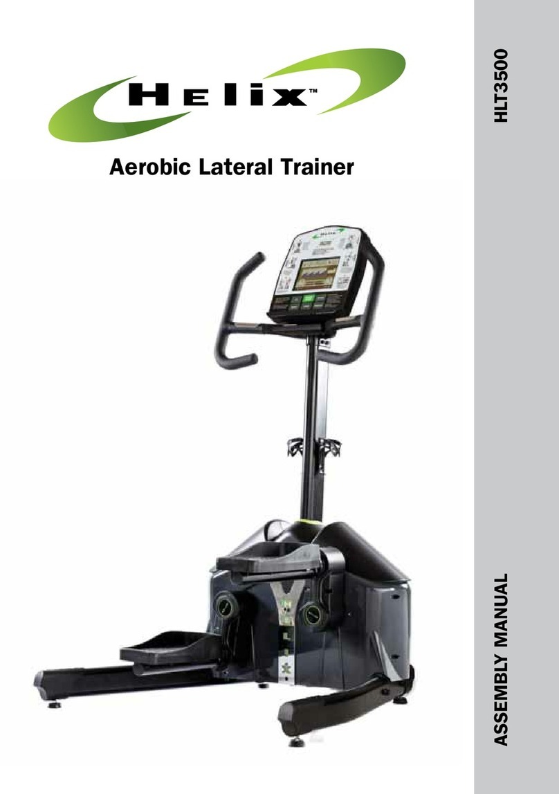
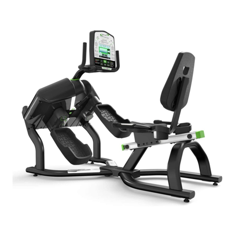
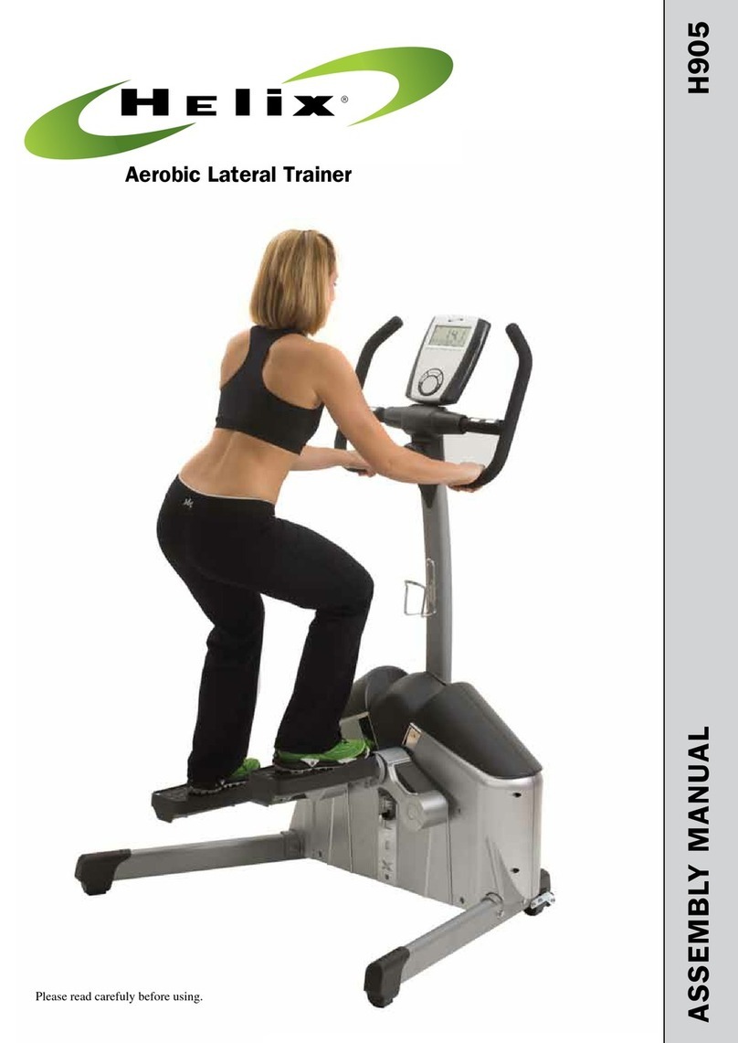
HELIX HLT2500 User manual

Aerobic Lateral Trainer
ASSEMBLY MANUAL HLT2500
HLT2500.indd 1 04/10/2015 19:09

- 3 -
1/ IMPORTANT SAFETY INFORMATION
IMPORTANT SAFETY PRECAUTIONS
1. Read the OWNER'S OPERATING MANUAL and all accompanying literature and follow it carefully
before using your machine.
2. Inspect your exercise machine prior to exercising to ensure that all nuts and bolts are fully tightened before
each use.
3. Most exercise equipment is not recommended for small children. Children should not use the machine
unless they are under adult supervision.
4. Exercise equipment has moving parts. In the interest of safety, keep others, especially children, at a safe
distance while exercising.
5. Warm up 5 to 10 minutes before each workout and cool down 5 to 10 minutes afterward. This allows your
heart rate to gradually increase and decrease and will help prevent straining muscles.
6. Never hold your breath while exercising. Breathing should remain at a normal rate in conjunction with the
level of exercise being performed.
7. Rest adequately between workouts. Muscles tone and develop during these rest periods. Beginners should
work out twice a week and increase gradually to 4 or 5 times per week.
8. Remove all jewelry, including rings, chains and pins before commencing exercise.
9. Always wear suitable clothing and footwear during exercise. Do not wear loose fitting clothing that could
become entangled with the moving parts of your exercise machine.
10. This machine is intended for household use only. It is not designed for commercial use.
IMPORTANT!!! THE MAXIMUM RECOMMENDED WEIGHT CAPACITY FOR YOUR Helix is
130Kg (286 lbs.) per user.
WARNING: Before commencing with any exercise program, please consult your family physician.
If at any time during exercise you feel faint, dizzy or experience pain, stop and consult your family
physician. In the event any of the above mentioned warnings are breached by the consumer, the
manufacturer may use same as a defense to any claim for injuries, damage or loss. The above warnings
are in no way intended to limit or modify the consumer's remedies for breach of warranties pursuant
to applicable Federal and State Laws of Regulations. They are being supplied strictly to ensure the
safety of the individuals using this product.
The Surgeon General
has determined that
lack of physical activity is
detrimental to your health.
!
THIS OWNER’S MANUAL CONTAINS ASSEMBLY, OPERATION, MAINTENANCE AND SAFETY
INFORMATION. IN THE INTEREST OF SAFETY, PLEASE MAKE CERTAIN THATYOU READ AND
UNDERSTAND ALL THE INFORMATION BELOW.
helix manuals_Helix H1000 - hires 24/04/2014 18:39 Page 3
IMPORTANT SAFETY INFORMATION
READ ALL INSTRUCTIONS BEFORE USING
THIS OWNER’S MANUAL CONTAINS ASSEMBLY, OPERATION, MAINTENANCE AND SAFETY INFORMATION. IN THE INTEREST OF
SAFETY, PLEASE MAKE CERTAIN THAT YOU READ AND UNDERSTAND ALL THE INFORMATION BELOW.
IMPORTANT SAFETY PRECAUTIONS
1. Read the OWNER’S OPERATING MANUAL and all accompanying literature and follow it carefully before using
your machine.
2. Inspect your exercise machine prior to exercising to ensure that all nuts and bolts are fully tightened before
each use.
3. Most exercise equipment is not recommended for small children. Children should not use the machine unless
they are under adult supervision.
4. Exercise equipment has moving parts. In the interest of safety, keep others, especially children, at a safe
distance while exercising.
5. Warm up 5 to 10 minutes before each workout and cool down 5 to 10 minutes afterward.
This allows your heart rate to gradually increase and decrease and will help prevent straining muscles.
6. Never hold your breath while exercising. Breathing should remain at a normal rate in conjunction with the
level of exercise being performed.
7. Rest adequately between workouts. Muscles tone and develop during these rest periods.
Beginners should work out twice a week and increase gradually to 4 or 5 times per week.
8. Remove all jewelry, including rings, chains and pins before commencing exercise.
9. Alwayswearsuitableclothingandfootwearduringexercise.Donotwearloosettingclothingthatcould
become entangled with the moving parts of your exercise machine.
IMPORTANT: THE MAXIMUM RECOMMENDED WEIGHT CAPACITY FOR YOUR Helix is 300lbs/ 136kg per user.
WARNING: Before commencing with any exercise program, please consult your family physician. If at any time during
exercise you feel faint, dizzy or experience pain, stop and consult your family physician. In the event any of the above
mentioned warnings are breached by the consumer, the manufacturer may use same as a defense to any claim for inju-
ries, damage or loss. The above warnings are in no way intended to limit or modify the consumer’s remedies for breach
of warranties pursuant to applicable Federal and State Laws of Regulations. They are being supplied strictly to ensure the
safety of the individuals using this product.
HLT2500.indd 2 04/10/2015 19:09

- 3 -
1/ IMPORTANT SAFETY INFORMATION
IMPORTANT SAFETY PRECAUTIONS
1. Read the OWNER'S OPERATING MANUAL and all accompanying literature and follow it carefully
before using your machine.
2. Inspect your exercise machine prior to exercising to ensure that all nuts and bolts are fully tightened before
each use.
3. Most exercise equipment is not recommended for small children. Children should not use the machine
unless they are under adult supervision.
4. Exercise equipment has moving parts. In the interest of safety, keep others, especially children, at a safe
distance while exercising.
5. Warm up 5 to 10 minutes before each workout and cool down 5 to 10 minutes afterward. This allows your
heart rate to gradually increase and decrease and will help prevent straining muscles.
6. Never hold your breath while exercising. Breathing should remain at a normal rate in conjunction with the
level of exercise being performed.
7. Rest adequately between workouts. Muscles tone and develop during these rest periods. Beginners should
work out twice a week and increase gradually to 4 or 5 times per week.
8. Remove all jewelry, including rings, chains and pins before commencing exercise.
9. Always wear suitable clothing and footwear during exercise. Do not wear loose fitting clothing that could
become entangled with the moving parts of your exercise machine.
10. This machine is intended for household use only. It is not designed for commercial use.
IMPORTANT!!! THE MAXIMUM RECOMMENDED WEIGHT CAPACITY FOR YOUR Helix is
130Kg (286 lbs.) per user.
WARNING: Before commencing with any exercise program, please consult your family physician.
If at any time during exercise you feel faint, dizzy or experience pain, stop and consult your family
physician. In the event any of the above mentioned warnings are breached by the consumer, the
manufacturer may use same as a defense to any claim for injuries, damage or loss. The above warnings
are in no way intended to limit or modify the consumer's remedies for breach of warranties pursuant
to applicable Federal and State Laws of Regulations. They are being supplied strictly to ensure the
safety of the individuals using this product.
The Surgeon General
has determined that
lack of physical activity is
detrimental to your health.
!
THIS OWNER’S MANUAL CONTAINS ASSEMBLY, OPERATION, MAINTENANCE AND SAFETY
INFORMATION. IN THE INTEREST OF SAFETY, PLEASE MAKE CERTAIN THATYOU READ AND
UNDERSTAND ALL THE INFORMATION BELOW.
helix manuals_Helix H1000 - hires 24/04/2014 18:39 Page 3
1 IMPORTANT SAFETY INFORMATION 2
Important Safety Precautions 2
Weight Limit Capacities 2
Warning 2
2 BEFORE YOU BEGIN 3-6
Parts Bags for ‘step by step’ assembly 3
Exploded drawing 4
Pre-Assembly Check List 5
Unpacking Information 6
3 ASSEMBLY 7-11
4 COMPUTER 12
Computer Instructions 12-18
Computer Button Functions 18
5 CUSTOMER INFORMATION
Customer Service back cover
The parts required for each step of the
assembly process are sorted by step
in individual zip bags as shown left.
Each step has required parts and each
of those parts is included with the bag
printed with the assembly step.
It is recommended that these parts not
be removed from the individual bags
until each step of the process to avoid
mixing up or confusing parts.
Ifyoundthatyouaremissingpartsor
the bag for a step is missing, please
contact Helix or your dealer to receive
those items. You can refer to the parts
by the “step number” for ease of
description.
2 PARTS BAGS FOR ‘STEP BY STEP’ ASSEMBLY
2 TABLE OF CONTENTS PAGE 3
HLT2500.indd 3 04/10/2015 19:09

Item# Part Description Qty
1 Left and Right Frame Legs 2
2 Transport Wheel Assembly 1
3 Pedal Frames and Covers 2
4 Main Frame 1
5 Rubber Gasket for Upright 1
6 Electronic Console Display 1
7 Center Upright Post 1
8 Handlebars Left and Right 2
9 Console Mounting Plate 1
10 Water Bottle Holder Bolts 2
11 Pedal Frame Bolts 6
12 Computer Console Mounting Bolts 4
13 Center Upright Mounting Bolts 4
14 Handlebar Bolts 8
15 Stabilizer Bolts 4
16 Tool (N/A)
17 Water Bottle Holder 1
18 Console Mounting Plate Bolts 4
19 Transport Wheel Assembly Bolts(1-long 1-short) 2
20 Dome Shaped Cover 1
21 Front / Rear End Cap 4
22 Adjustable feet
These 2 bolts are
pre-installed
May be factory
pre-installed
HLT2500.indd 4 04/10/2015 19:09

2 BEFORE YOU BEGIN PAGE 5
IMPORTANT: Read all instructions carefully. Assemble the Helix in accordance with the steps in
the manual. All tools required for assembly are included with your Helix. Lay out all parts on the
oor.Makesurethatyouhaveallthepartslistedbelowbeforebeginningassembly.Incaseofa
discrepancy, please contact our Customer Service Department at the email address or customer
service number listed on the back page of this Owner’s Manual.
ITEM DESCRIPTION QTY
#
1 LEFT AND RIGHT FRAME LEGS 2
2 TRANSPORT WHEEL ASSEMBLY (May be factory pre-assembled) 2
3 PEDAL FRAMES AND COVERS 2
4 MAIN FRAME 1
5 RUBBER GASKET FOR UPRIGHT 1
6 ELECTRONIC CONSOLE DISPLAY 1
7. CENTER UPRIGHT POST 1
8. HANDLEBARS LEFT AND RIGHT 2
9. CONSOLE MOUNTING PLATE 1
10. WATER BOTTLE HOLDER BOLTS 2
11. PEDAL FRAME BOLTS 6
ITEM DESCRIPTION QTY
#
12. COMPUTER CONSOLE MOUNTING BOLTS 4
13. CENTER UPRIGHT MOUNTING BOLTS 4
14. HANDLEBAR BOLTS 8
15. LEFT & RIGHT STABILIZER BOLTS 4
16. ASSEMBLY TOOLS 5
17. WATER BOTTLE HOLDER 1
18. CONSOLE MOUNTING PLATE BOLTS 4
19. TRANSPORT WHEEL ASSEMBLY BOLTS
(1-LONG 1-SHORT) (May be factory pre-assembled) 2
20. DOME SHAPED COVER 1
21. FRONT / REAR END CAP 4
22. ADJUSTABLE FEET 4
PRE-ASSEMBLY CHECK LIST
HLT2500.indd 5 04/10/2015 19:09

1
3 UNPACKING / ASSEMBLY PAGE 6
IMPORTANT:
Do not remove the Helix from the box bottom until
further instructed later in this assembly manual.
Step 1:
PuttheproductontheoorandremovethetopboxcovertorevealtheHelixasshowabove.Wherethe
boxcornersareprinted“OPEN”,cutorteartheboxandseparatethesecorners.Laythesidesattothe
oor.
Step 2:
Remove all parts from the box leaving just the main body of the machine on the bottom of
the box. Remove all parts from their plastic bags and organize the oor beside the Helix.
STABILIZERS INSTALLATION :
Step 3:
Attach the End Caps (with HELIX branding ) to the left and right stabilizers. The branded end caps install
on the end farthest from the attaching bolt holes. Attach Rear End caps (no branding) to the left and
rightstabilizersattheendclosestotheattachingboltholes.Theyarefrontandrearspecicbutnotleft
andrightspecic.
Install the stabilizer adjustment feet (4) into the bottom of the stabilizers and adjust as required
Figure #2.
2
HLT2500.indd 6 04/10/2015 19:09

If the Helix is not stable on
theoor,thelevelcanbe
adjusted with any of the
leveling feet at each corner
of the Helix
3 ASSEMBLY - STABILIZERS PAGE 7
3
Step 4:
Insert the Stabilizer Leg assembly bolts
into the legs and secure as shown Figure
#3.
Tightentheseboltsrmly.
HLT2500.indd 7 04/10/2015 19:09

3 ASSEMBLY / PEDALS PAGE 8
Step 4:
The pedals have two bolts pre-installed
and require two Hex head bolts from the
Step 4 hardware pack.
Holding the frame up to the crank arm,
loosely install the lower left and lower
right hex head bolts through the round
pedalangeintotheidenticalangeon
the crank assembly.
This will allow the pedal to hang on the
crank assembly.
Then thread the top two pre-installed bolts
into the crank assembly round plate.
Continue threading all 4 bolts into the
crankassemblyangeuntiltheyareall
snugandtheangesareushtogether.
Nowtightenall4boltsveryrmly.
Repeat for the other pedal assembly.
It is critical that a full visual inspection be completed to ensure
that the pedal frame round ange and the crank assembly round
ange are ush together and that all four bolts are completely
and rmly installed.
Failuretoensurethatthetwoangesarermlyincontactwillresultin
failure of the pedal frame bolts.
2 bolts are
pre-installed
HLT2500.indd 8 04/10/2015 19:09

3 ASSEMBLY - CENTER UPRIGHT TUBE PAGE 9
Step 5:
Placethecenteruprightonthemainbody.InstallthetwofrontAllenboltsrstbutdonotfullytighten
Figure #1. Then install the two rear Allen bolts. After both are installed, make sure upright is level and
ushwiththebaseandfullytightenall4Allenbolts.
Step 7:
Slidethecoverdowntothebottomofthecenteruprighttubeandtthetabsintotheholesinthelower
plastichousingtotsnugglyinplaceasshownFigure #4.
Applyonlygentlepressuretotthetabsandthecoverinplace.Slidetherubbercircledownthecenter
upright tube and push into place as shown.
Step 6:
At the base of the main upright connect the wiring harness coming from the upright to the wiring
harness coming from the main body of the Helix Figure #3. After these are connected, tuck the wire
and connection into the upright and be sure the wire is clear of the large gears in the body.
1 2
3 4
HLT2500.indd 9 04/10/2015 19:09

3 ASSEMBLY - HANDLE BARS PAGE 10
HANDLE BARS INSTALLATION :
Step 8:
Foreaseofinstallation,rstinstalltwohandlebarboltstemporarilyoneineachoftheholesshowabove
the arrow in Figure #1 above.
Step 9:
Then holding one handlebar in your hand, carefully feed the pulse sensor wire into the upright and out
of the hole at the top of the upright Figure #3. Once the wire is out of the top of the upright, remove
one of the temporary bolts and use it to secure the handlebar in place while you prepare to install the
remaining 3 bolts into the handlebar on that side. Repeat for the other side as shown above Figure #4.
1 2
3 4
HLT2500.indd 10 04/10/2015 19:09

3 ASSEMBLY - CONSOLE / COMPUTER PAGE 11
Step 10:
Console Bracket Installation: Feed three (3) wires through the center hole of the console bracket as
shown in Figure #1 above. Once the three wires are completely through, install the four (4) bolts
securing the console bracket to the upright (Figure #2).
COMPUTER INSTALLATION
1 2
Slide onto bracket.
Beware not to pinch
the computer wires
Step 12:
Once the wires are all connected, slowly slide the computer onto the mounting plate (Figure #2).
Please be extremely careful not to pinch the wires as the computer slides down onto the bracket. Once
fully slid onto the bracket, install the four computer mounting bolts in the four holes on the back of the
computer (Figure #3).
Do not over tighten. Just make them secure.
Step 11:
Connect the three wires coming out of the computer
mounting plate with the three wires coming out of
the back of the computer. Simply snap the connec-
tors together. The two similar wires/connectors can
be connected with either of the same style on the
back of the computer. It doesn’t matter which goes
to which (Figure #1)
1
2
3
#12 #12
HLT2500.indd 11 04/10/2015 19:09

3 ASSEMBLY - WHEELS / WATER BOTTLE PAGE 12
1 2 3 4
Step 11:
Find the two bolt holes in the Center Upright Post. Locate the ‘Step 14’ hardware bag that contains the
water bottle bolts (Figure #1)
(Figure #2) Hold the water bottle holder up to the post as shown and install a bolt in the lower hole in
the water bottle holder bracket (Figure #3) and through to the lower bolt hole on the upright.
Do not tighten at this time.
Tilt the water bottle holder upright to align the top hole in the bracket with the top hole on the center
upright post. Install a 2nd bolt into that hole and then tighten with the allen key as shown in Figure
#4.
Step 13: NOTE: This part may be factory pre-installed
Raise up one side of the Helix onto a box or one of the styrofoam blocks from the packaging. Install
the transport wheel as shown. Make note in (Figure #1) above the location of the longer bolt and the
shorter bolt.
1 2
WATER BOTTLE HOLDER INSTALLATION
HLT2500.indd 12 04/10/2015 19:09

Modes:
Training Mode: When the user steps onto the Helix, the computer will be automatically powered
on. A long beep will sound, and then the computer will enter into its initial screen awaiting input.
The display will scroll from Figure-1, to Figure-2 above)
Stand-by Mode: When the Helix is not in use for three (3) minutes, it will automatically enter
into the Sleep. There will be no computer display in that mode.
Display:
The computer on the Helix has two display screens. One is the Data Display and the other the Dot
Matrix Display. The Data display windows can display the following information:
Time-Level-RPM-Watts
Calories-Distance-Pulse-Mets
These two sequences can be toggled between by pressing the SCAN key or set to automatically
scan by holding the Scan button for three (3) seconds to automatically scan between the two
displays.
Figure 1 Figure 2
4 COMPUTER PAGE 13
HLT2500.indd 13 04/10/2015 19:09

Dot matrix display:
ThedotmatrixwillbeusedtodisplaytheProgramprole
for the active program.
The table will change its pattern based upon the Program
chosen by the user. Columns represent the progression
oftimeasthedotmatrixscreenllsfromlefttoright.
Rows indicate the resistance level by the number of
LEDs that are lit vertically. See table to right referring to
the Levels indicated.
Program Keys:
To the left and right of the large Dot Matrix display are
eight Program Keys.
These program keys can be used to directly choose a
program. Alternatively, the user can scroll the programs
with the up or down key.
WhentheHelixcomputerrststarts,thisscrollingmessagewillreadacrosstheDataDisplay
Screen. “CHOOSE PROGRAM OR QUICK START”
Pressing the QUICK START key in the center of the console, will begin the workout immediately
with a default time of 20 minutes and Level 1 of Manual mode.
4 COMPUTER OPERATING INSTRUCTIONS PAGE 14
HLT2500.indd 14 04/10/2015 19:09

Quick Start: Program Selection:
Whenthecomputerrststarts,theusercanchooseoneofeightprogrambuttonsoneitherside
of the large dot matrix display; Manual, Random, Interval, Heart Rate Control, Valley, Rolling,
Mountain or Olympian. Choose the program by pushing the button beside the program name or
by scrolling through the choices with the up or down key.
When the program shown is the program desired, press the Enter key. The computer will then
request the user’s weights to be entered. The message will read “SET WEIGHT 150LB”. Using the
up or down key, adjust to the user’s weight. When the screen displays the correct weight, press
the ENTER key.
The computer will then request the workout. The message will read “SET TIME 0:00” Using the up
or down key, set the desired workout time. Once the computer displays the desired time, press
the ENTER key.
The computer will next request the exercise resistance level. The message will read “SET LEVEL
1”. Using the up key, set the desired level of resistance. Once the desired level is displayed, press
the ENTER key. At any time during the workout, the Resistance level can be adjusted up or down
using the up or down keys.
4 COMPUTER OPERATING INSTRUCTIONS PAGE 15
HLT2500.indd 15 04/10/2015 19:09

Heart Rate Control Program
If the user chooses the Heart Rate Control program, the user will again be asked to enter their
weight as above. The user will then be asked to set the desired heart rate. The message will read
“SET HRC 80”. Using the up and down keys, set the desired heart rate. When the desired heart
rate is displayed, press the ENTER key. The user will then be asked to set the workout time as
above.
Pre-dened program prole:
MANUAL PROGRAM RANDOM PROGRAM
INTERVAL PROGRAM H.R.C PROGRAM
VALLEY PROGRAM ROLLING PROGRAM
MOUNTAIN PROGRAM OLYMPIAN PROGRAM
4 COMPUTER OPERATING INSTRUCTIONS PAGE 16
HLT2500.indd 16 04/10/2015 19:09

Cool Down:
At any time during the workout, press the CLEAR key to proceed directly into the Cool Down
mode. Also, at the end of the workout time, the computer will automatically proceed into the Cool
Down Mode. The message will display “COOL DOWN”, and will display for 5 seconds. Press the
up or down key if you wish to adjust the LEVEL, during the Cool Down period. The Cool Down
period will depend on the total duration of exercise.
Results Mode Total Time Total Distance
Total Calories Average Pulse Average Watts
Average RPM Summary Mode:
During Cool Down mode, press the CLEAR key to
proceed into Summary Mode or when the set Program
time is over the computer will automatically proceed to
Summary Mode. The computer will display “SUMMARY
MODE” for 5 seconds and then cycle through the
following data: Total Time, Distance, Calories, Average
Pulse, Average Watts and Average RPM.
4 COMPUTER OPERATING INSTRUCTIONS PAGE 17
HLT2500.indd 17 04/10/2015 19:09

Heart Rate Display
Heart rate will be display by either holding both hands on the hand grip sensors or by wearing
a Polar compatible Heart rate chest strap (not included). When holding the hand grip sensors or
whenwearingthecheststrap,thedotwillashinthePULSEeld.If“P”isshowinginthePulse
eld,pleaseeitheradjustyourgriporadjustthePolarCheststraptoimprovetheconnection.
Please continue to hold the hand grips for a minimum of 20 seconds.
Control Keys:
ENTERkey-Toconrmentriesandproceedtonextentry.
QUICKSTART key - Once the computer powers
on, this button will pre-set the workout to start
at Level 1 Manual mode and 20 minute period.
SCAN key - During workout, press this key
to change display window between the upper
indicators or lower indicators. Hold this key for
three seconds to scan back and forth between the upper and lower display.
Upper Lower
During the “Result mode” pressing the SCAN key will cycle shows the following data:
Total Time →Total Distance →Total Calories →Average RPM →Average PULSE →Average Watts
CLEAR key – At any time during set up, this key will return you back to the previous setting to
make a change to that setting. During the workout, pressing this key will put the program into
the Cool Down mode. Pressing this key once in Cool Down will put the program into Results Mode.
While in Result Mode, pressing this key will reset the computer completely.
UP key - Used to select workout Program, adjust Weight, adjust Time, adjust Heart Rate Control
value and adjust resistance level during setup. Using this key, the resistance level can be changed
during a workout.
DOWN Key – Used to select workout Program, adjust Weight, adjust Time, adjust Heart Rate
Control value and to adjust resistance level during setup. Using this key,
the resistance level can be changed during a workout.
4 COMPUTER OPERATING INSTRUCTIONS PAGE 18
HLT2500.indd 18 04/10/2015 19:09

Functions
Windows Display Range Windows Display Range
TIME 0:00 - 99:00 RPM 0 - 255 rpm
DISTANCE 0.00 - 99.99 METS 0.0 – 99.9
PULSE 50 - 210 bpm WEIGHT(ENGLISH) 30-400 (lb.)
WEIGHT(METRIC) 15-250 (kg)
CALORIES 0 - 999 kcal RESISTANCE LEVEL L1 – L16
WATT 0 - 999 watt
4 COMPUTER OPERATING INSTRUCTIONS PAGE 19
PROGRAM KEYS
There are eight (8) program keys on the left and right side of the Large Dot Matrix display. These
program keys can be used directly to choose a program instead of scrolling up and down through
the program list. The following keys are available:
Manual, Random, Interval, ♥ Control (Heart Rate Control), Valley, Rolling, Mountain and Ironman
HLT2500.indd 19 04/10/2015 19:09

Forcustomerservice,werstrecommendyoucontactthedealerwhereyoupurchasedtheHelix.
They will be able to resolve any issues the fastest.
If you cannot reach the dealer, please feel free to contact Helixco at
Distributed under license from Kriptonite Corp by Helix Company, a division of M & S Distribution, Inc, 572 Freeport Street, Unit A,
Boston, MA 02122
This product is patented in the US and other International Patents and patents pending.
US Patent Number 7,108,638
Helix® is a registered trademark of M & S Distribution, Inc. All rights reserved.
HLT2500.indd 20 04/10/2015 19:09
Other manuals for HLT2500
1
Table of contents
Other HELIX Fitness Equipment manuals
Popular Fitness Equipment manuals by other brands
Trojan
Trojan VIBROSTATION Care instructions and assembly manual
Domyos
Domyos BM 490 operating instructions

MOB
MOB MO6199 user manual
Domyos
Domyos HG 90 BOXE operating instructions
laerdal
laerdal HeartStart M5086A Directions for use
Precor
Precor Commercial Adaptive Motion Trainer C100i User's reference manual
