HELIX H 1000 ESPRIT User manual
ASSEMBLY MANUAL H1000
Please read carefuly before using.
Aerobic Lateral Trainer
helix manuals_Helix H1000 - lowres 26/06/2013 13:11 Page 1

helix manuals_Helix H1000 - lowres 26/06/2013 13:11 Page 2

- 3 -
1/ IMPORTANT SAFETY INFORMATION
IMPORTANT SAFETY PRECAUTIONS
1. Read the OWNER'S OPERATING MANUAL and all accompanying literature and follow it carefully
before using your machine.
2. Inspect your exercise machine prior to exercising to ensure that all nuts and bolts are fully tightened before
each use.
3. Most exercise equipment is not recommended for small children. Children should not use the machine
unless they are under adult supervision.
4. Exercise equipment has moving parts. In the interest of safety, keep others, especially children, at a safe
distance while exercising.
5. Warm up 5 to 10 minutes before each workout and cool down 5 to 10 minutes afterward. This allows your
heart rate to gradually increase and decrease and will help prevent straining muscles.
6. Never hold your breath while exercising. Breathing should remain at a normal rate in conjunction with the
level of exercise being performed.
7. Rest adequately between workouts. Muscles tone and develop during these rest periods. Beginners should
work out twice a week and increase gradually to 4 or 5 times per week.
8. Remove all jewelry, including rings, chains and pins before commencing exercise.
9. Always wear suitable clothing and footwear during exercise. Do not wear loose fitting clothing that could
become entangled with the moving parts of your exercise machine.
10. This machine is intended for household use only. It is not designed for commercial use.
IMPORTANT!!! THE MAXIMUM RECOMMENDED WEIGHT CAPACITY FOR YOUR Helix is
130Kg (286 lbs.) per user.
WARNING: Before commencing with any exercise program, please consult your family physician.
If at any time during exercise you feel faint, dizzy or experience pain, stop and consult your family
physician. In the event any of the above mentioned warnings are breached by the consumer, the
manufacturer may use same as a defense to any claim for injuries, damage or loss. The above warnings
are in no way intended to limit or modify the consumer's remedies for breach of warranties pursuant
to applicable Federal and State Laws of Regulations. They are being supplied strictly to ensure the
safety of the individuals using this product.
The Surgeon General
has determined that
lack of physical activity is
detrimental to your health.
!
THIS OWNER’S MANUAL CONTAINS ASSEMBLY, OPERATION, MAINTENANCE AND SAFETY
INFORMATION. IN THE INTEREST OF SAFETY, PLEASE MAKE CERTAIN THAT YOU READ AND
UNDERSTAND ALL THE INFORMATION BELOW.
helix manuals_Helix H1000 - lowres 26/06/2013 13:11 Page 3

helix manuals_Helix H1000 - lowres 26/06/2013 13:11 Page 4

- 5 -
The parts required for each step of the assembly
process are sorted by step in individual zip bags
as shown left. Each step has required parts and
each of those parts is included with the bag
printed with the assembly step.
It is recommended that these parts not be
removed from the individual bags until each step
of the process to avoid mixing up or confusing
parts.
If you find that you are missing parts or the bag
for a step is missing, please contact Helix or
your dealer to receive those items. You can refer
to the parts by the “step number” for ease of
description.
TABLE OF CONTENTS
1 IMPORTANT SAFETY INFORMATION 3
Important Safety Precautions 3
Weight Limit Capacities 3
Warning 3
2 BEFORE YOU BEGIN 5-8
Parts Bags for ‘step by step’ assembly 5
Exploded drawing 6
Pre-Assembly Check List 7
Unpacking Information 8
3 ASSEMBLY 8-13
4 GETTING STARTED 14
Computer Instructions 14-16
Computer Button Functions 17-18
5 CUSTOMER INFORMATION
Customer Service back cover
READ ALL INSTRUCTIONS BEFORE USING
2/ PARTS BAGS FOR ‘STEP BY STEP’ ASSEMBLY
helix manuals_Helix H1000 - lowres 26/06/2013 13:11 Page 5
- 6 -
helix manuals_Helix H1000 - lowres 26/06/2013 13:11 Page 6

- 7 -
2/ BEFORE YOUR BEGIN
IMPORTANT: Read all instructions carefully. Assemble the Helix in accordance with the steps in the manual. All
tools required for assembly are included with your Helix. Lay out all parts on the floor. Make sure that you have all
the parts listed below before beginning assembly. In case of a discrepancy, please contact our Customer Service
Department at the email address or customer service number listed on the back page of this Owner’s Manual.
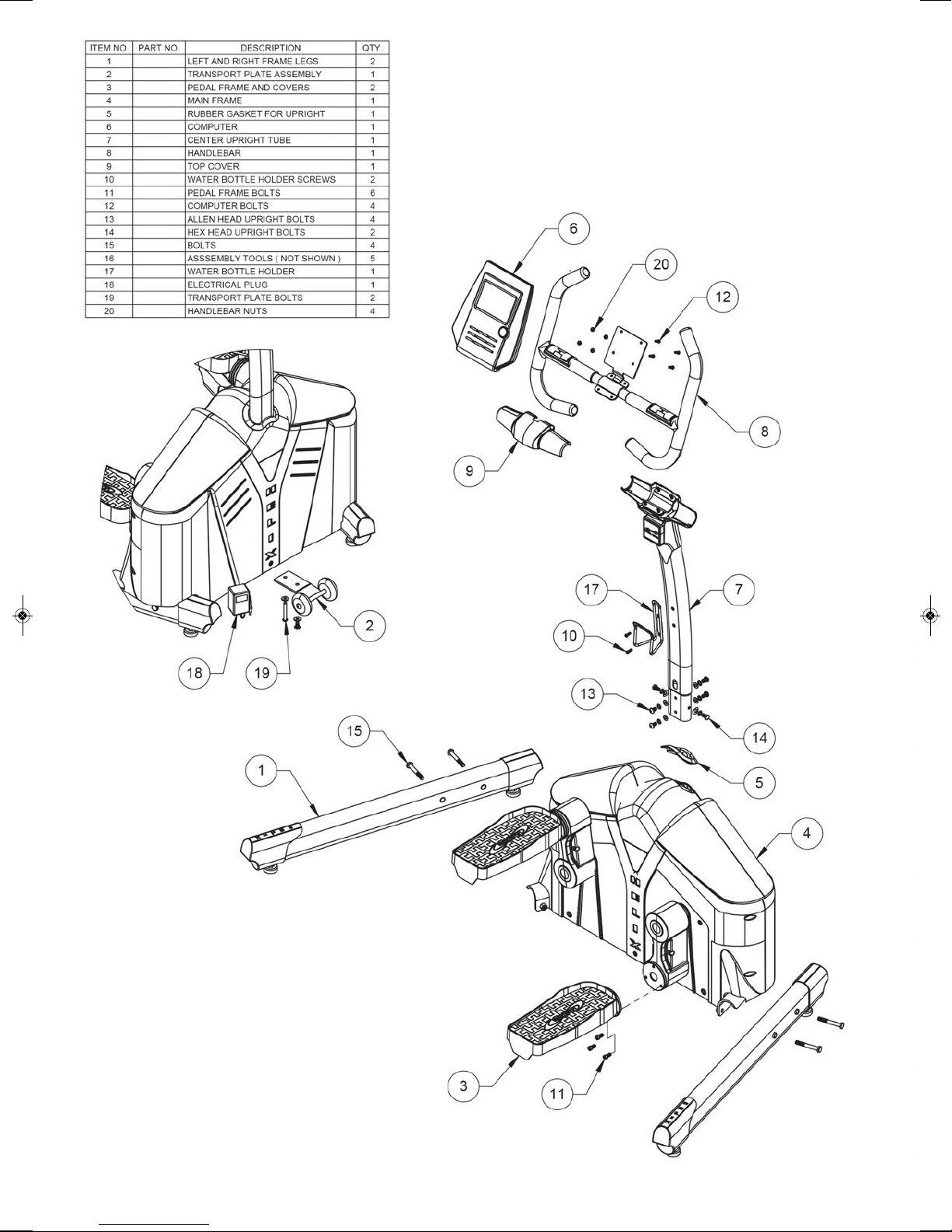
PRE-ASSEMBLY CHECK LIST
Note:
Some parts may be factory pre-assembled.
Item # Description Qty
1 LEFT AND RIGHT FRAME LEGS 2
2 TRANSPORT PLATE ASSEMBLY 2
3 PEDAL FRAME AND COVERS 2
4 MAIN FRAME 1
5 RUBBER GASKET FOR UPRIGHT 1
6 COMPUTER 1
7. CENTER UPRIGHT TUBE 1
8. HANDLEBAR 1
9. TOP COVER 1
10. WATER BOTTLE HOLDER SCREWS 2
Item #Description Qty
11. PEDAL FRAME BOLTS 6
12. COMPUTER BOLTS 4
13. ALLEN HEAD UPRIGHT BOLTS 4
14. HEX HEAD UPRIGHT BOLTS 2
15. BOLTS 4
16. ASSEMBLY TOOLS 5
17. WATER BOTTLE HOLDER 1
18. ELECTRICAL PLUG 1
19. TRANSPORT PLATE BOLTS 2
20. HANDLEBAR NUTS 4
helix manuals_Helix H1000 - lowres 26/06/2013 13:11 Page 7

- 8 -
3/ UNPACKING / ASSEMBLY
STEP 1:
Put the product on the floor and remove the top box cover to reveal the Helix as show above. Where the box
corners are printed “OPEN”, cut or tear the box and separate these corners. Lay the sides flat to the floor.
STEP 2:
Remove all parts from the box leaving just the main body of the machine on the bottom of the box.
remove all parts from their plastic bags and organize the floor beside the Helix.
STEP 3:
Each Left and Right Frame Legs are marked “L” and “R” with a sticker. While facing the Helix, place the left
leg on the left side of the machine and the right leg on the right side of the machine.
Insert the Frame Leg assembly bolts into the lefts and secure using the “T” wrench as shown. Tighten these
bolts firmly.
IMPORTANT:
Do not remove the
Helix from the box
bottom until further
instructed later in
this assembly
manual.
1
2
If the Helix is not stable on the
floor, the level can be adjusted
with any of the leveling feet at
each corner of the Helix
3
helix manuals_Helix H1000 - lowres 26/06/2013 13:11 Page 8
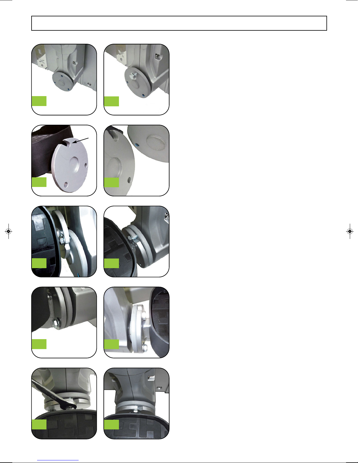
3/ ASSEMBLY - PEDALS
STEP 4:
Using the 6 Hex head bolts and washers from STEP 4
Plastic Parts Bag, install one bolt and one washer in the
top bolt of the plate as shown in Figure #5.
On the Pedal assembly make note of the slot in the
round disk as shown in Figure #6.
This slot is used to slide onto the bolt that you installed
in the round disk on the crank arm. Slide the slot over
the bolt as shown in Figure #8 . Be sure that the washer
is on the side of the bolt head and not between the two
connecting parts.
Turn the Pedal Assembly to align the two round plates
as shown in Figure #9
Next install a hex head bolt and washer on the right side
of the disk as shown in Figure #10. Repeat this again on
the other side of the disk as shown in Figure #11. There
will be a total of three bolts installed.
Note that one round disk has a protrusion and one has
an indentation as shown in Figure #7. These should fit
together evenly when assembled. Do not fully tighten
the hex head bolts until you are sure these two parts are
aligned. Then fully tighten the bolts with a Wrench as
shown in Figure #12.
Repeat the process for the 2nd pedal assembly.
45
67
89
10 11
12 13
- 9 -
Slot
helix manuals_Helix H1000 - lowres 26/06/2013 13:11 Page 9

- 10 -
3/ ASSEMBLY - CENTER UPRIGHT TUBE
STEP 6:
Slide the upright tube into the frame as shown in Figure #4 & Figure #5 above. When fully installed first install
the two Hex Head bolts (Step 6 Plastic bag ) on either side of the upright as shown in Figure #6 & Figure #7
Do not fully tighten these bolts at this time.
STEP 7:
Take 4 Allen Head Bolts ( Step 7 Plastic Bag) and install these four bolts as shown in Figure #8 and Figure #9
Now fully tighten all 6 of these bolts.
34
12
Removeable
Cover
8
67
5
9
Allen Head Bolts
Front and back
Hex Head Bolts
Left and right of post
Remove the Center Dome Cover by
pressing in at the bottom on both
sides and lifting off of the Helix. (See
Figure #1) above.
Holding the Center Upright Tube as
shown in Figure #2, first slide on the
Rubber Circle for Upright. The side
of the Rubber Circle that has a minor
indentation should be positioned
toward the back of the Center
Upright Tube.
The back can be determined by the
opposite side of the Tension
Adjustment Knob. After sliding on
the Rubber Circle, then slide on the
‘Removeable Cover’ The cover
should be installed with the hole
toward the back side of the Upright
so that the majority of the cover sits
on the front of the Center Upright
Tube. (See Figure #2)
Slide the cover up as shown in
Figure #3 and pull the elastic band
around the tension knob to hold the
cover in place.This allows the cover
to be out of the way for the bolt
assembly of the Center Upright Tube
STEP 5:
helix manuals_Helix H1000 - lowres 26/06/2013 13:11 Page 10
- 11 -
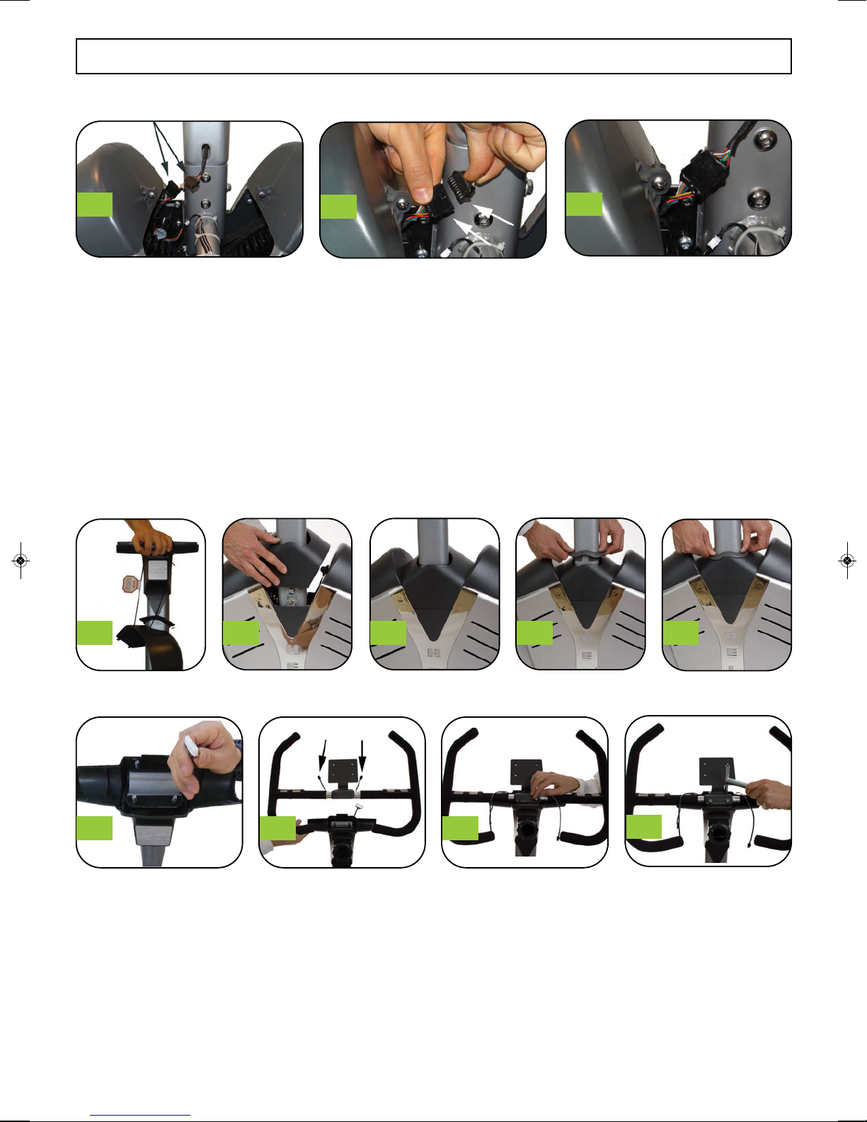
3/ ASSEMBLY - CABLES - COVER AND HANDLE BARS
STEP 8:
At the bottom of the upright there are two cables that connect to each other with the black connectors at the end. The
black connectors only connect in one direction. Gently try to connect the male and female connectors and if not easy
to connect, flip over one connector and try again. The connectors should snap easily together with a click sound.
STEP 10:
Remove elastic cord from around the tension adjuster knob and then cut the cord to remove from the cover.
Slide the cover down to the bottom of the center upright tube and fit the tabs into the holds in the lower plastic
housing to fit snuggly in place as shown. Apply only gentle pressure to fit the tabs and the cover in place.
Slide the rubber circle down the center upright tube and push into place as shown. (Figure #4 & 5 below.)
FIXING THE HANDLE BARS
STEP 11:
a. The Center Upright Tube has a plastic cover at the top. On the left side, you will notice a wire.
(See Figure #6 above.). Make sure to place this over the back of the plastic lower cover so that when you
place the handle bars on the bolts, the wire is behind the handle bars.
b. Place handle bars on top of cover and align holes in bracket with the bolts protruding from the plastic
section. While placing the handle bars on the bolts, hold the wire (as mentioned above) to the back to avoid
being caught under the handle bars. (See Figure #7 above.)
c. Install 4 Nuts onto bolts and secure with T-Wrench (include in tools). Tighten firmly.
23
1
1 2 3 4 5
6789
helix manuals_Helix H1000 - lowres 26/06/2013 13:11 Page 11

STEP 12:
a. There should now be 3 wires. two coming from the handle bars and one that you held from the upright
when installing the handle bars. Hold all three wires together as shown in Figure #1 above.
b. Take Top Cover (part #9) and position with the notch in the rear to allow wires to come out.
See arrow in Figure #2.
c. Place plastic cover top onto the matching lower cover while making sure the wires are held through the
notch. (See Figure #3)
d. Gently snap the top cover onto the lower cover until all edges are flush. Gentle but firm pressure is required
to snap the two covers together. (See Figure #4) for method to press parts together.
See Figure #5 for final fit with wires in hand
1234
3/ ASSEMBLY - COVER AND HANDLE BARS
- 12 -
1 2 3 4
5
helix manuals_Helix H1000 - lowres 26/06/2013 13:11 Page 12

WATER BOTTLE HOLDER INSTALLATION
STEP 13:
Find the two bolt holes with bolts pre-installed in the Center Upright Post and remove those bolts (Figure #1)
Once bolts holes are empty (Figure #2) hold the water bottle holder up to the post as shown and install a bolt in
the lower hole in the water bottle holder bracket (Figure #3) and through to the lower bolt hole on the upright.
Do not tighten at this time.
Tilt the water bottle holder upright to align the top hole in the bracket with the top hole on the center upright
post. Install a 2nd bolt into that hole and then tighten with the allen key as shown in Figure #4.
- 13 -
3/ ASSEMBLY - COVER AND HANDLE BARS
1234
helix manuals_Helix H1000 - lowres 26/06/2013 13:11 Page 13
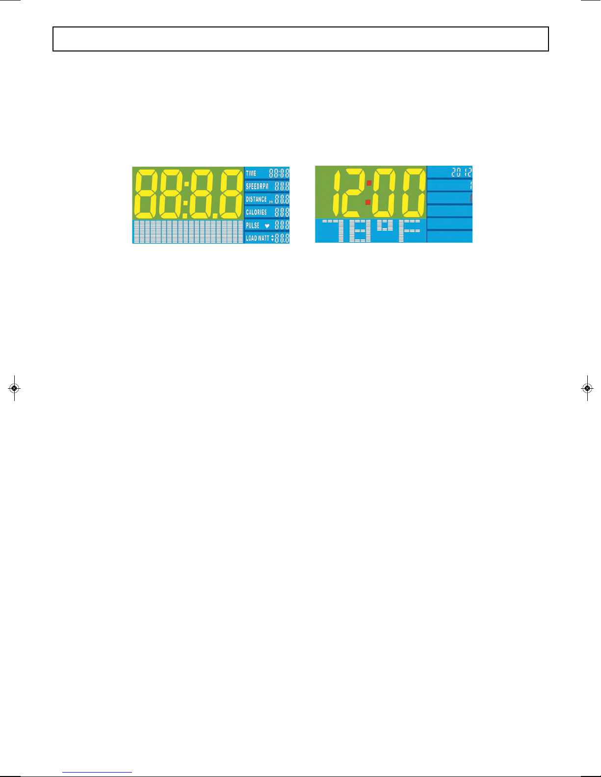
STEP 1:
INITIAL SET-UP
When the power supply is plugged into a wall outlet for the first time, the computer console will power up
with a brief test mode. Following the test mode, the console will wait for input to set the date and time.
Figure 1 Figure 2
Setting the clock: Using the round dial on the console, the year, month and day will be entered. Turn the
dial clockwise (CW) or counterclockwise (CCW) to adjust the numbers up or down. Once the correct
number is displaying, the dial can be pressed as a button to set the information.
In all programming modes, the item that is to be set will flash to prompt for user input. Once the item is set
and the round dial has been pressed to confirm the setting, the console will then display the next item to
adjust by flashing that item. Following the final entry of the minutes on the clock, the console will flash for
the Exercise Program choice.
BUTTON FUNCTIONS
ENTER Dial:
This dial is multi-functional. The dial can be rotated clockwise (CW) and counterclockwise (CCW) to
select functions and set parameters. This dial can also be depressed to function as an Enter button. Using
this dial as a button by pressing the round dial will confirm each action when setting the console.
RESET:
Pressing the Reset button for 2 seconds will fully reset the Console for the next workout returning all
values to zero. This will not reset the time or date settings. To reset time/date settings, unplug the power
supply from the wall for 3 settings and then plug in again. Refer to instructions above at that point.
START/STOP:
Use the Start/Stop button to Start, Stop or Pause the console.
RECOVERY:
To test your heart rate recovery status. At any point in your workout, you can press the recovery button to
check your fitness. The computer will set a preset time for you to let your heart rate return to a normal
level. You must hold your hands on the heart rate sensors while the computer counts down to zero at which
point it will display the results.
- 14 -
4/ GETTING STARTED - COMPUTER
helix manuals_Helix H1000 - lowres 26/06/2013 13:11 Page 14

- 15 -
4/ GETTING STARTED - COMPUTER
CONSOLE FUNCTIONS:
TIME: Counting up - No preset target. The timer will count up from 00:00 to maximum 99:59.
Counting down - The timer will count down from the users preset time.
SPEED: Displays the current training speed.
RPM: Displays the current training cadence. This track the number of rotations per minute.
DISTANCE: Displays the distance. It can be set to count up - No preset target. The distance will count up
from 0.00 to maximum 99.90
It can be set to count down - The distance will count down from the users preset distance.
See “Setting the Time, Distance, Calories, and Pulse on page 13.”
CALORIES : Displays the Calories. It can be set to count up- No preset target. The calories will count up
from 0 to maximum 990.
It can be set to count down – The Calories will count down from the users preset distance.
See “Setting the Time, Distance, Calories, and Pulse on page 13.”
PULSE: The monitor can detect chest pulse and the hand pulse when you wear on the chest belt or hold on
handgrip sensors, and the chest pulse is the priority.
WATT : Displays the current training resistance in watts; a measure of energy.
RECOVERY : After exercising for a period of time, keep holding on handgrips and press ‘RECOVERY’
button. All function display will stop except ‘TIME’ starts counting down from 00:60 to 00:00. Screen will
display your heart rate recovery status with the F1,F2 ... to F6. F1 is the best, F6. F6 is the worst. User may
keep exercising to improve the heart rate recovery status. (Press the RECOVERY button again to return
the main display.)
TEMPERATURE : Displays the room temperature in sleep mode.
CALENDAR: Displays year/month/day in sleep mode.
CLOCK : Displays time in sleep mode.
Notes:
The monitor display will go into sleep mode automatically if
you stop training for 4 minutes. It will appear as figure 3 right.
Figure 3
You may press any button to awake the monitor display, and the previous training data will appear.
When the training starts again, the data will keep accumulating from previous position.
helix manuals_Helix H1000 - lowres 26/06/2013 13:11 Page 15
4/ GETTING STARTED - COMPUTER
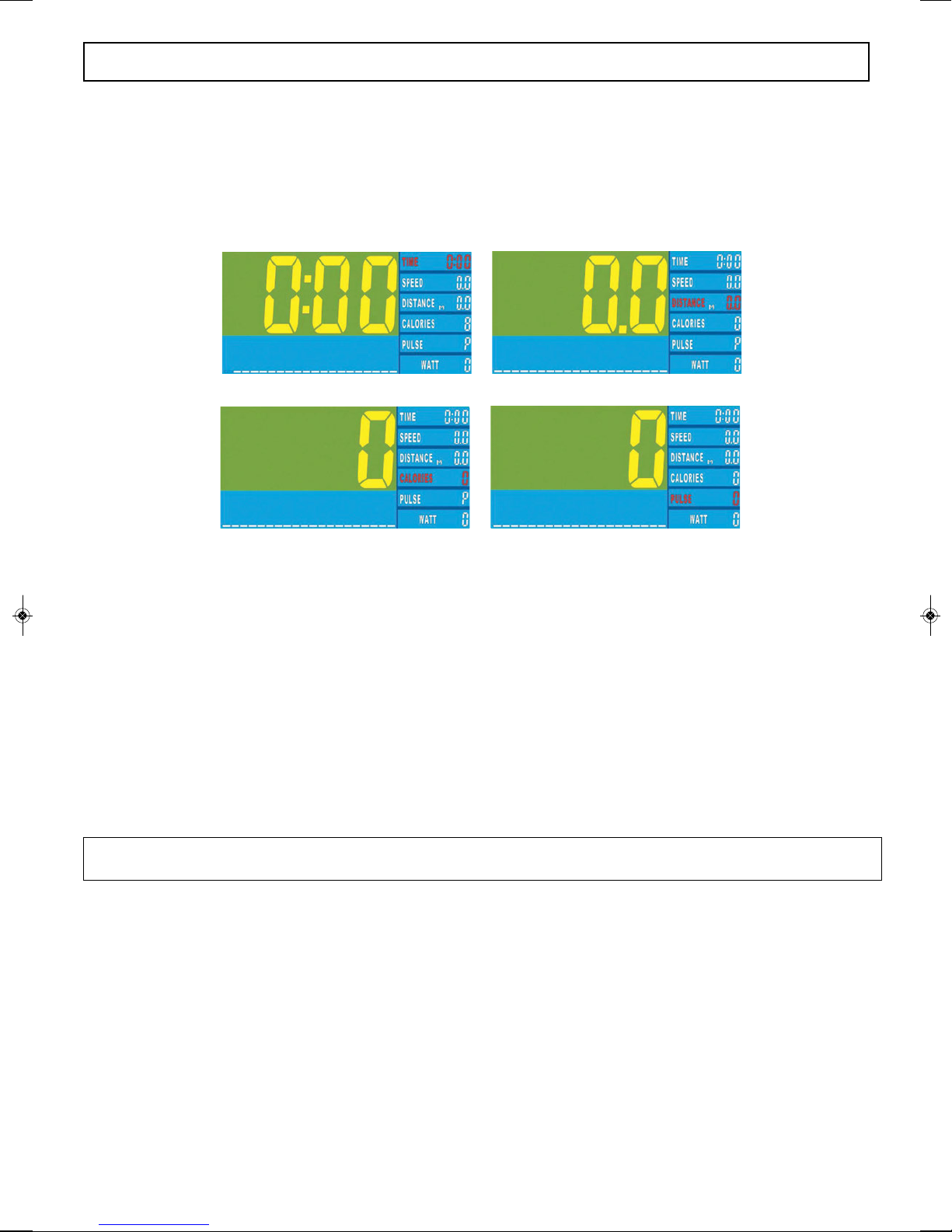
SETTING THE TIME, DISTANCE, CALORIES, AND PULSE IN EACH PROGRAM.
For each Workout Program, after the selection of the workout program, the computer will prompt the user to
select the TIME, DISTANCE, CALORIES or PULSE goal for the workout.
(Heart Rate Program HRC will not allow PULSE entry ).
The instructions below are universal for all programs. Some exceptions will be noted.
Figure 4 Figure 5
Figure 6 Figure 7
After following the instruction specific to setting each workout program, the next step will be to select the
workout session goals such as time, distance, calories or pulse. By selecting time, when the TIME is
flashing, the user can rotate the dial to set the time to the chosen value. For example, rotate the dial until the
Time displays 15:00 and when the user presses the start button, the timer will begin the count down.
Alternatively, the user could choose to allow the time to begin counting at zero and allow another parameter
to control the duration of the workout. If the duration is to be controlled by the distance, when the time is
flashing the user should press ENTER and the Distance will begin to flash. Then the desired distance can be
set with the dial. When the distance desired is displayed, press ENTER. After pressing enter, the Calories
will flash. The workout can be controlled by multiple parameters. If the user would like to set a calories goal,
using the dial, adjust the calories to the desired goal then press enter. Next, the PULSE will flash. Again this
can be set as a goal as well by adjusting the PULSE goal with the dial and then pressing ENTER.
After all entries are complete, press Start to begin your workout.
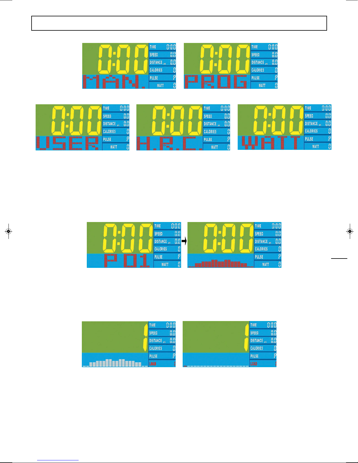
Program Profile Selection:
Following the first time console set-up ( Step 1 above), or upon resetting the console, the display will flash
to request the program selection. The available programs are: Manual ( MAN.), Program ( PROG),
USER ( USER), HRC (H.R.C.) and Watts (WATT). Each program is explained below. ( See Figure 4 )
When prompted by the flashing program section in the bottom left area, select a program by rotating the dial
clockwise (CW) and counter clockwise (CCW). Press the dial as a button to confirm that program selection.
If a program is not chosen and the start/stop button is pressed, the console will default to the Manual
program.
- 16 -
helix manuals_Helix H1000 - lowres 26/06/2013 13:11 Page 16
5/ COMPUTER BUTTON FUNCTIONS
- 17 -
Figure 8 Figure 9
Figure 10 Figure 11 Figure 12
Training in PROGRAM mode :
When PROGRAM (PROG) mode is selected, rotating the dial clockwise or counterclockwise selects one
of 12 programs. P01, through to P12. At each selection with a moment, the image in the bottom left screen
will change from the P01 to the program profile for a brief view of that program. When the desired program
is displayed, push the ENTER dial like you would a regular button and it will confirm the selection.
Figure 13 Figure 14
Following program profile selection, the LOAD will flash in the bottom right segment; rotate the dial to
select from level 1 to 16. When the desired load is selected, press the ENTER/MODE button to confirm.
At any time during the workout, the load can be adjusted by rotating the dial. Next, refer to the universal
instructions above to set the time, distance, calories or Pulse.
Figure 15 Figure 16
Training in MANUAL mode
Manual mode will be a flat profile that will not automatically change over time. Using the dial, the user can
increase the load (resistance) by rotating the dial clockwise and counterclockwise. The increase or decrease
in load will display in the bottom left section. When the desired load is displayed, press the dial to confirm
the selection. Next, refer to the universal instructions above to set the time, distance, calories or Pulse.
helix manuals_Helix H1000 - lowres 26/06/2013 13:11 Page 17

Training in USER PROGRAM:
User Program allows for a custom profile to be selected. Each segment of the workout is adjusted by
rotating the dial to increase or decrease the level for that segment.
After selecting USER by pressing the dial to confirm, the first column (segment) of the profile will begin
to flash. Adjust the resistance for that segment by rotating the dial. Then press the dial to confirm.
The next column/segment will then begin to flash. Again rotate the dial to select resistance level and press
enter to confirm. Repeat this process until all columns/segments have been confirmed. There are 20
segments in total, if at any point you are satisfied with the columns/segments you have set, you may press
and hold the ENTER button for 2 seconds to proceed and stop setting more columns/segments.
Training in Heart Rate Control (H.R.C.) mode:
H.R.C. mode allows the user to set a desired Heart Rate setting based on their age. This will control the
resistance and set the resistance based on your heart rate while exercising. This can be set to a percentage
of maximum heart rate based on your age. The settings are 55:%, 75%, 90% of maximum heart rate or a
specific heart rate by using TARGET and then setting the actual target heart rate.
Programming in this mode:
After confirming H.R.C. mode, the AGE 25 will be flashing on the screen. Set your age by rotating the dial
CW or CCW until your age is displayed. Then press the ENTER button to confirm. The screen will then
request the percentage of maximum heart rate you wish to be your training level; such as 55%, 75%, 90%
and TARGET. Target will allow you to enter a specific heart rate goal. Rotate the dial CW or CCW to
select the heart rate percentage. (See Figure 17) The monitor will then calculate the preset heart rate value
automatically according to the age you have entered and the training level you’ve chosen.
Next, refer to the universal instructions above to set the time, distance, calories or Pulse.
Figure 17 Figure 18
Training in WATT mode :
After selected the Watt program, the preset watt value of 120 will be flashing. Rotate the dial to set the
target value from 10 to 350 watts.
Next, refer to the universal instructions above to set the time, distance, calories or Pulse.
5/ COMPUTER BUTTON FUNCTIONS
- 18 -
helix manuals_Helix H1000 - lowres 26/06/2013 13:11 Page 18

- 19 -
helix manuals_Helix H1000 - lowres 26/06/2013 13:11 Page 19

For customer service, we first recommend you contact the dealer where you purchased the Helix.
They will be able to resolve any issues the fastest.
If you cannot reach the dealer, please feel free to contact Helixco at
Distributed under license from Kriptonite Corp by Helixco, a division of M & S Distribution, Inc, 136 Arlington Street, Boston, Ma 02116
This product is patented in the US and other International Patents and patents pending.
US Patent Number 7,108,638
Helix® is a registered trademark of M & S Distribution, Inc. All rights reserved.
helix manuals_Helix H1000 - lowres 26/06/2013 13:11 Page 20
Other manuals for H 1000 ESPRIT
2
Other HELIX Fitness Equipment manuals


Popular Fitness Equipment manuals by other brands


Precor
Precor Resolute RSL 606 Getting started guide

Hoist Fitness
Hoist Fitness CFG-3753 owner's manual

Gratz Pilates
Gratz Pilates LADDER BARREL Assembly instructions

ParaBody
ParaBody 867101 Assembly instruction sheet

BLK BOX
BLK BOX WEIGHTS TREE Owner's manual & quick start guide

Gymrex
Gymrex GR-BE 150 user manual


