Helmut BSC350 User manual

EN|RU
ИНСТРУКЦИЯ ПО ЭКСПЛУАТАЦИИ
01/2014
www.helmutworld.com/support
CONCRETE CUTTER BSC350/BSC350H

OPERATION MANUAL CONCRETE CUTTER
A WARNING
To reduce the risk of injury, all operators and maintenance personnel must read and
understand these instructions before operating, changing accessories, or performing
maintenance on this power equipment. All possible situations cannot be covered in these
instructions. Care must be exercised by everyone using, Maintaining or working near this
equipment.
«Helmut» в России
Телефон : 8 (495) 518-94-22
E-mail: [email protected]
www.helmutworld.com

3
1 RULES FOR SAFE OPERATION WARNING:
Failure to follow instructions in this manual may lead to serious injury or even death! This
equipment is to be operated by trained and qualified personnel only! This equipment is
for industrial use only.
The following safety guidelines should always be used when operating these Concrete
Cutters:
GENERAL SAFETY
■DO NOT operate or service this equipment before reading the entire manual.
■This equipment should not be operated by persons under 18 years of age.
■NEVER operate this equipment without proper protective clothing. Shatterproof
glasses, steel-toed boots and other protective devices required by the job.
■NEVER operate this equipment when not feeling well
due to fatigue, illness or taking medicine.
■NEVER operate this equipment under the influence or drugs or alcohol.
■NEVER use accessories or attachments, which are not recommended by our
company for this equipment . Damage to the equipment and/or injury to user may result.
■The manufacturer does not assume responsibility for any accident due to
equipment modifications.
■Whenever necessary, replace nameplate, operation and safety decals when
they become difficult to read.
■ALWAYS check the machine for loosened threads or bolts before starting.
■NEVER touch the hot exhaust manifold, muffler or cylinder. Allow these parts to
cool before servicing engine or saw.
■High Temperatures - Allow the engine to cool before adding fuel or performing
service and maintenance functions. Contact with hot components can cause serous
bums.
■The engine section of this cutter requires an adequate free flow of cooling air.
NEVER operate the cutter in any enclosed or narrow area where free flow of the air is
restricted . If the air flow is restricted it will cause serious damage to the saw or engine
and may cause injury to people . Remember the cutter’s engine gives off DEADLY carbon
monoxide gas.
■ALWAYS refuel in a well-ventilated area, away from sparks and open flames.
■ALWAYS use extreme caution when working with flammable liquids. When
refueling, stop the engine and allow it to cool. DO NOT smoke around or near the
machine. Fire or explosion could result from fuel vapors, or if fuel is spilled on a hot
engine.
■NEVER operate the cutter in an explosive atmosphere or near combustible
materials. An explosion or fire could result causing severe bodily harm or even death.
■Topping-off to the fuel filler port is dangerous, as it tends to spill fuel.
■NEVER use fuel as a cleaning agent.

4
■ALWAYS read, understand, and follow procedures in operator’s Manual before
attempting to operate equipment.
■ALWAYS be sure to operator is familiar with proper safety precautions and
operating techniques before using the cutter.
■Stop the engine when leaving the cutter unattended.
■Block the unit when leaving or when using on a slope.
■Maintain this equipment in a safe operating condition at all times.
■ALWAYS stop the engine before serving, adding fuel and oil.
■NEVER Run engine without air filter. Severe engine damage may occur.
■NEVER Run engine without air filter. Severe engine damage may occur.
■ALWAYS service air cleaner frequently to prevent carburetor malfunction.
■ALWAYS store equipment propped when it is not being used. Equipment should
be stored in a clean, dry location out of the reach of children.
■NEVER operate this cutter in areas that contain combustible material or fumes.
Fire and/or explosions may result from errant sparks from the equipment.
WARNING:
■DO NOT operate this equipment unless all guards and safety devices are
attached and in place.
Caution must be exercised while servicing this equipment. Rotating and moving parts can
cause injury if contacted.
■Keep all inexperienced and unauthorized people away from the equipment at
all times.
■Unauthorized equipment modifications will void all warranties.
DIAMOND BLADE SAFETY
■Use appropriate steel centered diamond blades manufactured for use on
concrete cutters.
■ALWAYS inspect diamond blades before each use. The blade should exhibit no
cracks, dings, or flaws in the steel centered core and/or rim. Center(arbor)hole must be
undamaged and true.
■Examine blade flanges for damage, excessive wear and cleanliness before
mounting blade. Blade should fit snugly on the shaft and against the inside/outside blade
flanges.
■Ensure that the blade is marked with an operating speed greater than the blade
shaft speed of the cutter.
■Only cut the material that is specified by the diamond blade. Read the
specifications of the diamond blade to ensure the proper tool has been matched to the
material being cut.
■AIWAYS keep blade guards in place. Exposure of the diamond blade must not
exceed 180 degrees.
■Ensure that the diamond blade does not come into contact with ground or
surface during transportation. DO NOT drop the diamond blade on ground or surface.

5
■The engine governor is designed to permit maximum engine speed in a no-load
condition. Speeds that exceed this limit may cause the diamond blade to exceed the
maximum safe allowable speed.
CUTTER TRANSPORTATION SAFETY
■Use the lifting bail and appropriate lifting equipment to ensure the safe
movement of the cutter.
■DO NOT use the handle bars and/or front pointer as lifting points.
■NEVER tow the saw behind a vehicle.
■Ensum that both pointer bars are positioned appropriately to minimize their
exposure during transportation.
■Safeguard against extreme cutter attitudes relative to level. Engines tipped to
extreme angles may cause oil to gravitate into the cylinder head making the engine
difficult to start.
■NEVER transport the cutter with the blade mounted.
EMERGENCIES
■ALWAYS know the location of the nearest fire extinguisher and first aid kit.
Know the location of the nearest telephone. Also know the phone numbers of the
nearest ambulance, doctor and fire department. This information will be invaluable in the
case of an emergency.
MAINTENANCE SAFETY
■NEVER lubricate components or attempt service on a running machine.
■ALWAYS allow the machine a proper amount of time to cool before servicing.
■Keep the machinery in running condition.
■Fix damage to the machine immediately and always replace broken parts.
■Dispose of hazardous waste properly. Examples of potentially hazardous waste
are used motor oil, fuel and fuel filters.
■DO NOT use food or plastic containers to dispose of hazardous waste.

6
OPERATION
Introduction/Determining the Right Machine
Congratulations on your pumhase of our Cutter! You’ve made an excellent choice! Our
floor cutter has been specifically designed as the ideal machine for the professional
contractor who is engaged in concrete and asphalt flat sawing.
The machines used for the primary purpose of 'flat” sawing. This type of sawing is
described as “flat” because the pavement is cut somewhere close to a horizontal plane. It
is the most common type of diamond blade cutting.
Concrete cutters in the industry are available in a variety of types, sizes and styles, they
range from manual or self propelled in horsepower Ют 7-72hp. It is possible to cut both
concrete (green or cured, with or without rebar) or asphalt with a concrete cutter. Our
MF20 utilized for jobs requiring precision cutting including floors, pavements, walkways,
ramps and other flat sawing applications.
You will find a cutter to fit a wide vanety of job applications.
Upon receipt of your machine, CAREFULLY CHECK FOR ANY FREIGHT DAMAGE. Any
Damage should be immediately reported to the carrier and a claim registered.
Operating Principe/Delivery Checks/ Installing Blades/Types of Cutting.
OPERATING PRINCIPLE
The following instructions were compiled to provide you information on how to obtain
long and trouble free use of the unit. Periodic maintenance of this unit is essential. Read
the manual in its entirety and follow the instructions carefully. Failure to do so may injure
yourself or a bystander.
DELIVERY CHECKS
Immediately upon taking delivery of your new equipment and before puffing it into
service:
■Read the handbook completely--it could save a great deal of unnecessary
expense.
■Read the engine manual supplied.
■Check the general condition of the equipment-has it been damaged during
delivery?
■Check engine oil level.
■Check fuel levels.
Recommend lubricants are detailed in the CARE AND MAINTENANCE section.

7
INSTALLING BLADE
1. Be certain that the spark plug is disconnected or saw is unplugged.
2. Remove the blade shaft nut, and take off outside blade shaft flange.
3. Clean off any foreign particles on the clamping surfaces of flanges and on the
mounting surface of the blade.
4. Place the blade on the blade shaft, lining up the offset ' drive pin in the blade
with the drive pin in the mounting collar (if the pin system is available on the machine). If
your blade has a directional rotational arrow, position arrow for down cut (diamond tail
trailing for down cut).
5. Replace the outside blade shaft flange on the blade shaft. Drive pin on the
inside collar must project through the drive hole in the blade and into the outside collar
(if the pin system is available on the machine).
6. Tighten the blade shaft nut securely against star washer and outside flange,
using wrench supplied.
7. Reconnect the spark plug or (with switch “off”)plug in the electric supply cord.
TYPES OF CUTTING
Cut speed depends entirely on using the correct blade for the material to be cut. Wet or
dry. diamond blades of various specifications are available for cutting concrete or
asphalt.
Before Starting/Cold Start/Hot Start/
To Start Cutting
BEFORE STARTING
1. Use correct blade for cutting conditions.
2. Ensure arbors and flanges are clean and undamaged.
3. Mount blade and tighten securely using wrench.
4. When wet cutting, check water jets for adequate flow.
5. Align pointer with cutter blade.
Caution - Set unit up in an open area. Avoid close proximity to structures or other
equipment. Failure to do so may cause inadvertent Injury to operator or other persons in
the area.
Cold start-Open the fuel valve under the gas tank all the way. Position the engine stop
switch, located on the engine, to run. Open the throttle approximately halfway and apply
the choke. Pull the starter rope sharply. When the engine starts, open the choke and
adjust the throttle as necessary to keep it running. Allow the engine to warm up for a few
minutes before placing it under the load, if the engine doesn’t start after(3)pulls, open
choke slightly to prevent flooding. Always operate the engine at full throttle when under
load.

8
Hot Start-open the valve under the gas tank all the way if it has been shut off. Open the
throttle approximately half way. Do not apply the choke. Pull the starter rope sharply
until the engine starts. When the engine starts, adjust the throttle. Always operate the
engine at full throttle when under load.
NOTE: These starting instructions are general guidelines only. Since many engine options
are available, consult the Engine Manual included with this unit for specific instructions.
Caution-Gasoline Englnes-TO improve the engine service life, allow the engine to idle
without load for (2) to (5) minutes before shutting it down. When the idling period is up,
use the stop switch located on the engine and turn it to stop. Close the fuel valve under
the gas tank. Engine flooding can occur if the valve is left open during transport.
TO START CUTTING
1. Start engine and let engine warm up. All cutting is done at full throttle.
2. Align blade and cutter with cut. If wet cutting, open water valve and turn water
safety switch on.
3. Step on the left side of PEDAL until hear a “click”, then turn on the WHEEL
HANDLE on the top of the machine to remove the equipment forward and reverse, step
down the right side of PEDAL to change to “push” driving system.
4. Lower blade into cut slowly.
5. Cut as fast as blade will allow. If blade climbs out of cut, reduce forward speed
or depth of cut.
6. Use only enough side pressure on cutter handles to follow cutting line.
CUTTING
Lower the blade into concrete to required depth by turning the tilt crank
counterclockwise. Ease the saw slowly forward. Slow forward pressure if the saw begins
to stall.
Note: For deeper cuts(4 inches/102mm or more), several cuts should be made in
incremental steps of 1-1/2 inch (38mm) to 2 inches(51mm) until the desired depth is
reached.
Push the saw steadily forward using the front pointer as a guide. Exert enough forward
pressure so that the engine/motor begins to labor, but does not slow down. If the saw
begins to stall, retard forward movement until full RPM is restored to the blade. If saw
stalls, raise the blade out of the cut before restarting. Avoid excessive side pressure or
twisting of the blade in the cut.

9
BELTS&PULLEYS
NEVER MAKE ADJUSTMENTS TO V-BELTS AND PULLEYS WHILE ENGINE IS RUNNING
1. The best tension for a v-belt drive is the lowest tension at which the belts will
not slip under full load.
2. Take up tension until the belts are snug in the grooves. Run the drive for about
five (5) minutes to “seat" the belts. The impose the peak load. If the belts slip, tighten
them until they no longer slip at peak load. Most new belts will need additional
tensioning after seating.
3. Remember, too much tension shortens belt and bearing life.
4. Check the belt tension frequently during the first day of operation. Check the
belt tension periodically thereafter and make any necessary adjustments.
5. The two most common causes of sheave misalignment are:
-the engine drive shaft and the blade shaft are not parallel.
-the pulleys are not located properly on the shafts.
6. To check alignment, use a steel straight edge. See Figure 1.
Fig.1
7. Line up the straight edge along the outside face of both pulleys shown in the
drawing. All pulleys have (2) set screws in the bottom of their grooves. Set screws require
thread locking lock title.

10
8. Misalignment will show up as a gap between the pulley face and straight edge.
Make sure there is clearance between arbor pulley and saw base on both sides.
DRY CUTTING
• Never operate any saw without safety guards in place.
•Do not exceed maximum operating speed established for blade diameter.
•Do not force blade into material: allow blade to cutat Its own speed.
•Do not make long continuous cuts. Never dry cut for more than 30 seconds
at s time. Allow blade to cool.
•Do not cut or grind with side of blade or cut a curve or radius. Do not cut dry
with blades recommended for wet cutting.
•Do not operate saw with blade diameter larger than machine’s capacity.
IV LUBRICATION AND SERVICE
•Check oil levels, wiring, hoses (air, fuel, water) and lubricate machine daily.
•Repair or replace all worn or damaged components immediately.
•Check drive belt tension, do not over-tension.
•Make sure machine has full set of matched belts.
•Check blade shaft, make sure arbor and threads are not worn, damaged, or
bent.
•Blade shaft bearings should be tight, no free play side-to-side or up and down.
•Grease blade shaft bearings daily.
•Blade collars should be clean, free of nicks and burrs. No diameter wear and not
out of round.
•Drive pin not excessively worn or bent and free of gouges.
•All guards in place and secure.
•All fasteners tight and secure.
•Air filter/oil filter (hydraulic or engine)clean.
•Flush clean water through the pump and spray the assembly every night. This
prolongs the pump and blade life.
These products are covered by warranty for a period of six (6) months from the date of
purchase against defects in material or workmanship provided that:
•The product concerned has been operated and maintained in accordance with
the operating instructions.
•Has not been damaged by accident, misuse or abuse.
•Has not been tampered with or repaired by any unauthorized person.
The owner is responsible for the cost of transportation to and from the authorized
repairer and the unit is at the owners risk while in transit to and from the repairer.
Lubricants:
-Engine oil SAE 10W/30
-General Grease #1 Lithium

11
•Clean machine before starting lubrication maintenance.
•Insure machine is on solid, level ground before starting maintenance.
•During lubrication maintenance insures strict cleanliness is observed at all
times.
•To avoid the risk of accidents, use the correct tool for the job and keep tools
clean.
•The draining of engine oil is best carried out when the oil is warm NOT hot.
•Any spilled oil must be cleaned up immediately.
•Use only clean containers for oil and only CLEAN, FRESH oils and grease of
correct grade.
•Contaminated Waller/Fluids/oils/Filters Must Be Disposed of Safely.
12
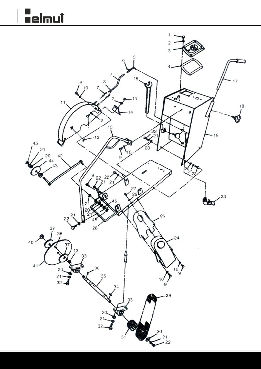
Major Components

13
Major Components
ITEM NO.
PART NO.
DESCRIPTION
QTY
1
2010101
BOLT M8*25
3
2
2010102
WASHER 8
5
3
2010103
INJECTION MOUTH
1
4
2010104
SEAL RING
1
5
2010201
ELBOW
1
6
2010202
COCK
1
7
2010203
PLASTIC PIPE
3
8
2010204
TEE
1
9
2010301
BOLT M10x25
6
10
2010302
WASHER 10
5
11
2010303
BLADE GUARD
1
12
2010304
NUT(BUTTERFLY)M10
1
13
2010305
NUTM8
2
14
2010306
PROTECTIVE MAT
1
15
2010401
LIFTING HOOK
1
16
2010401
WRENCH
2
17
2010601
HANDLE
2
18
2010602
KNOB
3
19
2010701
WATER TANK
1
20
2010702
WASHER 12
15
21
2010703
SPRING WASHER
13
22
2010704
BOLT M12x30
10
23
2010705
COCK
1
24
2010801
BELT GUARD
1
25
2010802
INNER GUARD
2
26
2010901
WASHER 6
1
27
2010902
SCREW M6x12
1
28
2010903
BASE ASSY
1
29
2010904-1
BELT FOR DIESEL ENGINE
3
2010904-2
BELT FOR PETROL ENGINE
3
30
2010101
WASHER
1
31
2010102
PULLEY,AXIS
1
32
2010103
BOLT M12x45
4
34
2010105
KEY 8x35
4
34
2010105
KEY 8x35
4
35
2010106
PRINCIPAL AXIS
1
36
2010107
PIN 6x10
1
37
2010108
BLADE FLANGE (INNER)
2
38
2010109
PIN
1
39
2011011
BLADE FLANGE (OUTER)
40
2011012
NUT
1
41
2011013
BLADE
1
42
2011101
POINTER
1
43
2011102
NUT
44
2011103
POINTER WHEEL
45
2011104
NUT M12
1

14
Transmission Assy

15
Transmission Assy
ITEM NO.
PART NO.
DESCRIPTION
QTY
1
2020101
BOLT M8*25
6
2
2020102
WASHER 8
5
3
2020103
WHEEL HANDLE
1
4
2020104
BOLT M 10x30
6
5
2020105
WASHER10
5
6
2020106
BEARING ASSY.
2
7
2020107
KEY 6x30
2
8
2020108
MAIN SHAFT
1
9
2020109
STEM
1
10
2020110
SPRING WASHER M10
1
11
2020111
NUT M10
1
12
2020201
PEDAL
1
13
2020202
LEVER
1
14
2020301
PROTECTIVE PLATE
1
15
2020401
WASHER M10
16
2020402
KEY 10x40
1
17
2020403
WASHER 35
1
18
2020404
KEY 8x40
1
19
2020405
SLEEVE FOR CLUTCH
1
20
2020406
BEARING ASSY.
2
21
2020407
LEFT WHEEL
1
22
2020408
WASHER 12
4
23
2020409
SPRING WASHER 12
4
24
2020410
BOLT M12x40
4
25
2020411
REAR AXIS
1
26
2020412
WORM
1
27
2020413
SLEEVE, WORM
1
28
2020414
RIGHT WHEEL
1

16
Depth Adjusting Assy

17
Depth Adjusting Assy
ITEM NO.
PART NO.
DESCRIPTION
QTY
1
2030101
PULLING NUT
3
2
2030102
SPRING PIN 4 x 16
1
3
2030103
SPRING
2
4
2030104
PIN
1
5
2030201
WHEEL HANDLE
1
6
2030202
BOLT МЮхЗО
1
7
2030203
WASHER10
1
8
2030204
BOLT M8*25
1
9
2030205
WASHER8
1
10
2030206
BOLT M8*12
1
11
2030207
BEARING ASSY.
2
12
2030208
POSITION PLATE
2
13
2030209
SCREW STEM
1
14
2030210
CONNECTING STEM
1
15
2030211
NUT M10
4
16
2030301
RIVET
4
17
2030302
SCALE
3
18
2030303
POINTER
1
19
2030401
SPRING
1
20
2030402
CONNECTING PIPE
1
21
2030403
WASHER 12
1
22
2030404
BOLT M12*70
1
23
2030501
NUT M12
1
24
2030502
BOLT M12*10
ф
2
25
2030601
BEARING ASSY.
2
26
2030602
SPRING WASHER 10
2
27
2030603
BOLT
1
28
2030604
WASHER
1
29
2030605
WHEEL
1
30
2030606
WHEEL RACK MODULE
1

18
Engine Assy

19
ITEM NO.
PART NO.
DESCRIPTION
QTY
1
2040101
FIXING PLATE
1
2
2040102
CONNECTOR
1
3
2040103
CABLE
1
4
2040104
CABLE PIPE
1
5
2040105
SCREW M16*25
1
6
2040106
WASHER M6
1
7
2040107
THROTTLE CONTROL
.1
8
2040201-1
DIESEL,KAMA 186
1
2040201-2
PETROL, 188F
1
2040201-3
PETROL,EH36D
1
2040201-4
PETROL,HONDA GX390K1
1
9
2040202-1
KEY FOR DIESEL ENGINE
1
2040202-2
KEY FOR PETROL ENGINE
1
10
2040203-1
PULLEY FOR DIESEL
ENGINE
1
2040203-2
PULLEY FOR CHINESE
PETROL ENGINE
1
2040203-3
PULLEY FOR ROB1N
ENGINE
1
2040203-2
PULLEY FOR HONDA
ENGINE
1
11
2040204
WASHER M8
12
2040205
SPRING WASHER M8
1
13
2040206
BOLT M8x25
1
14
2040301
BOLT M10*40
4
15
2040302
SPRING WASHER M10
6
16
2040303
WASHER M10
6
17
2040304
NUT M10
2
18
2040305
BASE PLATE
1
19
2040306
BOLY M16x10
1
20
2040307
NUT M16
1

20
Electric Starter Assy
This manual suits for next models
1
Table of contents
Languages:
Popular Cutter manuals by other brands

TE
TE REC-Li250M user manual

Logan Graphic Products
Logan Graphic Products 709-1 instructions

Miller Electric
Miller Electric Spectrum Thunder owner's manual

Lincoln Electric
Lincoln Electric Torchmate 5100 Series quick start guide

Westfalia
Westfalia TC 180 J 11 instruction manual

CASTLE
CASTLE TSM-22 owner's manual

Parkside
Parkside 270700 Translation of the original instructions

ecobra
ecobra 770660 operating instructions

Makita
Makita 4112HS instruction manual

Textron
Textron Klauke ES 20RMCCFB manual

Ilco Orion
Ilco Orion NOVA 2000 operating manual

Quality Commercial Macines
Quality Commercial Macines QCM-8200M user manual


