INSTALLATION AND OPERATING INSTRUCTIONS
710-0143 Custom IS Installation Manual with Low EMR
07/18/16 Rev 02
Page 7
WARNING
SECTION 2: INSTALLATION SUMMARY AND TIPS
ELECTRICAL: ROUGH IN:
Step 1: Is a traditional sauna heater being installed in room?
If yes, the traditional heater location must be chosen first. If the room is
over 78" and the heater is hung on the wall and the IR assembly can be
installed above the tradional sauna heater. There has to be 5" of
clearance above the traditional sauna heater and the bottom of the IR
assembly. See Diagram 1 for specific spacing requirements. If no,
proceed to step 2.
Step 2: What IS system should be installed in the room?
The system will determine how many IR emitters will be in the room.
See Diagram 7 for the quantities of IR emitters. Try to evenly space
the IR emitters in the room behind the benches. See Diagram 3 for IR
emitter size information.
Step 3: IR Panel Wire Installation
Pull 14-2 AWG wire w/ground BX cable from the CB PK Box to
closest IR emitter. Install a metal single gang junction box 24” below
the bottom of the estimated height of the IR heating panel. Daisy chain
the wire from the first IR emitter to the next junction box and continue
to loop and leave wires sticking out for each single gang box.
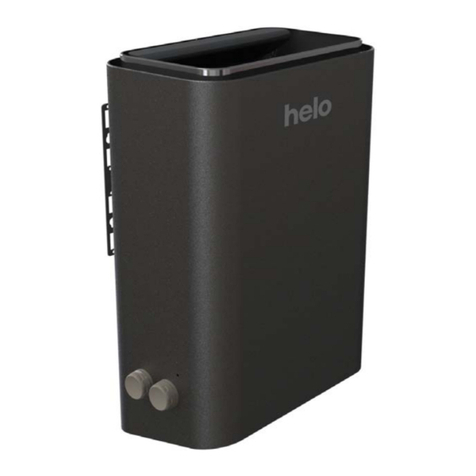
Step 4: Traditional Sauna Heater Wiring traditional sauna heater
(optional). Refer to Diagram 2 for the traditional sauna heater for wire
size or a 72" wire is provided with the sauna heater. Preinstall wire
from the CB PK box to the location of the bottom of the sauna heater.
A two conductor cable is provided with the sauna heater for the high
limit safety switch. Preinstall wire in the wall. The traditional sauna
system will not work if the wires and switch are not connected.
Step 5: Lighting Installation (Optional Equipment) SaunaLogic IS is
capable of operating ONLY a lighting package purchased with the
system. The lighting package consists of 3 color therapy lights, 2
interior lights, 3 exterior lights, and the cables to connect the light
assemblies to the CB PK box. The cables provided are 176" from CB
PK box to the first light fixture. Then the cable is 60" between the
fixtures. All cable lengths are similar depending on the number of
fixtures.
Predetermine light fixture locations in the ceiling based on cable
lengths and CB PK box location. Route the cable provided from the
desired light locations in the ceiling to the CB PK box before any
tongue and groove is applied.
Cut 2 3/4" holes in tongue and groove boards for light fixtures as the
tongue and groove is being applied. Ensure the lighting cables reach
the hole locations.
Refer to Diagram 1 for
minimum clearance of
ceiling above heater.
Fire sprinkler systems used
inside any sauna room
should be properly rated for
sauna room temperatures.
Do not spray water on
Infrared Emitters
Water use on Infrared
Emitters may cause damage
and will void warranty.
Do not install a shower in the
sauna room.
Electric Shock Hazard - High
voltage exists within this
equipment. There are no
user serviceable parts in this
equipment.
All installation and service to
this equipment should be
performed by qualified
licensed personnel in
accordance with local and
national codes.
Use only copper wire of the
size and type indicated in the
Heater Specification Chart
and the temperature rating
indicated on the heater
junction box.
All heaters and controls must
be grounded per NEC to
prevent electrical shock in
case of unit failure.
Electrical outlets or
receptacle must not be
installed in a sauna room.


