Henny Penny 6.10 Operating instructions

Service instructions
Combi Steamer
Unit Model Type of
energy
Unit type
Space$afer
Plus Platnium
6.10
Electric Tabletop
unit
Space$afer
Platnium
--
-
6.23 Electric Tabletop
unit
Translation from the original document • 10015160-0ASDE-A • 10/16/2015
10015160-0ASAE-A en-US
REGISTER WARRANTY ONLINE AT WWW.HENNYPENNY.COM

Manufacturer
Copyright by MKN Maschinenfabrik Kurt Neubauer GmbH & Co. KG
Halberstaedter Strasse 2a
D-38300 Wolfenbuettel
Telephone 0 53 31 / 89-0
Telefax 0 53 31 / 89-280
2 Service instructions

Directory of contents
1Password overview ............................................................ 5
2Introduction......................................................................... 6
2.1About this manual ............................................................................ 6
2.2Warranty............................................................................................ 6
3Safety instructions ............................................................. 7
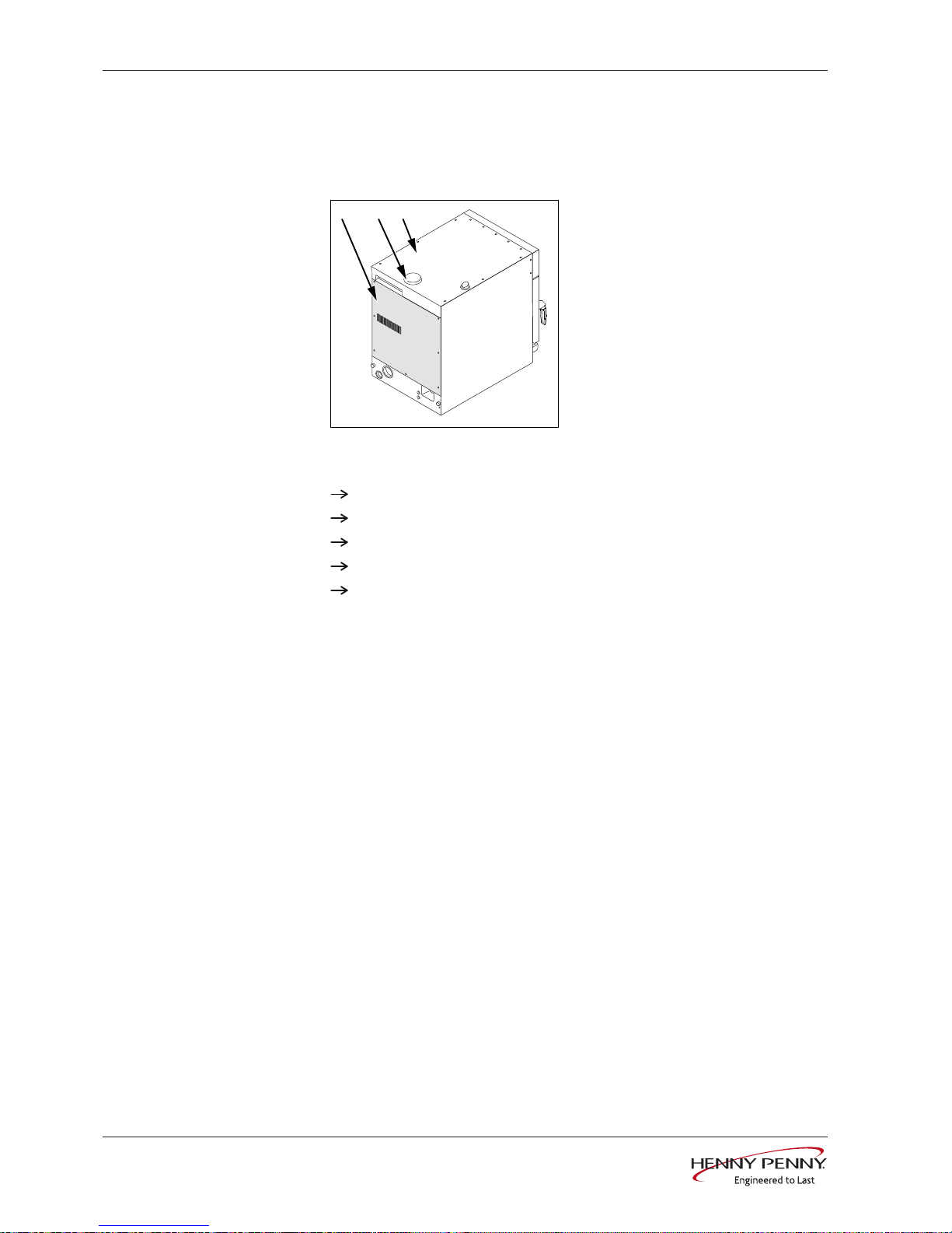
4Opening the appliance....................................................... 8
4.1Unit cover and rear wall................................................................... 8
5Service menu - appliance test........................................... 9
5.1Service menu .................................................................................... 9
5.1.1Calling up the service level........................................................................ 9
5.1.2Service menu overview ............................................................................. 9
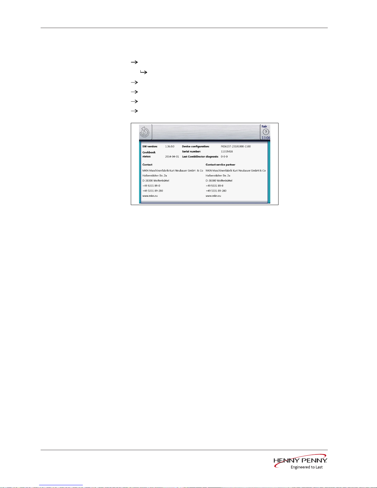
5.2Appliance information.................................................................... 10
5.3Status overview .............................................................................. 11
5.4CombiDoctor................................................................................... 12
5.5Relay test ........................................................................................ 14
5.6WaveClean test (option)................................................................. 16
5.7100°C + core temperature calibration........................................... 17
5.7.1Check calibration..................................................................................... 18
5.7.2Calibrate cooking chamber sensor.......................................................... 19
5.8DynaSteam test .............................................................................. 20
5.9Emptying the water ........................................................................ 21
5.10Setting the set-up height ............................................................. 21
5.11Audio settings .............................................................................. 22
5.12Select signal tones....................................................................... 23
5.13POS activation .............................................................................. 23
5.14Log data export ............................................................................ 23
5.15Software update ........................................................................... 25
5.16Importing additional content....................................................... 25
5.17Restoring data .............................................................................. 26
5.18Backing up data............................................................................ 26
5.19Water filter maintenance.............................................................. 27
5.20Importing contact data................................................................. 27
5.21Setting units.................................................................................. 28
5.22Backup relay ................................................................................. 28
5.23Status overview direct access .................................................... 29
6Software ............................................................................ 31
6.1Software update ............................................................................. 31
6.2Importing additional content......................................................... 33
6.3Importing the manufacturer's cookbook...................................... 35
10015160-0ASAE-A
3Service instructions

Directory of contents
4 Service instructions
7Trade show mode............................................................. 37
8Electronics ........................................................................ 38
8.1Block diagram for the control ....................................................... 38
8.1.1Unit size 6.23........................................................................................... 38
8.1.2Unit size 6.1............................................................................................. 38
8.2Control board.................................................................................. 39
8.2.1Layout...................................................................................................... 39
8.2.2Configuration ........................................................................................... 40
8.3Safety overview .............................................................................. 43
8.3.1Unit size 6.23........................................................................................... 43
8.3.2Unit size 6.1............................................................................................. 44
9Error messages ................................................................ 45
9.1Emergency operation..................................................................... 45
9.2Cooking chamber sensor defective (694, 695) ............................ 46
9.3Core temperature sensor defective (699, 700)............................. 47
9.4Water vapor sensor defective (710).............................................. 48
9.5Excess temperature in the cooking chamber (ID73)................... 49
9.6Overtemperature control (TMP_ID2)............................................. 50
9.7Risk of frost (TMP_ID72)................................................................ 50
9.8Fan defective or temperature limiter triggered (702) only for
Compact ................................................................................................ 51
9.9Fan defective. Cooking program was cancelled (701)................ 53
9.10Water pressure too low (709) ...................................................... 53
9.11Faulty CAN connection................................................................ 55
10015160-0ASAE-A

Password overview
5Service instructions
1 Password overview
Range Pass-
word
Description Described in
Installation / com-
missioning
2100 Setting all basic parameters
(for example time / date).
Installation in-
structions
CO2 gas calibra-
tion
999 Verification and calibration of
exhaust emissions. Only for
energy type - gas.
Installation in-
structions
Network settings 2100 Input network addressing.
Only for units with touch-
screen control.
Installation in-
structions
Basic settings /
user
111 Setting of basic values for the
user, functions, software up-
date.
Operating in-
structions
Lockscreen 369 Deactivating the lockscreen
in cooking mode. Only for
units with touchscreen con-
trol.
Operating in-
structions
Trade show mode 888 Activation / deactivation for
exhibition mode.
Service instruc-
tions
Service menu 1967 Service range for authorized
service technicians.
Service instruc-
tions
10015160-0ASAE-A

Introduction
6 Service instructions
2 Introduction
2.1 About this manual
This service manual contains information needed by the service
technician for professional and correct fault isolation, repair and
maintenance of the unit. The service technician must also observe
the contents of the installation instructions and the user manual.
Target group Target group for this service manual is trained specialists who are
familiar with the technical functioning and operation of the unit.
Figures All figures in this service manual are intended as examples.
Discrepancies can arise between this and the actual unit.
2.2 Warranty
The warranty is void and safety is no longer assured in the event of:
•Modifications or technical changes to the unit,
•Improper use,
•Incorrect startup, operation or maintenance of the unit,
•Problems resulting from failure to observe these instructions.
10015160-0ASAE-A

Safety instructions
7Service instructions
3 Safety instructions
For servicing tasks, the service technician must be familiar with and
observe regional regulations.
In addition, the notes in the service manual must be observed.
DANGER Danger to life due to electric current
üDisconnect power prior to performing gas and electrical work.
• Disconnect unit from the mains supply and secure it against restart.
• Check to ensure absence of voltage.
DANGER Risk of fatal injury from gas
üDisconnect the unit from gas supply prior to performing gas installation
tasks.
• Lock site gas supply and secure it against restart.
10015160-0ASAE-A

Opening the appliance
8 Service instructions
4 Opening the appliance
4.1 Unit cover and rear wall
Overview
a b c
a Rear panel c Unit cover
b Air inlet nozzle cover
Remove unit cover Remove cover from air inlet nozzles by turning it.
Remove the screws from the unit cover.
Remove the unit cover.
Remove the rear panel. Remove screws from the rear panel.
Remove the rear panel.
Mounting Mounting is done in the reverse order.
10015160-0ASAE-A

Service menu - appliance test
9Service instructions
5 Service menu - appliance test
5.1 Service menu
Description • Functional testing of individual components
•Error analysis
•Maintenance
•Change basic settings
•Software update
The graphics shown may deviate due to changes and different
software versions.
5.1.1 Calling up the service level
Calling up the Service menu
Switch the appliance on.
Touch the "Appliance functions" field.
Display of
Appliance functions
menu.
Touch "Settings" field.
Display of
PIN
window.
Enter password and touch
Confirmation
field.
Display of menu
Appliance test (Service menu)
.
INFORMATION
The password for the service menu is 1967
5.1.2 Service menu overview
Selecting a menu element Display of the menu elements in the left area.
Page change by swiping upward/downward.
Select menu element by touching.
10015160-0ASAE-A

Service menu - appliance test
10 Service instructions
5.2 Appliance information
Description Display of the appliance-specific information
Installed software
Appliance configuration
Cookbook version
Serial number
Contact data
Overview
Exiting the appliance
information
Touch the
Back
field.
10015160-0ASAE-A

Service menu - appliance test
11Service instructions
5.3 Status overview
Status 1
Heating circuit
PWM: heat requirement in %.
POS: power optimization system (option).
Temperature sensors B1, B3, B6, B7 are not present.
Status 2
Climate control system, fan
B14: Pressure switch on the DynaSteam unit
PWM: heat requirement in %.
Temperature sensor B3 is not present.
No indicator of fan speed for unit size 6.23.
Status 3
WaveClean (option)
K04: Magnetic valve for water vapor elimination & siphon filling
B15: Reed contact switch
B14: Pressure switch on the DynaSteam unit
Temperature sensor B3 is not present.
10015160-0ASAE-A

Service menu - appliance test
12 Service instructions
Status 4
Miscellaneous
K3: Manual rinse
K10: Motor M1 On/Off. Only for unit size 6.23.
B15: Reed contact switch
K07, K13, K14: Not used
Temperature sensors B1, B3, B6, B7 are not present.
5.4 CombiDoctor
Description The CombiDoctor offers an automatic check of the climate control
and the WaveClean automatic cleaning. The tests are possible
individually or as overall test. For instructions on performing, see the
touch screen.
Overview
Selecting a program Select a program by adjusting the roller.
Program description 1 Climate
Automatic checking of the following areas/components
•Heating circuit
– Heating body, failure of a phase (only for energy type electric)
– Semiconductor relay SSR (only for energy type electric)
– Gas system (only for energy type gas)
– Temperature control
– DynaSteam steaming unit
– Air inlet flap
10015160-0ASAE-A

Service menu - appliance test
13Service instructions
2 WaveClean
•Automatic checking of the WaveClean cleaning
– WaveClean pump (circulation pump)
– Siphon pump (drainage pump)
– Magnetic valve for water vapor elimination & siphon filling
– Reed contact switch of the cooking chamber door
Starting the program Touch the "START" field.
Evaluation The test result appears on the touch screen.
Entry in HACCP memory.
10015160-0ASAE-A

Service menu - appliance test
14 Service instructions
5.5 Relay test
Description Separate control of the relay.
Testing the relay.
Testing the connected components.
INFORMATION Relays K1 and K16 are switched on permanently.
A plurality of relays are switched on simultaneously.
Overview
Image: Relay test page 1
Image: Relay test page 2
Activating relay test Touch field of relay to be tested.
The relay is active.
Field of the active relay is highlighted in green.
Deactivating relay Touch field to be deactivated that is highlighted in green.
The relay is inactive.
Field is highlighted in gray.
10015160-0ASAE-A

Service menu - appliance test
15Service instructions
Relay overview Relay Connec-
tor
No. Description Informa-
tion
K1 X10 2 Main contactor Q1 230V AC
K1 X11 1 POS A 230V AC
K2 X11 2 POS B 230V AC
K3 X12 2 Magnetic valve K23 for manual
rinse
230V AC
K4 X12 3 Magnetic valve for water vapor
elimination K12
230V AC
K5 X12 4 Siphon pump G24 230V AC
K6 X12 5 Backup relay K6 230V AC
K7
Not in use
K8 X17 1 Solenoid fresh air M8 230V AC
K9 X16 1-3 Only for unit size 6.23: fan direc-
tion left/right
Potential-
free
K10 X13 1/2 Only for unit size 6.23: fan on/off Potential-
free
K11 X14 2 Cooling fan G7 230V AC
K13
Not in use
K14
Not in use
K15 X1 2 Cooking chamber light 230V AC
K16 X9 1/2 Supply for control panel (MMI) 24V DC
K17 X12 1 Circulating pump G16 230V AC
K18 X31 1 -4 Steaming unit (switched directly,
not via relay)
24V DC
10015160-0ASAE-A

Service menu - appliance test
16 Service instructions
5.6 WaveClean test (option)
Overview
Description WaveClean test program for function check.
Circulation pump
Siphon pump
Magnetic valve for water filling
Door seal / leak tightness in door area
INFORMATION Follow the instructions on the touch screen.
The test is used exclusively for functional testing and not to clean the cooking
chamber.
Starting the test Touch the "START" field.
Checking of the cooking chamber temperature.
Automatic cooling off of the cooking chamber if > 70°C.
Rinse and fill up siphon.
Draining by pump G24.
Filling by magnetic valve K12.
Circulation and heating.
The circulation pump G16 is switched on.
Heating of the cooking chamber to 55°C.
Rinse DynaSteam and siphon
DynaSteam steaming unit is switched on.
Another water change from the siphon.
After 30 minutes, the WaveCleanTest ends.
Canceling the test An abortion is possible at any time.
Touch the "STOPP" field.
Automatic rinsing of the siphon and test cancellation.
10015160-0ASAE-A

Service menu - appliance test
17Service instructions
5.7 100°C + core temperature calibration
Description Calibration for cooking chamber sensor and core temperature
sensor.
Testing the calibration.
Performing the calibration.
The cooking chamber sensor and core temperature sensor calibration
is performed in one step.
INFORMATION The units are factory calibrated. Recalibration is required only in exceptional
cases.
Overview
b
a
g
h
ij
c
d
e
f
a Back to the unit test f Core temperature measurement
values
b Not used g Save changed offset
c Cooking chamber temperature h Help function (not used)
d Saved offset i Offset setting
e Average heat requirement j "Start/Stopp" field
Color detection of the
temperature values
INFORMATION During calibration, the temperatures are displayed in color:
Red = temperature in invalid calibration range
Green = temperature in valid calibration range
10015160-0ASAE-A

Service menu - appliance test
18 Service instructions
5.7.1 Check calibration
Prerequisite Calibrated digital temperature measurement device.
The temperature in the cooking chamber is < 100°C.
Fix internal core temperature sensor and temperature sensor of
external measurement device in the cooking chamber.
Use a grill rack for this.
Point the sensor tips upward in order to prevent measurement
errors.
Checking the calibration Touch the "START" field.
The cooking chamber is heated up to 100°C.
Display of the current temperature on the touch screen.
Wait until the cooking chamber temperature on the touch screen
indicates 100°C (± 1°C).
Compare displayed cooking chamber temperature with
temperature of external measurement device.
The external measurement device must display a temperature
between 99°C – 99.5°C.
If the value is within the range, end checking.
Touch the "STOP" field.
If the value is outside of the range, calibration must be done.
Continue with calibration (see „5.7.2 Calibrate cooking chamber
sensor‟, Page 19).
10015160-0ASAE-A

Service menu - appliance test
19Service instructions
5.7.2 Calibrate cooking chamber sensor
Prerequisite Execute
Check calibration
and do not switch appliance off.
(see „5.7.1 Check calibration‟, Page 18)
Temperature display on the touch screen indicates 100°C.
Calibration Adjust offset value by adjusting the roller.
Let 10 minutes adjustment time elapse.
The external measurement device must display a temperature
between 99°C – 99.5°C.
If necessary, adjust offset value again.
Let 10 minutes adjustment time elapse.
If the value is within the range, save calibration.
Saving the calibration Touch "Save offset" field.
Saving of set value.
Automatic calibration of core temperature sensor.
Canceling the calibration Touch the "STOP" field.
The calibration ends.
Exiting the calibration Touch the
Back
field.
Storing the calibration on
SD card Also save data on internal SD card (see „5.18 Backing up data‟,
Page 26).
10015160-0ASAE-A

Service menu - appliance test
20 Service instructions
5.8 DynaSteam test
Description The DynaSteam test allows the function test of the DynaSteam
steaming unit.
Calibration of the steaming unit is not possible / necessary.
Prerequisite Access to the water supply pipe in the cooking chamber.
Remove both hook-in points.
Dismount water supply pipe.
Dismount air diverter.
Replace water supply pipe.
Overview
Starting the test Touch "Initialization" field.
Automatic pre-rinse.
Field changes to "START".
Set water quantity using the rollers.
Touch the "START" field.
Activation of the DynaSteam steaming unit.
The water comes runs from the water supply pipe into the
cooking chamber.
Check the water quantity Collect the water from the supply pipe with a measuring container.
Starting water test.
After the predetermined amount of water has gone through,
the steaming unit stops automatically.
Compare amount of water with the set value. A deviation of +-
10% is within tolerance.
10015160-0ASAE-A
This manual suits for next models
5
Table of contents
Other Henny Penny Kitchen Appliance manuals

Henny Penny
Henny Penny ESC-115 Electric User manual

Henny Penny
Henny Penny TR-3 User manual

Henny Penny
Henny Penny TR-3/6/8 User manual

Henny Penny
Henny Penny Rotisserie Cooking User manual

Henny Penny
Henny Penny HHC-902 User manual

Henny Penny
Henny Penny CF-941 User manual

Henny Penny
Henny Penny ROTISSERIE SCR-8 User manual

Henny Penny
Henny Penny MMP-941 User manual

Henny Penny
Henny Penny FlexFusion Platinum Series User manual

Henny Penny
Henny Penny ROTISSERIE SCR-6 User manual