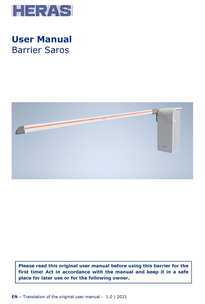
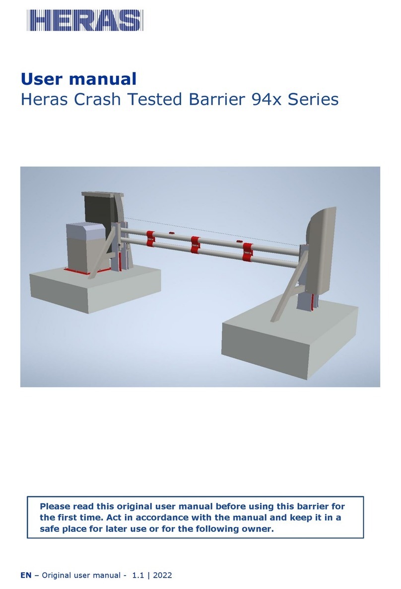
Heras 411 Series User manual

Series 411, 412 and 420
Hydraulic Vehicle Barrier
Installation Manual
Please read this manual before using this product for the rst time!
Act in accordance with the manual and keep it in a safe place for later use
or for the following owner.

EN | Original User Manual | 1.3
2

3
FOREWORD..................................................................................................... 4
1 SAFETY.................................................................................................. 5
1.1 EXPLANATION OF THE WARNINGS......................................................... 7
1.2 PERSONAL PROTECTIVE EQUIPMENT...................................................... 5
1.3 GENERAL SAFETY................................................................................ 5
1.4 LIFTING EQUIPMENT............................................................................ 6
2EQUIPMENT DETAILS............................................................................. 7
3 INSTALLATION ..................................................................................... 8
3.1 FOUNDATION DETAILS......................................................................... 8
3.2 BARRIERINSTALLATION....................................................................... 8
3.3 LID REMOVAL..................................................................................... 8
3.4 RECOMMENDED TOOLS........................................................................ 10
3.5 ELECTRICAL OPERATING SYSTEM......................................................... 10

EN | Original User Manual | 1.3
4
FOREWORD
This manual provides information on the installation of the barrier unit. A separate manual is
provide for operation and maintenance. Although every eort has been made to ensure that
the information contained in this manual is correct at the time of issue, no responsibility is
accepted for any loss or damage arising from incorrect information.
This manual forms no part whatsoever of any contract or agreement between Heras and
others. In no circumstances will Heras be responsible or liable for any costs, damage or injury
whatsoever arising from the use of this Manual.
Should the equipment be tampered with and/or any non-approved addons tted to the
equipment then any warranty will be considered void.
The Copyright of this Manual remains the property of Heras at all times. This Manual may not
be reproduced by any means without prior written permission from Heras.

EN | Original User Manual | 1.3
5
1 SAFETY
1.1 EXPLANATION OF WARNINGS
Warnings are used to highlight information safety critical information and to ensure the safe
installation of this equipment. Be sure to understand what each warning symbol indicates
before attempting installation.
• A situation that poses a severe and imminent danger to personnel
• A situation that poses a severe and imminent danger to personnel from electrical
equipment or a power supply
• A situation that poses a danger to personnel from a hazardous substance
• A general situation that poses a risk to personnel and or damage to equipment
• A situation where additional information is required
1.2 PERSONAL PROTECTIVE EQUIPMENT
Personal Protective Equipment (PPE) must be used where necessary. Heras recommend the
following PPE as minimum safety requirements.
• Safety glasses
• Hard hat
• Safety gloves
• Safety boots
• Ear defenders
• High visibility vest

EN | Original User Manual | 1.3
6
1.3 GENERAL SAFETY
Only persons trained in accordance with health and safety regulations should perform the
installation. The safety precautions that follow are not specic to the equipment under test.
Follow all local Health and Safety regulations and Safe Working Practices. When performing a
procedure the installation be sure to:
• Report any equipment defects that pose a danger to the safety, health and welfare.
• Wear all applicable Personal Protective Equipment (PPE).
• Avoid causing injury to you or other persons.
• Assess that all cranes and lifting equipment are serviceable and calibrated, and have the
correct Safe Working Load (SWL) for the task.
• Use only approved tools, recommended consumable materials.
• Isolate all applicable power sources (fuel/electrical/hydraulic/pneumatic), and ensure that
applicable WARNING signs are visible where necessary.
• Clear all work areas of unneeded tools, equipment and materials.
• Dispose of all unwanted consumable materials in accordance with local health and safety
and environmental regulations.
1.4 LIFTING EQUIPMENT
Before making use of any lifting equipment, be sure to:
• Examine the equipment for any signs of damage.
• Make sure the lifting equipment is suitable for the load.
• Make sure the slings are correctly placed and loading diameter is sucient.
• Mark the weight of the item to be lifted.
• Make sure the SWL of lifting equipment is not exceeded.
• Make sure the shackles can be double locked, e.g. nut and split pin if necessary.

EN | Original User Manual | 1.3
7
2 EQUIPMENT DETAILS
Description: Series 411 – 420 Hydraulic Vehicle Barrier
Controllers:
1 No Integrated Programmable Controller with
provision for connection of remote push button and
card access control.
Available
Additional
Equipment:
Skirts, Vehicle Loop Detectors, Photocells, Trac
Lights & Push Buttons/Keyswitches, Signs, Sounders,
Locks and Safety Edges
Electrical Supply:
Standard Models required a Single Phase
230VAC 50 Hz Supply rated @ 10 Amps.
Non- standard Three Phase Models (available at an
extra cost) require Three Phase & Neutral
400VAC 50 Hz Supply rated @ 6 Amps.
Cabinet Dimensions: 400 x 300 x 5mm
Cabinet Overall Height: 1150mm
Beam Section:
3” Circular Section
4” Circular Section
(dependent on barrier model)
Beam Centre Height: 1000 mm (approximate)
Operating Time: 8-15 Seconds
Standard Colour: BS 04E53 Poppy Red – Other RAL/BS colours
available on request.

EN | Original User Manual | 1.3
8
3 INSTALLATION
3.1 FOUNDATION DETAILS
Important note- the following details are typical only. Please refer to site-specic drawings,
which were issued with your order.
Barrier xings M16 x 135
Hilti Type HAS bolts
End support xings
M10x120 Hilti type HAS
bolt.
Ensure concrete
foundations are suitable
for secure xing of these
bolts
Bases must be perfectly
level in themselves, to
prevent the need for
excessive shimming of
equipment.
End support post if
supplied is telescopic.

EN | Original User Manual | 1.3
9
3.2 BARRIER INSTALLATION
• Before installation commences thoroughly check all base sizes and positions in accordance
with the issued drawings.
• Check the quantity, sizes and positions of all installed mains, control and loop cables
within the ducts.
• With beam removed, position barrier as shown on the drawings and check the supplied
beam length is equal or more than, that which is required.
• For guidance only and if an end support post is being used: -
• If Trief kerbs are installed, the beam should be at least 1124mm longer than the kerb-to-
kerb width.
• If standard kerbs are installed, the beam should be at least 604mm longer than the kerb-
to-kerb width.
• If there are no kerbs the beam length should be at least 364mm longer than the
foundation-to-foundation width.
• Fix the barrier in position using 1 M10 Hilti type bolt in the central xing position. Ensuring
that the cables are pulled through the rectangular 100 x 250 cut out in the barrier base
plate.
• Connect the mains supply into the isolator.
• Connect the control and loop cables (if installed.)
• Check the barrier raises and lowers correctly.
• Lower the barrier to horizontal. The mains must now be isolated using the isolator
switch within the barrier cabinet.
• Attach the barrier beam.
• Check the alignment of the beam across the entrance, ensuring that it lies central within
the end support post (if supplied).
• Fit the remaining 5 x M16 xing down bolts, ensuring that the barrier base is shimmed
level before the bolts are fully tightened.
• Commission the barrier.

EN | Original User Manual | 1.3
10
3.3 LID REMOVAL
In order to access the mechanical drive shaft and bearing assemblies, and to adjust the limit
switches, it will be necessary to remove the lid of the barrier. This is a simple operation but
should still be approached with care at all times.
In order to remove the lid the door must rst be opened using the keys supplied with the
barrier.
The barrier must now be immediately isolated from the mains electricity supply by turning o
the supply at the isolator as indicated in the drawing.
Underneath the top plate located centrally is a wing nut this must be removed from the
location rod, and carefully stored for later.
The lid can now be removed carefully from the barrier cabinet in an upward direction.
Important note- Ensure that the lid and all xings are safely stored so that damage or loss is
avoided. In severe weather ensure that the lid is removed for very short periods of time or
that the barrier is adequately protected.
Lid removed
vertically.
Remove wing nut
to allow lid to be
removed.
Sectional drawing showing lid xing stud wing nut location
With the lid removed extreme care should be taken if the barrier is operated with the
mains supply energised. Multiple trapping hazards exist. Any adjustments should only
be carried out by a suitably trained and qualied engineer.

EN | Original User Manual | 1.3
11
3.4 BEAM ATTACHMENT AND REMOVAL
The beam xing arrangement is shown in Fig 4 (below)
If the beam is being attached during installation, check the length of beam and shorten if
required. Carefully remove any burrs and t the supplied black plastic end cap into the cut
end of the beam.
Fig 4- Drawing showing beam xings
3.5 ELECTRICAL OPERATING SYSTEM
The electrical control panel is tted inside the barrier cabinet within an IP rated
enclosure.
All control electrical connections are pre-wired at our factory, only mains cable and
external control cables require connecting on site.
The position of the beam is detected in the raised and lowered positions by two limit switches
that are xed to the top plate of the barrier cabinet.
For safety reasons an isolator switch is tted on all barriers this should be turned o before
any work is carried out on the barrier.

Heras
33 Stakehill Industrial Estate
Middleton
Manchester
M24 2RW
United Kingdom
Local supplier stamp:
This manual suits for next models
2
Table of contents
Other Heras Control System manuals