ABB FEN-21 User manual
—
OPTIONS FOR ABB DRIVES AND CONVERTERS
Resolver Interface FEN-21
User's manual


Table of contents
1 Safety instructions
7Contents of this chapter ........................................................................
7Overview ............................................................................................
7General safety instructions .....................................................................
2 Introduction
9Contents of this chapter ........................................................................
9Intended audience ................................................................................
9Before you start ...................................................................................
3 Hardware description
11Contents of this chapter ........................................................................
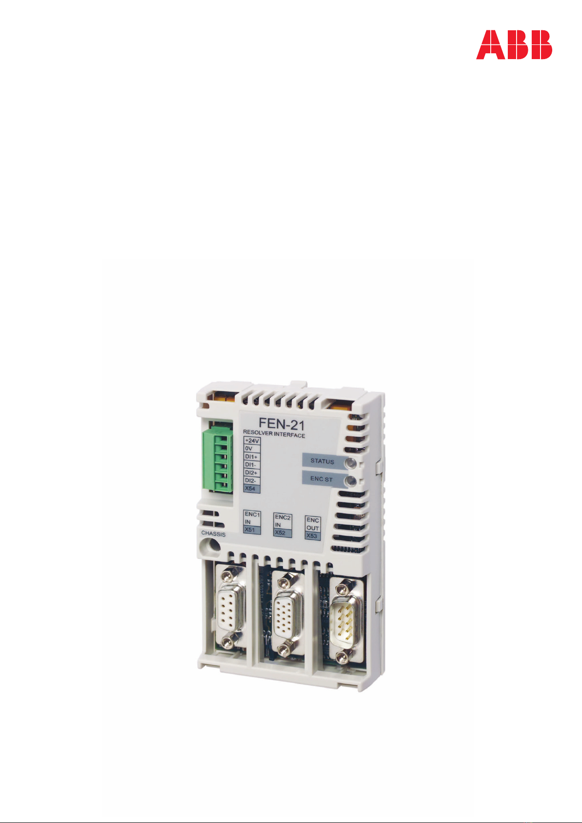
12The FEN-21 Resolver Interface .................................................................
13FEN-21 connections ...........................................................................
14Isolation areas .................................................................................
14Compatibility ......................................................................................
14Resolvers ........................................................................................
14TTL Encoders ..................................................................................
4 Installation
15Contents of this chapter ........................................................................
16Setting the supply voltage ......................................................................
17Mounting ...........................................................................................
17Terminal designations ...........................................................................
17Abbreviations ..................................................................................
18TTL encoder input (X51) .....................................................................
19Resolver input ..................................................................................
20TTL encoder emulation output (X53) .....................................................
20Digital inputs for position latching (X54) ................................................
21General encoder wiring guidelines ............................................................
22TTL Encoder input (X51) .....................................................................
23Resolver input (X52) ..........................................................................
25TTL Encoder emulation output (X53) .....................................................
26Digital inputs for position latching (X54) ................................................
27General encoder phasing principle ...........................................................
28Excitation signal ...............................................................................
5 Start-up
29Contents of this chapter ........................................................................
29Programming ......................................................................................
6 Fault tracing
31Contents of this chapter ........................................................................
31Diagnostic LEDs ..................................................................................
Table of contents 5

7 Technical data
33Contents of this chapter ........................................................................
34Dimensions ........................................................................................
34General ..............................................................................................
34Connectors .........................................................................................
35TTL encoder input (X51) .........................................................................
35Resolver interface ................................................................................
35TTL encoder emulation output (X53) .........................................................
35Digital inputs for position latch (X54) .......................................................
Further information
6 Table of contents

Safety instructions
Contents of this chapter
The chapter contains the warning symbols and the safety instructions which you must
obey when you install or connect an optional module to a drive or converter. If you
ignore the safety instructions, injury, death or damage can occur. Read this chapter
before you start the installation.
Overview
This chapter states the general safety instructions that must be followed when
installing and operating the FEN-21.
In addition to the safety instructions given below, read the complete safety instructions
of the specific drive you are working on.
These warnings are intended for all who work on the drive. Ignoring the instructions
can cause physical injury or death, or damage the equipment.
General safety instructions
WARNING!
All electrical installation and maintenance work on the drive must be carried
out by qualified electricians only.
The drive and adjoining equipment must be properly earthed.
Do not attempt any work on a powered drive. After switching off the mains, always
allow the intermediate circuit capacitors 5 minutes to discharge before working on
the frequency converter, the motor or the motor cable. Check (with a voltage tester)
that the drive is in fact discharged before beginning work.
1
Safety instructions 7

The motor cable terminals of the drive are at a dangerously high voltage when mains
power is applied, regardless of motor operation.
There can be dangerous voltages inside the drive from external control circuits even
when the drive mains power is shut off.
Exercise appropriate care when working on the unit.
These warnings are intended for all who work on the drive. Ignoring the instructions
can cause physical injury or death, or damage the equipment.
For complete safety instructions see the drive manuals.
8 Safety instructions

Introduction
Contents of this chapter
This chapter introduces this manual.
Intended audience
The manual is intended for the people who are responsible for commissioning and
using the FEN-21. The reader is expected to have a basic knowledge of electrical
fundamentals, electrical wiring practices and how to operate the drive.
Before you start
It is assumed that the drive is installed and the drive power supply is switched off
before starting the installation of the extension module. Ensure that all dangerous
voltages connected from external control circuits to the inputs and outputs of the
drive are switched off.
In addition to conventional installation tools, have the drive manuals available during
the installation as they contain important information not included in this manual.
The drive manuals are referred to at various points of this document.
2
Introduction 9

10
Other manuals for FEN-21
1
Table of contents
Other ABB Recording Equipment manuals


