HERKULES EnKon OFC7 User manual

1011194 (OFC7).xlsx
Herkules Equipment Corporation
2760 Ridgeway Court
Walled Lake, MI 48390-1662 USA
248-960-7100
800-444-4351
Fax 248 960-7109
Patents USA 7070167 4793369, 4960142, 5174317, 5193561, 5485860 Canada 1299468 & Patents Pending
website: www.herkules.us
Made in the USA
Made in USA
by
OWNERS MANUAL
This manual contains important information
concerning the
installation and operation of the equipment listed
below.
INSTRUCTIONS
Page 1 of 11

Warnings
……………………………………………………………………………………………………………….................. 3
Cautions …………………………………………………………………………………………………………………………. 3
Model Information ……………………………………………………………………………………………………………….. 4
Important Instructions ………………………………………………………………………………………………………...... 5
Installation ………………………………………………………………………………………………………………………… 6
Operation ……………………………………………………………………………………………………………………….... 7
Maintenance ……………………………………………………………………………………………………………….......... 8
Safety Tips ……………………………………………………………………………………………………………………........ 9
Bill of Material …………………………………………………………………………………………………………………... 10
Available Options …....................................................................................................................................................... 11
Limited Liability Warranty
The limited liability warranty applies to the pneumatic chambers of our Herkules crushers and to the initial user against
defected materials for a period of one year from the proof of purchase date. The limited liability warranty applies to other
components of our Herkules crushers to the initial user against defective materials for a period of one year from the proof of
purchase date.
This warranty does not apply to equipment damaged from accident, abuse, overload, misuse, negligence, improper
installation, abrasive or corrosive materials, or shipping damage.
In the event of failure, the defective item must be returned, freight prepaid, to the Herkules manufacturing plant for repair
or replacement. If repairs are required Herkules will not be liable for these repairs to take place in the field regardless
of the application. Proof of purchase and date of purchase must be confirmed. An RGA number (Return Goods
Authorization) and written approval from Herkules must be obtained before any goods can be shipped to Herkules.
We reserve the right to determine whether the cause of failure is due to defective material, normal wear, and/or other
causes.
There are no warranties which extend beyond the description on the face hereof. Herkules disclaims any
warranty of merchantability or fitness for a particular purpose in connection with the Buyer’s purchase
of any Product under this agreement. Damages are limited to the sales price of the Herkules system.
The terms and conditions herein represent the entire agreement between Herkules and the Buyer.
Any prior / future representations do not apply.
Table of Contents
Warning Symbol
Caution Symbol
CAUTION
WARNING
This symbol alerts you to the possibility of serious
injury or death if you do not follow the
instructions.
This symbol alerts you to the possibility of damage to or
destruction of equipment if you do not follow the
instructions.
Page 2 of 11

Warning:
This symbol alerts you to the possibility of serious injury or death if you do not follow
the instructions
Caution:
This symbol alerts you to the possibility of damage to or destruction of equipment if
you do not follow the instructions.
1. Herkules will not be held responsible for any personal injury and/or property damaged caused
due to owner/operator failure to follow the warnings and cautions listed in this manual.
2. Read and understand all warnings, cautions and instructions before operating this equipment.
3. It is the owner/operators responsibility to maintain the legibility of all warning and instruction labels.
4. Do not alter or modify any part of this equipment.
5. DO NOT open the door while the unit is operating. Always wait for the crusher to cycle completely.
6.
7. Always wear safety glasses when operating the crusher.
8. Always wear suitable industrial gloves when handling crushed objects to prevent injury.
9.
Prior to performing any maintenance on this crusher, the plunger MUST BE in the DOWN position with all air
pressure released from the system!
10. Check equipment regularly for proper operation and repair or replace worn or damaged parts immediately.
11. Any crusher that appears to be damaged in any way, is badly worn or operates abnormally shall be removed
from use until repairs are made. Use only manufacture's approved accessories and service parts.
Contact a factory authorized service center for repairs.
FAILURE TO HEED THE FOLLOWING WARNING MAY RESULT
IN PERSONAL INJURY AND/OR PROPERTY DAMAGE.
Crush only intended matter for the crusher.
Page 3 of 11

Maximum crushing pressure 35,000 Ibs.
Filter capacity One heavy duty filter
or four auto filters
Filter type Heavy duty
Filter crush Up to 80%
Residual oil removed from crushed filter 95 - 98%
Time to crush filter 35 - 55 seconds
Overall width 28-5/16"
Overall height 60-7/8"
Overall depth 27-5/8"
Chamber width 9-1/2"
Chamber height 14-3/4"
Chamber depth 9-1/2"
Required air pressure 70 p.s.i.
Required air flow 44 cfm
Total weight 575 Ibs.
Filter Specifications:
8" maximum filter diameter (single)
12" maximum height
Model OFC7 crusher is capable of crushing four filters at one time or one large heavy duty oil filter. The crusher is
designed for automotive and light truck shops to crush and dispose of used oil filters in an environmentally correct
manner. The crusher provides the following features:
1. Powerful 17.5 ton air bag crushing technology assures the force necessary to
do the job when crushing four filters.
2. Operates with external air only. No electric power is required.
3. Safe locked door protects operator.
4. Removes 95-98% of residual oil from oil filter.
5. Easy collection for oil drain off.
6. Four oil filter capacity.
Model Information
SPECIFICATIONS
Page 4 of 11

1. Read this manual thoroughly before installing, operating, or maintaining this crusher.
2. Following the installation of this crusher, this manual is to be delivered to the owner / user / employer of the crusher.
3. Read the anchor bolt instruction page before drilling and installing the anchor bolts.
4. The troubleshooting and maintenance procedures described in this manual can be done by the crusher’s owner /
employer. Any other procedure should be done only by trained crusher service personnel.
5. Herkules will not be held responsible for any personal injury and/or property damage due to
owner/operator failure to follow the warnings and cautions listed in this manual.
6. Do not operate crusher with defective Control assembly.
IMPORTANT INSTRUCTIONS
CAUTION
Page 5 of 11

Read this manual thoroughly before installing, operating, or maintaining this crusher.
DO NOT attempt to operate the unit while on a skid. The initial crush of the oil filter(s) will cause
the unit to move or jump if not secured properly. The crusher must be anchored to the floor before operating.
1. Determine where the crusher is to be installed. Make sure there is enough room in front,
and on the sides of the crusher.
2.
The back of the crusher must be placed against a wall for safety in the event of an air bag failure.
3. Anchor the unit to the floor using 1/2" diameter hardware.
4. Connect external air supply to the unit.
5. Place a waste oil collection receptacle underneath the unit centered about the drip pan hole.
OWNER/OPERATOR RESPONSIBILITY
It is the owner/operator responsibility to properly use and maintain this equipment.
The instructions and warnings contained in this manual shall be read and understood by the owner/operator prior
to operating this equipment.
If an owner/operator does not understand English, the contents of this manual shall be explained in the owner/
operator native language to assure the owner/operator comprehends.
It is the owner/operator responsibility to maintain the legibility of all warning and Instruction labels.
The owner/operator shall retain this manual for future reference to Important warnings, operating and maintenance
instructions.
50 weeks / year
35,000 cycles / year
INSTALLATION
TYPICAL DUTY CYCLE
3 shifts / day
8 hours / shift
7 days / week
100 cycles / day
Page 6 of 11

1. Connect the external air supply.
2. Lift the door latch and pull the door down to gain access to the crushing chamber.
3. Place the oil filter(s) to be crushed gasket side down on the bottom of the crushing chamber. Arrange the filters as
follows:
Quantity & Type Position
(1) Heavy duty filter Center of ram plate
(1) Auto filter Center of ram plate
(2) Auto filters Opposite corners
(3) Auto filters (2) in back corners and (1) in front center
(4) Auto filters (2) in back corners and (2) in front corners
4. Close the door and pull the door latch down securely.
5. Places the hand valve lever in the UP position.
6. Wait until the yellow indicator rod stops.
7. Place the hand valve lever in the DOWN position.
8. Wait until the yellow indicator rod stops.
9. Lift door latch and open door.
10. Remove the crushed oil filter and dispose of it in an environmentally correct manner.
OPERATION
WARNING
WARNING
The crushing mandrel may be still moving when
the door is opened. Wait until the mandrel stops
before placing hand in chamber.
A crushed oil filter may have jagged metal edges.
Use good industrial work gloves to protect the
hands when removing a crushed oil filter.
Page 7 of 11

1. Prior to performing any maintenance on this crusher, the plunger MUST BE in the DOWN position with all air
pressure released from the system!
2. Remove air line from crusher - ONLY when step #1 has been completed!
3. Regularly check the waste oil drain to prevent oil backing up in the crusher cabinet and causing an oil spill.
Clean, repair as required.
4. Regularly clean the crusher chamber to remove any accumulated oil sludge, metal particles or any other debris that
could affect the crusher operation or block the waste oil drain system.
5. Apply grease to door hinges on a regular basis to prevent the door from binding.
6. Apply motor oil to door latch pivot points on a regular basis to prevent latch from binding.
7. Unscrew crusher from floor and pull away from the wall to gain access to the back of he crusher when needed.
MAINTENANCE
Page 8 of 11

Read all instructions.
INSPECT your crusher daily. Never operate if it malfunctions or if is has broken or
damaged parts. Repairs should be made with original equipment parts.
Operating controls are designed to close when released. Do not block open or override them.
NEVER overload your crusher.
ONLY trained and authorized personnel should do operation of this crusher.
ALWAYS keep crusher area free of obstructions, grease, oil, trash and other debris.
ALWAYS WEAR SAFETY GLASSES. Everyday eyeglasses only have impact
resistance lenses; they are not safety glasses.
To reduce the risk of fire, do not operate equipment in the vicinity of open
containers of flammable liquids (gasoline).
Use only as described in this manual. Use only manufacturer’s recommended attachments.
ALWAYS DRAIN ALL AIR PRIOR TO ANY MAINTENANCE OF THIS CRUSHER.
POST THESE SAFETY TIPS WHERE THEY WILL BE A CONSTANT REMINDER TO
YOUR CRUSHER OPERATOR. FOR INFORMATION SPECIFIC TO THE CRUSHER, ALWAYS
REFER TO THE CRUSHER MANUFACTURER’S MANUAL.
It is the owner/operators responsibility to maintain the legibility of all warning and instruction labels.
DO NOT alter or modify any part of this equipment.
DO NOT operate crusher while person(s) are on the unit.
Recommended to anchor this crusher to the ground with (4) 3/4" lag bolts.
ALWAYS check equipment regularly for proper operation and repair or replace worn or damaged parts immediately.
ALWAYS remove damaged crushers from service until repairs are made to the unit. Use only manufacturer's
approved parts and accessories.
DO NOT REMOVE LABELS. REPLACE IF DAMAGED.
SAFETY TIPS
WARNING
Page 9 of 11

No. Quantity Units
83E BOLT HEX 1/2-13 X 3/4 GD 5 Z 1 EA
83F BOLT HEX 1/2-13 X 1 GD 5 Z 2 EA
84L NUT NYLOCK 5/16-18 Z 4 EA
85B 1EA
85D WASHER FLAT 1/2 SAE MIN TH .110 Z 2 EA
85H WASHER LOCK 1/2 Z 2 EA
M6A ELBOW 3/8 NPT 1 EA
12086 VALVE ASSY HAND LIFT VM 1 EA
18469 VAVLE P3 POS2 2 WAY ASSY 1 EA
18738 AIRBAG WELDMENT DBL 8 BAR 1 EA
18768 CRUSHER FRAME WELDMENT 27.7 X 27.8 X 60 1 EA
18769 PISTON WELDMENT 9 X 9 X 9.31 X 20.5 1 EA
18771
HANDLE WELDMENT FOR CRUSHER
1EA
18773 SPACER WELDMENT 15 OD X 5.62 ID X 1.0 1 EA
1000315 ELBOW 1/2 NPTF Z 1 EA
1001229 NUT HEX 3/4-10 PLAIN 1 EA
1001902 DECAL HERKULES WHITE 2.68 X 12.88 1 EA
1001941 WASHER FLAT 3/4 SAE Z 2 EA
1002404 STICKER WARNING INSTRUCTIONS 1 EA
1002644 BULKHEAD FITTING 1 EA
1003120 HOSE BARB PTL 1/2 X 3/8 NPT 1 EA
1003586 HOSE BARB PTL 1/2 X 1/2 NPT 1 EA
1005500 NIPPLE 1/2 NPT X 1-1/2 BRASS 1 EA
1007672 STICKER WARNING DON’T CRUSH AEROSOL/GAS CONT. 1EA
1007685 STICKER WARNING HAND CRUSH 1 EA
1009592 BOLT HEX 3/4-10 X 10 GD 5 Z 1 EA
1009596 BACK COVER 26.87 X 31.68 X 18 GA 1 EA
1009980 VINYL AIRBAG COVER 1 EA
1009981 INDICATOR ROD 1/2 OD X 19.50" 1 EA
1009987
SQUARE U-BOLT 5/16-18 X 2 X 3
2EA
1009988 SCREW BHSC 8-32 X 6 BLACK 2 EA
1010009 ROUND PLUG 5" DIAMETER 1 EA
1010010 ROUND PLUG 3/4" DIAMETER 1 EA
1010214 STICKER CRUSHER UP-DOWN 2 X 4 (LAM) 1 EA
1010217 STICKER CRUSHER DECAL 4.25 X 5.25 (LAM) 1 EA
1010392 STICKER WARNING INSTRUCTIONS 3.63 X 6.25 (LAM) 1 EA
008-112 BOLT HEX 5/8-11 X 1-1/4 Z 1 EA
008-353 CHAIN 1.5 X .19 GALV 16 IN
008-384
ANCHOR DOUBLE 1/2-13 X 2-1/2
4EA
008-385 BOLT HEX 1/2-13 X 2-1/2 GD Z 4 EA
009-124 WASHER FLAT 5/8 SAE Z 1 EA
100-332 HOSE 1/2" 16 IN
100-332 HOSE 1/2" 13 IN
100-332 HOSE 1/2" 29 IN
Bill of Materials
Description
WASHER 1-1/2 X 1 NYLON
Page 10 of 11
DET# PART# DESCRIPTION
Qty. Per
Assembly
Qty. Per
Crusher
UNITS
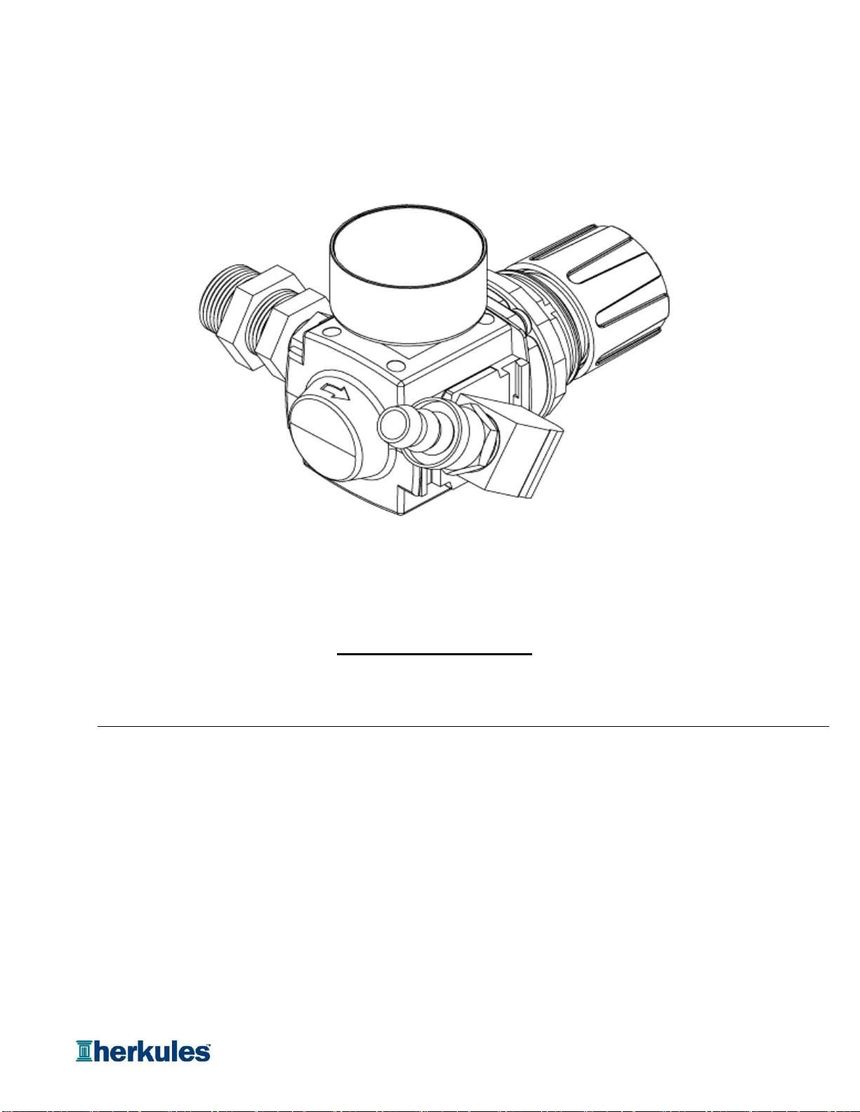
119945 REGULATOR KIT 1 1 EA
Assy
Includes:
18828 REGULATOR 1 1 EA
1003586 HOSE BARB 1/2 X 1/2NPT 1 1 EA
OFC7 AVAILABLE OPTIONS
Regulator Kit #19945
Page 11 of 11
Table of contents
Other HERKULES Industrial Equipment manuals


Popular Industrial Equipment manuals by other brands

Thermo Scientific
Thermo Scientific CTS Xenon installation guide

ABB
ABB HT571884 Operation manual

Parker
Parker OLAER HY10-4005-UM/UK Product information

SCHUNK
SCHUNK KGG 80 Assembly and operating manual

DTS
DTS SLICE Free Motion Headform user manual

Lippert Components
Lippert Components SOLIDSTEP 2.0 Master Owner's Manual


Larson Electronics
Larson Electronics Megatower RNT-WCDE-11-PLM50-6X500LTL-LED Operation manual

Challenge
Challenge iJOG Instructions and parts manual

HEIDENHAIN
HEIDENHAIN ND 2100 G GAGE-CHEK installation instructions

CHART
CHART Trifecta Pro 30K product manual

Nederman
Nederman FX2 Original Series user manual

Hoffmann
Hoffmann 10585 user manual