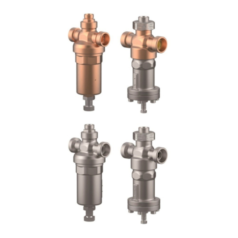
HEROSE 4186 Series User manual

herose.com
HEROSE GMBH ARMATUREN UND METALLE
Original
Operating and Installation Instructions
Combi-Regulator 4186
E
N

Operating and Installation Instructions
herose.com
Page 1
Operating and Installation Instructions
Combi-Regulator
Type 4186-1 and Type 4186-3
IMPORTANT:
PLEASE READ CAREFULLY BEFORE USE
KEEP FOR FUTURE REFERENCE
HEROSE GMBH
ARMATUREN UND METALLE
Elly-Heuss-Knapp-Straße 12
23843 Bad Oldesloe
Tel: 04531 509-0
Fax: 04531 509-120
Web: http://www.herose.com
5th edition 07/2016
© HEROSE 2015
Disclosure and reproduction of this document as well as utilisation and communication
of its content are prohibited unless explicitly permitted Infringements will attract claims
for compensation. All rights for registration of patents or design reserved.

Operating and Installation Instructions
herose.com
Page 2
Contents
1. Schematic Illustration of Combi-Regulator.............................................................4
1.1. Illustration 4186-1..............................................................................................4
1.2. Illustration 4186-3..............................................................................................5
2. General information About These Operating Instructions......................................6
3. Safety ....................................................................................................................6
3.1. Symbols and Signal Words ...............................................................................6
3.2. Safety Related Definitions.................................................................................7
3.3. Basic Safety Information ...................................................................................7
3.4. Qualified Personnel...........................................................................................8
4. Transport and Storage...........................................................................................8
4.1. Transport...........................................................................................................8
4.2. Storage..............................................................................................................8
5. Technical Data.......................................................................................................8
5.1. Purpose and Field of Use..................................................................................8
5.2. Function ............................................................................................................9
5.2.1. Pressure Build-up Function...........................................................................9
5.2.2. Pressure Build-up/Economizer Function.......................................................9
5.2.3. Safety Function.............................................................................................9
5.3. Product Data .....................................................................................................9
5.3.1. Operating Data 4186-1 ...............................................................................10
5.3.2. Operating Data 4186-3 ...............................................................................10
5.3.3. Technical Data 4186-1................................................................................10
5.3.4. Technical Data 4186-3................................................................................10
6. Installation ...........................................................................................................10
6.1. Handling Prior to Installation of the Regulator.................................................10
6.2. Information of Hazards During Installation, Operation and Maintenance ........10
6.3. Basic Installation Notes...................................................................................11
6.4. General Installation Notes...............................................................................11
6.5. Product-specific Installation Position and Installation Notes............................12

Operating and Installation Instructions
herose.com
Page 3
7. Operation and Maintenance ................................................................................12
7.1. Commissioning................................................................................................12
7.2. Adjusting the Nominal Working Pressure........................................................12
7.3. Maintenance and Repair of the Valve .............................................................14
7.4. Dismantling the Valve......................................................................................14
8. Other Applicable Documents...............................................................................15
9. Warranty..............................................................................................................15
10. EU Declaration of Conformity..................... Fehler! Textmarke nicht definiert.
11. Notes...............................................................................................................17

Operating and Installation Instructions
herose.com
Page 4
1. Schematic Illustration of Combi-Regulator
1.1. Illustration 4186-1
A
B
C
Einstellschraube SW 27
Kontermutter SW 30
Ø
Locknut SW 30
Set point screw SW 27

Operating and Installation Instructions
herose.com
Page 5
1.2. Illustration 4186-3
Locknut SW 19
Set point screw SW 14

Operating and Installation Instructions
herose.com
Page 6
2. General information About These Operating Instructions
These Operating Instructions contain the instructions for the safe installation and
operation of the valve in the proper manner. If difficulties occur, which cannot be
resolved with the aid of these Operating Instructions, please contact HEROSE
GMBH ARMATUREN UND METALLE for further information.
These Operating Instructions comply with the relevant currently valid EU safety
standards as well as the currently valid rules and regulations of the Federal
Republic of Germany. For use of the valve outside of the Federal Republic of
Germany, the operator, or the company responsible for the design of the system
must ensure that the current national regulations are complied with. HEROSE
GMBH reserves the right to make technical modifications and improvements at
any time. The use of these Operating Instructions assumes that the user is
qualified as described under section 2.4 "Qualified personnel". The operating
personnel must be instructed according to these Operating Instructions.
Certain rules and regulations apply according to the system and the medium.
These rules and regulations must be observed. In addition to the information in
these Operating and Installation Instructions, the general Industrial Health and
Safety regulations must be observed. Environmental regulations must also be
observed.
3. Safety
3.1. Symbols and Signal Words
Symbol / Signal Word
Significance
Indicates the use and effect of safety information.
Indicates possible material damage and other important
information.
Indicates a hazardous situation which may cause slight to
moderate injuries if it is not avoided.
Indicates a hazardous situation which may cause serious
injuries or death if it is not avoided.
Indicates a hazardous situation which will cause serious
injuries or death if it is not avoided.

Operating and Installation Instructions
herose.com
Page 7
3.2. Safety Related Definitions
The signal definitions DANGER, WARNING, WARNING and NOTE are used in
these Operating Instructions for information with regard to special hazards or for
extraordinary information which requires special labelling.
However, observation of the other transport, installation, operation and
maintenance information which is not specially emphasised, as well as the
technical data (in the Operating Instructions, the product documentation and on
the device itself) is equally important in order to prevent faults, which in turn may
directly or indirectly cause injury or damage.
3.3. Basic Safety Information
The safety and warning information is structured as follows:
Source of hazard
Results if the hazard is ignored.
Measures to prevent the hazard and avoid injuries.
Hazardous Media
Poisoning, caustic burns, burns, injuries.
Use suitable protective equipment
Use suitable collection containers
Wear suitable protective equipment
Foreign Bodies in the Regulator
Hazards due to failure or leaking regulator
Flush the system before installation.
Check the regulator for foreign bodies
Remove foreign bodies.
Residual Medium in the Regulator
Poisoning, caustic burns, burns, injuries.
Wear suitable protective equipment
Remove residual medium.
Leaking Regulator
Hazard due to media escaping because of damaged seals or sealing surfaces.
Protect the regulator from shocks and impacts, especially during
transport and installation.
Regularly check the regulator for leaks.

Operating and Installation Instructions
herose.com
Page 8
Hot Medium
Burns or scalds.
Wear suitable protective equipment
Hot Surfaces
Burns
Wear suitable protective equipment
Aggressive Medium
Caustic burns
Wear suitable protective equipment
3.4. Qualified Personnel
These are persons who are familiar with the installation, assembly, commissioning
and operation of the product and are properly qualified for their work and
functions. This includes, e.g. instruction and obligation to compliance with all
regional and company regulations and requirements for use, training or instruction
according to safety standards, with regard to the care for and use of proper safety
and industrial protective equipment, training in first-aid etc. (see also BetrSichV
[German Health and Safety Regulations] and its TRBS [Technical Rules for
Operating Safety]).
4. Transport and Storage
4.1. Transport
- Transport temperature: - 20°C to + 65°C
- - Protect against external effects (shock, impact, vibration and dirt)
4.2. Storage
- Storage temperature - 20°C to 65°C, dry and free from dirt
- In damp areas: Desiccant or heating is necessary to prevent the formation of
condensation.
5. Technical Data
5.1. Purpose and Field of Use
The HEROSE Combi-Regulator is used for automatic pressure regulation in fixed
tanks for liquid and cryogenic technical gases. Without auxiliary energy, the
Combi-Regulator ensures that in spite of temperature fluctuations, a constant, pre-
defined specified pressure is maintained in the tank during the entire period of
operation.
In addition to the pressure build-up function and the pressure
reduction/economizer function, the Combi-Regulator is equipped with a safety
function which protects the inlet piping and its components.

Operating and Installation Instructions
herose.com
Page 9
The field of use of the Combi-Regulator - under largely constant pressure
conditions - is the responsibility of the system planner. Special labelling of the
valve must be observed.
- Permitted operating media: Oxygen, nitrogen, argon, krypton, carbon dioxide,
nitrous oxide, chlorotrifluoromethane, trifluoromethane, carbon monoxide,
methane, ethane and ethylene
-Valves for use with oxygen are permanently marked with “O2”.
-Observe the max. P/T 30bar/60°C
It is essential to consult HEROSE in case of use with media which
require or exclude particular materials.
Compatibility between the medium and the housing or sealing
material is the responsibility of the operator.
5.2. Function
5.2.1. Pressure Build-up Function
If the pressure in the vessel is less than the nominal working pressure which is set,
the Combi-Regulator opens in order to restore the nominal working pressure.
Flow direction AB
5.2.2. Pressure Build-up/Economizer Function
If the pressure in the vessel exceeds the nominal working pressure by 0.5 bare,
the economizer function of the Combi-Regulator responds in order restore the
nominal working pressure.
Flow direction BC
5.2.3. Safety Function
If the pressure in the inlet line (upstream of connection A) exceeds the nominal
working pressure of the vessel by 5bar +10% (max. 5,5bar), the safety function
triggers and reduces the pressure in the corresponding section of the piping.
Flow direction AB+C
5.3. Product Data
The principle dimensions of the HEROSE Combi-Regulator can be obtained from the
illustrations on page 4 and page 5 of the Operating Instructions.

Operating and Installation Instructions
herose.com
Page 10
5.3.1. Operating Data
4186-1
5.3.2. Operating Data
4186-3
Nominal pressure:
PN50
PN40
Operating
temperatures
Medium
-196°C to +200°C
Ambient temperature
-40°C to +65°C
Max. working pressure
38bar
Care must be taken that the Combi-Regulator is only used in areas
where the temperatures, media and operating pressures stated in these
Operating Instructions are complied with.
5.3.3. Technical Data
4186-1
5.3.4. Technical Data
4186-3
KVS-/CV- Value
KVS=1.2 m³/h /
CV=1.4 gal/min
KVS=3.2 m³/h /
CV=3.7 gal/min
Safety function
Response pressure
5.0bar+10% (max.5.5bar) above working
pressure
Economizer function
Response pressure:
0.5 bar above working pressure
Working pressure
ranges
1-12bar
6-24bar
16-38bar
2-10bar
8-22bar
20-38bar
6. Installation
6.1. Handling Prior to Installation of the Regulator
If the valves are provided with protective caps, these must only be removed
immediately prior to installation.
Protect from dirt and weather, e.g. dampness.
Correct handling prevents damage!
The valves are free of oil and grease for use with oxygen. Only open the
packaging for use.
Clean all tools before starting work. Make sure they are free of oil and
grease.
6.2. Information of Hazards During Installation, Operation and Maintenance
Safe operation of the valve is only ensured if it is installed, commissioned and
maintained by qualified personnel (see Section 3.4 "Qualified personnel") in
accordance with the warning information in these Operating Instructions.

Operating and Installation Instructions
herose.com
Page 11
A
B
C
Top
Bottom
Set point screw
Locknut
In addition, compliance with the general installation and safety regulations for pipe
or plant construction, as well as the proper use of tools and protective equipment
must be ensured. It is essential that the Operating Instructions for the valve or the
instructions for using the valve are observed for all work. Failure to comply with
this may result in injury or material damage.
If sealing tape or liquid sealants are used, there is a danger that parts of
these may enter into the valve and impair its function or seal.
Avoid damage during installation!
Set the tightening torque so that damage to the connections is avoided.
Only use suitable tools, such as open-ended or ring spanners (ensure
suitability for O2)
6.3. Basic Installation Notes
Tension free installation must be ensured
The valve must not serve as a fixed point, it is supported by the piping
system,
The connecting piping must be connected without force or torsion.
Valves must be protected against dirt, especially during construction work
: Free from oil and grease for use with O2,
Expansion of the piping due to heat must be compensated by the use of
compensators,
Do not paint!
6.4. General Installation Notes
In addition to the basic installation
regulations, the following points must be
taken into account:
Visual examination of the labelling
(see 5.3) with regard to the conditions
of use and operating pressure
Visual examination for external
damage. Do not install damaged
valves.
Remove protective caps or covers if
present.
The space inside the valve and the
pressure vessel must be free of foreign
bodies.
At low or high surface temperatures,
appropriate protection must be
provided or the operating personnel
must be informed.
Figure 1: Installation position

Operating and Installation Instructions
herose.com
Page 12
6.5. Product-specific Installation Position and Installation Notes
The HEROSE Combi-Regulator must be installed in the system according to the
flow direction (AB) with the major axis –in which the two connections A and B
are located –in a horizontal installation position without tension. During and after
installation, connection C must point vertically upward.
The set point screw for the working pressure points vertically downwards. (see
Figure 1) This installation position applies to both the Combi-Regulator 4186-1 and
the Combi-Regulator 4186-3. The illustration is purely schematic.
The Combi-Regulator must be installed in the system so that it is easily
accessible, e.g. for maintenance and changes to the nominal working pressure.
The system planner must design the plant system for at least the working pressure
plus the response pressure of the safety function.
7. Operation and Maintenance
7.1. Commissioning
Prior to commissioning, the details of the material, pressure, temperature and
installation position must be checked against the plan of the piping system.
The BetrSichV [German Health and Safety Regulations] and its TRBS
[Technical Rules for Operating Safety] must be observed,
Residues in the piping and valve (dirt, welding beads, etc.) will inevitably
result in leaks.
The following must be ensured before each commissioning of a new system or the
recommissioning of a system after repairs or conversion work:
Correct completion of all installation and assembly work,
Commissioning must only be carried out be "Qualified personnel" (see
Section 3.4)
The correct functional position of the valve must be ensured and
Existing guards must be installed or repaired.
7.2. Adjusting the Nominal Working Pressure
On delivery, the Combi-Regulator is set to a pre-defined working pressure.
Depending on the delivered working pressure range, the Combi-Regulator is set
accordingly. At the request of the customer, the Combi-Regulator can be pre-set to
a specific working pressure.
Working pressure range
Combi-Regulator
4186-1
Combi-Regulator
4186-3
1-12bar
6-24bar
16-38bar
2-10bar
8-22bar
20-38bar
Pre-set nominal working
pressure
8bar
12bar
20bar
8bar
12bar
20bar
Nominal working
pressure change per
rotation
1.3bar
2bar
3bar
0.8bar
1.7bar
2.7bar
Table 1: Nominal working pressure

Operating and Installation Instructions
herose.com
Page 13
0
5
10
15
20
25
30
35
40
0 1 2 3 4 5 6 7 8 9 10 11 12
Nominal working pressure [bar]
Rotations of set point screw
Adjustment diagram: Nominal working
pressure
Combi-Regulator 4186-3
20-
8-
2-
To set or correct a nominal working pressure, adjust the set point screw of the
Combi-Regulator:
Clockwise rotation
The nominal working pressure is increased
Counter-clockwise rotation
The nominal working pressure is reduced
The value for the change to the nominal working pressure per rotation of the screw
must be obtained either from Table 1 or Adjustment diagram 1.
If pressure gauges are used in the system it is recommended that the
Combi-Regulator is adjusted according to the values indicated on the pressure
gauge. If the system does not provide this facility adjustment of the nominal
working pressure can be carried out on the basis of Adjustment diagram 1.
To adjust the nominal working pressure, loosen the lock nut and adjust the set
point screw accordingly. Once the required nominal-working pressure has been
set, the set point screw must be secured again with the lock nut.
0
5
10
15
20
25
30
35
40
0 1 2 3 4 5 6 7 8 9 10 11 12
Nominal working pressure [bar]
Rotations of set point screw
Adjustment diagram: Nominal working
pressure
Combi-Regulator 4186-1
16-
6-
1-
Adjustment diagram 1: Nominal working pressure

Operating and Installation Instructions
herose.com
Page 14
7.3. Maintenance and Repair of the Valve
The maintenance and maintenance intervals must be specified by the operator
according to the conditions of use, see BetrSichV [German Health and Safety
Regulations] and the associated TRBS [Technical Rules for Operating Safety]
Series 1000 and 2000.
All maintenance, repair and commissioning work must only be carried out by
qualified personnel who are familiar with the installation, commissioning and
operation of the product.
Hazards may be caused by the operating pressure during maintenance or
dismantling. The section of the system must be depressurised. The Combi-
Regulator must be removed from the piping for maintenance.
During (external) cleaning, take care that no chemical agents are used which
affect the properties of the materials. During cleaning, take care that the
adjustment of the set point screw is not changed and that the lock nut is firmly
screwed against the spring cover.
During repairs, maintenance and cleaning, the condensation drain hole in the
spring cover must be visually inspected regularly and any dirt must be removed.
Repairs may only be performed by HEROSE or by specialist workshops
authorised by HEROSE, with the exclusive use of original spare parts. The contact
details for workshops authorised by HEROSE can be found on the HEROSE
homepage (http://www.herose.com).
7.4. Dismantling the Valve
In addition to the generally valid installation guidelines and the BetrSichV [German
Health and Safety Regulations] and its TRBS [Technical Rules for Operating
Safety] Series 1000 and 2000, the following points must be observed:
The piping system must be depressurised
The medium and the valve must be cooled to the ambient temperature
The system must be drained
Purge the piping system in case of aggressive or caustic media
Installation must only be performed by "Qualified personnel" (see Section
3.4)
Escaping Medium
Hazard to humans and the environment
Take safety precautions appropriate to the medium
Collect the medium from the piping system
Do not allow unauthorised persons into the danger area.
Wear suitable protective equipment

Operating and Installation Instructions
herose.com
Page 15
8. Other Applicable Documents
Pressure equipment directive 2014/68/EU
For installation in Germany
Druckgeräteverordnung (14.ProdSV) [Pressure Equipment Regulation]
Betriebssicherheitsverordnung (BetrSichV) [German Health and Safety
Regulations]
Technical Rules for Operating Safety (TRBS)
Other EU Countries
Relevant national regulations
9. Warranty
The scope and period of warranty is stated in the current version of the "General
Terms and Conditions of Business of HEROSE GMBH" which is valid at the time
of delivery, or in deviation from these, in the purchase contract. No warranty can
be accepted for damage which is due to incorrect handling or failure to observe
these Operating and Installation Instructions, regulations by the employers' liability
insurance associations for industrial health and safety, or EN, DIN, VDE standards
and other rules.
Damage which occurs during operation due to conditions of use which deviate
from the conditions of use specified in the data sheet or in other agreements are
also not subject to warranty. Claims which exceed those covered by the warranty
are excluded. There is no entitlement to the supply of replacements. Maintenance
work, installation of third party components, modifications to the construction as
well as natural wear and tear are excluded from the warranty. Any transport
damage should not be reported to us, but rather to the responsible goods handling
department of the railway or carrier, as otherwise claims for compensation against
these companies may become invalid.

Operating and Installation Instructions
herose.com
Page 16

Operating and Installation Instructions
herose.com
Page 17
10. Notes
This manual suits for next models
2
Table of contents
Other HEROSE Controllers manuals
Popular Controllers manuals by other brands

ABB
ABB ACQ80 Firmware manual

Extron electronics
Extron electronics MediaLink Controllers with IP Link MLC 104 IP... Specification sheet

Lumens
Lumens VS-KB30 Firmware upgrade
Syntec instruments
Syntec instruments 6A Series Hardware specifications

Motoman
Motoman NX100 Function manual

roco
roco MultiMAUS manual
