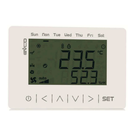
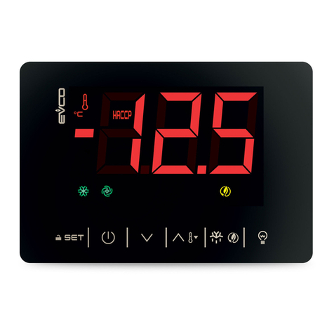
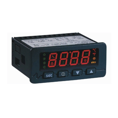
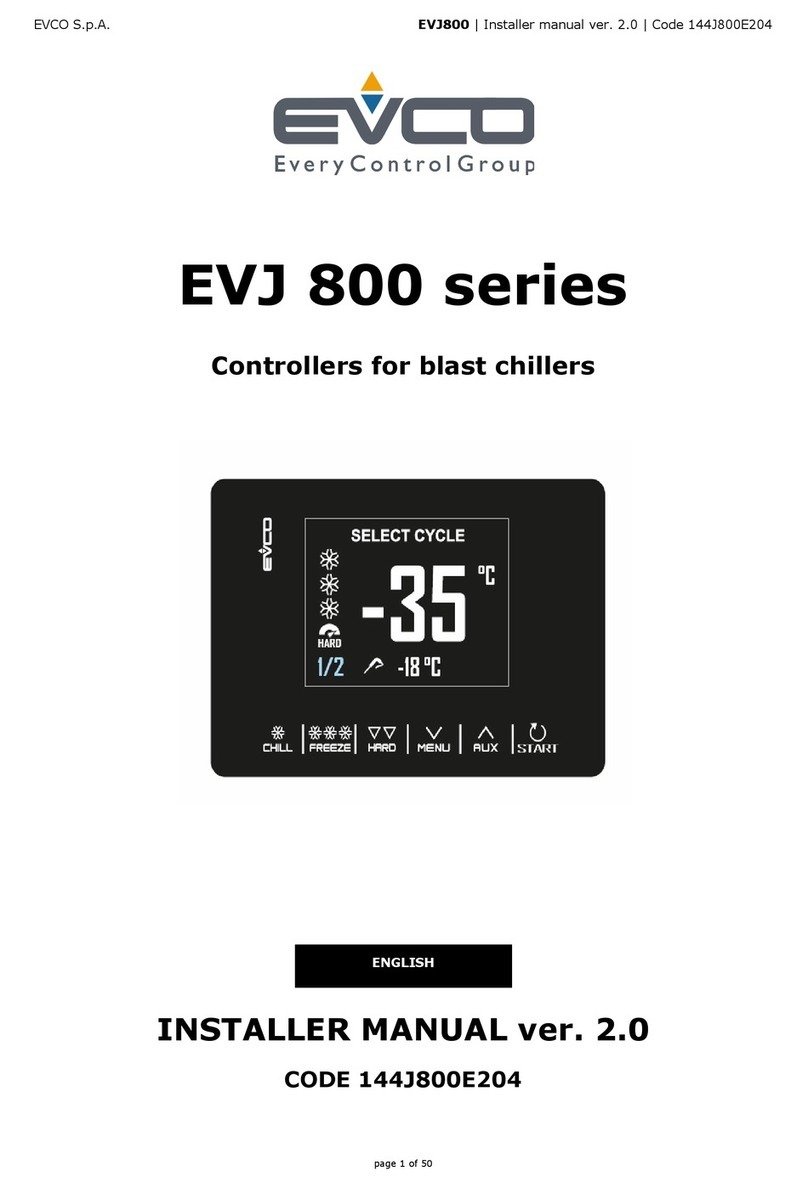
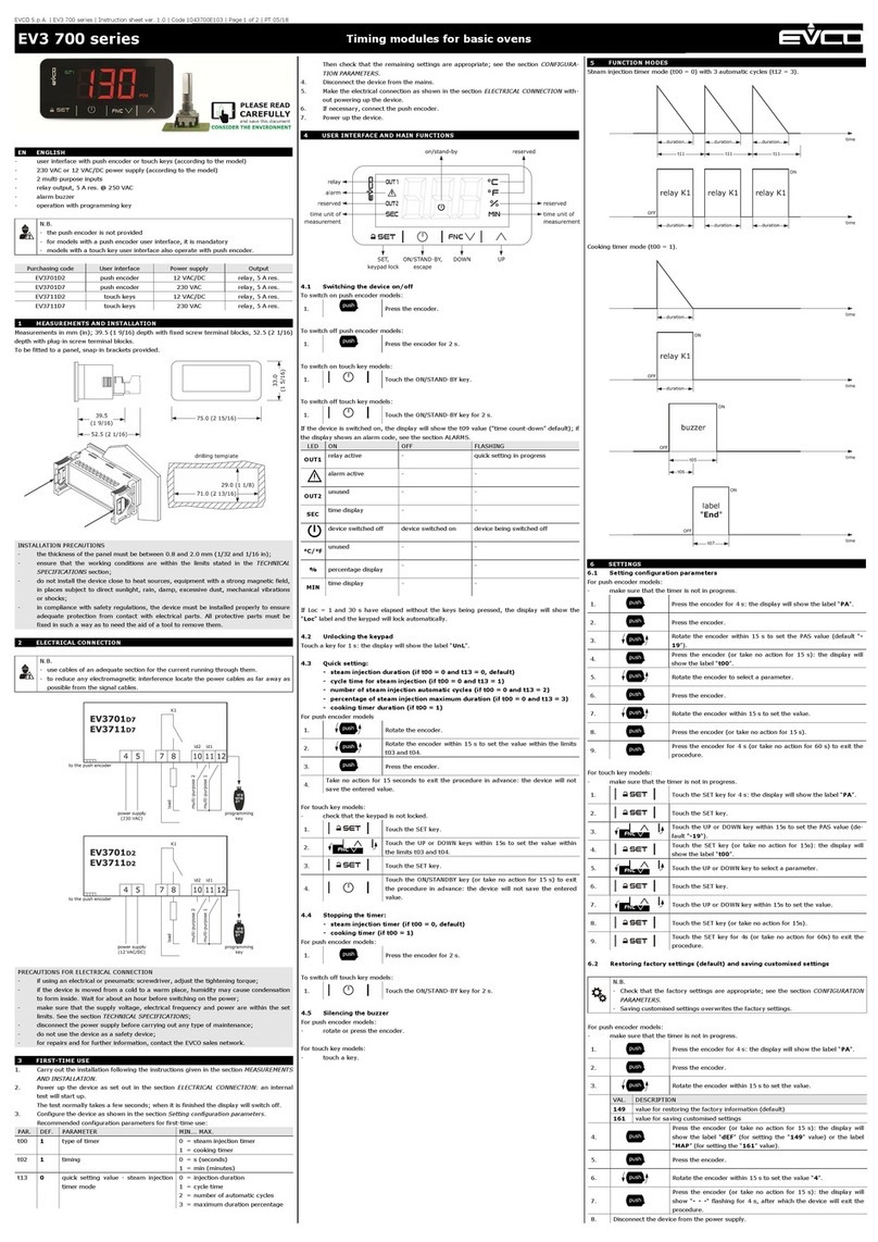
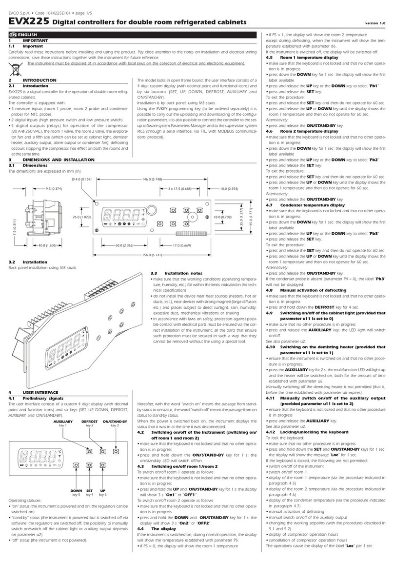
Evco EVJ 500 Series User manual

114J500E4.01 - 04/2021
EVJ 500 series
Temperature/humidity and food processing controllers
WARNING
Read and fully understand
user manual before using
this device.
Failure to follow these
instructions can reslut in
death, serious injury.

114J500E4.01 ·EVJ 500 series
CONTENTS
04/2021
| 2 |
IMPORTANT INFORMATION 5
IMPORTANT SAFETY INFORMATION 6
SAFETY INFORMATION RELATING TO THE PRODUCT 7
1. INTRODUCTION 8
1.1 Description 8
1.2 Models available 8
1.3 Features 8
1.4 Accessories 8
2. TECHNICAL SPECIFICATIONS 10
2.1 Technical specications 10
2.1.1 EVJ 506 / EVJ 526 10
2.1.2 EVJ 536 10
2.2 I/O features 11
2.2.1 EVJ 506 11
2.2.2 EVJ 526 12
2.2.3 EVJ 536 13
3. MECHANICAL ASSEMBLY 14
3.1 Before starting 14
3.2 Information on installation and the environment 14
3.3 Dimensions 15
3.4 Installation 15
3.4.1 Minimum distances 16
4. ELECTRICAL CONNECTIONS 17
4.1 WIRING BEST PRACTICES 17
4.1.1 Wiring guidelines 17
4.1.2 Fixed screw terminal blocks guidelines 17
4.1.3 Permitted lengths of wiring 18
4.2 Wiring diagram 18
5. USER INTERFACE 19
5.1 INTERFACE 19
5.2 TOUCH KEYS 19
5.3 ICONS 19
5.4 CONTROLLER OPERATION 20
5.4.1 Switching the controller ON/OFF 20
5.4.2 Selecting a pre-set programme (EVJ 536 only) 20
5.4.3 Changing the pre-set programme during operation (EVJ 536 only) 21
5.4.4 Functions that can be activated by key 21
5.4.5 Changing the setpoint 22
5.4.6 Stopping a cycle in progress (EVJ 536 only) 23

114J500E4.01 ·EVJ 500 series
CONTENTS
04/2021
| 3 |
5.4.7 Setting the clock 23
5.4.8 Accessing the parameters 24
5.4.9 Programming menu 25
6. DEFROST 26
6.1 Introduction 26
6.1.1 Operating conditions 26
6.1.2 Dripping interval 26
6.1.3 Types of defrost 27
6.2 MODULAR DEFROST: RTC 27
6.3 STANDARD DEFROST 27
6.3.1 Defrost with electrical heaters 27
6.3.2 Defrost with cycle reversed (hot gas) 29
6.3.3 Defrost when compressor stops 31
7. REGULATORS 32
7.1 HEATING/COOLING TEMPERATURE 32
7.1.1 Operation 32
7.2 HEATING/COOLING TEMPERATURE IN THE NEUTRAL ZONE 32
7.2.1 Operation 32
7.3 TEMPERATURE AND DEHUMIDIFICATION WITH THE COMPRESSOR 33
7.3.1 Operation 33
7.3.2 Temperature priority over dehumidication 33
7.4 HUMIDITY 33
7.4.1 Operation 33
7.5 HUMIDITY IN THE NEUTRAL ZONE 34
7.5.1 Operation 34
7.6 Compressor 34
7.6.1 Operating diagrams 35
7.7 DOUBLE COMPRESSOR 36
7.7.1 Operating Diagram 36
7.8 EVAPORATOR FANS 37
7.8.1 Regulator operation 37
7.8.2 Operating mode 37
7.8.3 Operation during defrost 37
7.8.4 Fan operation during dripping 37
7.9 CONDENSER FANS 38
7.9.1 Operation 38
7.10 ENERGY SAVING 38
7.10.1 Operation 38
8. FUNCTIONS 39
8.1 SANITATION (EVJ 526 ONLY) 39

114J500E4.01 ·EVJ 500 series
CONTENTS
04/2021
| 4 |
8.2 AGING (EVJ 536 ONLY) 39
8.3 COPYING THE PARAMETERS 40
8.3.1 Introduction 40
8.3.2 Uploading the parameters from the controller to EVJKEY 40
8.3.3 Downloading the parameters from EVJKEY to the controller 40
9. PARAMETERS 41
9.1 TABLE OF CONFIGURATION PARAMETERS 41
10. DIAGNOSTICS 47
10.1 TABLE OF ALARMS 47

114J500E4.01 ·EVJ 500 series 04/2021
| 5 |
IMPORTANT INFORMATION
Liability and residual risks
EVCO assumes no liability for any damage caused by the following (by way of example; this is not an exhaustive list):
• Installation/useforpurposesotherthanthosespeciedand,inparticular,notadheringtothesafetyprovisionssetout
by current regulations in the country in which the product is installed and/or contained in this manual;
• Useinappliancesthatdonotguaranteesufcientprotectionagainstelectricshocks,wateranddustwithinthe
installation conditions created;
• Useinappliancesthatallowaccesstohazardouspartswithouttheuseofakeyedortooledlockingmechanismwhen
accessing the instrument;
• Tampering and/or modifying the product;
• Installation/use in appliances which do not comply with current regulations in the country in which the product is
installed.
The customer/manufacturer is responsible for ensuring their machine complies with these regulations.
EVCO’s responsibility is limited to the correct and professional use of the product in accordance with regulations and the
instructions contained in this manual and other product support documents.
TocomplywithEMCstandards,observealltheelectricalconnectioninstructions.Asitdependsonthewiringconfigurationas
wellastheloadandtheinstallationtype,compliancemustbeverifiedforthefinalmachineasspecifiedbytherelevantproduct
standard.
Disclaimer
This document is the exclusive property of EVCO. It contains a general description and/or a description of the technical
specifications for the features offered by the products listed herein. This document should not be used to determine the
suitability or reliability of these products in relation to specific user applications. Each user or integration specialist should
conducttheirowncompleteandappropriateriskanalysis,inadditiontocarryingoutaproductevaluationandtestinrelation
to its specific application or use. Users can send us comments and suggestions on how to improve or correct this publication.
Neither EVCO nor any of its associates or subsidiaries shall be held responsible or liable for improper use of the information
contained herein.
EVCOhasapolicyofcontinuousdevelopment,thereforereservestherighttomakechangesandimprovementstoanyproduct
described in this document without prior notice.
The images in this document and other documentation supplied with the product are provided for illustrative purposes only and
may differ from the product itself.
The technical data in this manual is subject to change without prior notice.
Terms and Conditions of use
Permitted use
Thedevicemustbeinstalledandusedinaccordancewiththeinstructionsprovidedand,inparticular,hazardousliveparts
must not be accessible under normal conditions.
The device must be suitably protected from water and dust with regard to its application and must also only be accessible with
the aid of a tool (with the exception of the front panel).
Only qualified personnel may install the product or perform technical support procedures on it.
The customer must only use the product as described in the documentation relating to that product.
Prohibited use
Anyuseotherthanthosedescribedinthe"Permitted use"sectionandintheproductsupportdocumentationisprohibited.
Disposal
The device must be disposed of according to local regulations governing the collection of electrical and electronic
equipment.
Consider the environment
Thecompanystrivestorespecttheenvironment,takingaccountofcustomerrequirements,technologicalinnovations
in terms of materials and the expectations of the community to which we belong. EVCO places great importance on
respectingtheenvironment,encouragingallassociatestobecomeinvolvedwithcompanyvaluesandguaranteeing
safe,healthyandfunctionalworkingconditionsandworkplaces.
Please consider the environment before printing this document.

114J500E4.01 ·EVJ 500 series 04/2021
| 6 |
IMPORTANT SAFETY INFORMATION
Readthisdocumentcarefullybeforeinstallationandtakeallprecautionsbeforeusingthedevice.Onlyusethedevicein
accordance with the methods described in this document. The following safety messages may be repeated several times in
thedocument,toprovideinformationregardingpotentialhazardsortoattractattentiontoinformationwhichmaybeusefulin
explaining or clarifying a procedure.
Thissymbolisusedtoindicateariskofelectricshock.
Itisasafetyindicationandassuch,shouldbeobservedtoavoidpotentialaccidentsorfatalities.
Thissymbolisusedtoindicateariskofseriouspersonalinjury.
Itisasafetyindicationandassuch,shouldbeobservedtoavoidpotentialaccidentsorfatalities.
DANGER
DANGER indicatesasituationofimminentdangerwhich,ifnotavoided,will result in death or serious injury.
WARNING
WARNING indicatesasituationofimminentdangerwhich,ifnotavoided,may result in death or serious injury.
CAUTION
CAUTION indicatesapotentiallyhazardoussituationwhich,ifnotavoided,could cause minor or moderate injury.
NOTICE
NOTICE indicates a situation not related to physical injuries but which
,ifnotavoided,
could damage the equipment.
N.B.Themaintenance,repair,installationanduseofelectricalequipmentmustonlybeentrustedtoqualifiedpersonnel.
QUALIFIED PERSONNEL
Only suitably trained and experienced personnel capable of understanding the content of this manual and all documentation
regardingtheproductareauthorisedtoworkonandwiththisequipment.Furthermore,thepersonnelmusthavecompleted
coursesinsafetyandmustbeabletorecogniseandpreventtheimplieddangers.Thepersonnelmusthavesuitabletraining,
knowledgeandexperienceatatechnicallevel,andbecapableofanticipatinganddetectingpotentialriskscausedbyusing
theproduct,aswellaschangingthesettingsandmodifyingthemechanical,electricandelectronicequipmentfortheentire
systeminwhichtheproductisused.Allpersonnelworkingonandwiththeproductmustbeentirelyfamiliarwiththerelevant
standardsanddirectives,aswellassafetyregulations.

114J500E4.01 ·EVJ 500 series 04/2021
| 7 |
SAFETY INFORMATION RELATING TO THE PRODUCT
Beforecarryingoutanyworkontheequipment,readtheseinstructionscarefully,makingsureyouunderstandeverything.
DANGER
RISK OF ELECTRIC SHOCK, EXPLOSION OR ELECTRIC ARC
• Only use electrically insulated measuring devices and equipment.
• Do not install the equipment while the power supply is connected.
• Switchoffallequipment,includingconnecteddevices,beforeinstallingoruninstallingthedevice.
• Alwaysuseacorrectlycalibratedvoltmetertocheckthesystemisswitchedoff.
• Do not touch the unshielded components or the terminals while they are live.
• Donotopen,disassemble,repairormodifytheproduct.
• Do not expose the equipment to liquids or chemicals.
• All12...24Vac/dcmodelsmustbeindividuallypowered.
• Before applying voltage to the equipment:
• Makesureallprotectiveelements,suchascovers,hatchesandgrilles,arefittedand/orclosed.
• Checkallwiringconnections.
DANGER
RISK OF ELECTRIC SHOCK AND FIRE
• Do not use the device with loads greater than those indicated in the technical specifications.
• Do not exceed the temperature and humidity ranges indicated in the technical specifications.
• Usetherequiredsafetyinterlocks(fusesand/ormagnetothermalswitches)ofasuitablesize.
DANGER
RISK OF ELECTRIC SHOCK OR MALFUNCTIONING OF THE EQUIPMENT
Do not use damaged products or accessories.
Thisdevicewasdesignedtooperateinnon-hazardousenvironments,excludingapplicationsthatgenerate,orcouldpotentially
generate,hazardousatmospheres.Onlyinstallthisdeviceinareasandforapplicationswhicharereliablyfreefromhazardous
atmospheres.
DANGER
RISK OF EXPLOSION
• Onlyinstallandusethisdeviceinsitesthatarenotatrisk.
• Donotinstallorusethisdeviceinapplicationswhicharecapableofgeneratinghazardousatmospheres,suchas
applications that use flammable refrigerants.
WARNING
MALFUNCTIONING OF THE EQUIPMENT
• Perform the wiringcarefully,incompliancewithelectromagneticcompatibilityrequirements.
• Makesurethewiringiscorrectfortheapplication.
• Use shielded cables for all I/O signal and communication cables.
• Minimise the length of the connections as much as possible and avoid winding the cables around electrically connected
parts.
• Thesignalcables(analogueanddigitalinputs,communicationandcorrespondingpowersupplies),powercablesandpower
supply cables for the device must be routed separately.
• Beforeapplyingthepowersupply,checkallthewiringconnections.
• Usetherequiredsafetyinterlockswherepersonneland/orequipmenthazardsexist.
• Installandoperatethisequipmentinacabinetappropriatelyratedforitsintendedenvironmentandsecuredbyakeyedor
tooledlockingmechanism.
• Power line and output circuits must be wired and fused in compliance with local and national regulatory requirements for
the rated current and voltage of the particular equipment.
• Do not use this equipment in safety-critical machine functions.
• Donotdisassemble,repairormodifythisequipment.
• Do not connect wires to unused terminals and/or to terminals labelled “No connection (N.C.)”.
114J500E4.01 ·EVJ 500 series 04/2021
| 8 |
1.1 DESCRIPTION
The controllers in the EVJ 500 series offer a complete range of EVCO solutions for managing:
• Temperature;
• Humidity;
• Foodsanitation;
• Cabinet sterilisation and;
• Foodaging.
1.2 MODELS AVAILABLE
The EVJ 500 series consists of 3 controllers:
• EVJ 506 - Temperature and humidity controller;
• EVJ 526 - Temperature and humidity controller with sanitation function using UV lamps or ozone generators;
• EVJ 536 - Temperature and humidity controller with food processing function.
1.3 FEATURES
The main features of the EVJ 500 series are:
• 2analogueinputs,ofwhich:
• 1analogueinputfortemperature;
• 1analogueinputforhumidity;
• 2voltage-freedigitalinputs,ofwhich:
• 1digitalinputcongurableasananalogueinputbyparameter;
• 6 unsealed relay outputs (can also be supplied sealed on request);
• 1TTLserial;
• EPoCA compatible and;
• Compatible with BMS interface through the MODBUS protocol.
N.B.formoreinformationaboutthefeaturesoftheinputsandoutputs,consultthesection"2.1 Technical specifications" on
page 10.
1.4 ACCESSORIES
The EVJ 500 series has the following accessories:
Type P/n Description
3801000023 230/12VACinsulatedtransformer
--- Temperature probes NTC/PTC
EVIF25TBX BLEmoduletoconnecttotheEVconnectapp
1. INTRODUCTION

114J500E4.01 ·EVJ 500 series 04/2021
| 9 |
Type P/n Description
EVIF25TWX Wi-Fimodule
EVIF22TSX ModuleforTTL/RS-485serialinterface
EVIF23TSX ModuleforTTL/RS-485serialinterfacewithbuilt-inclock
EVJKEY ProgrammingkeyforEVJmodels.

114J500E4.01 ·EVJ 500 series 04/2021
|10|
2. TECHNICAL SPECIFICATIONS
AllthesystemcomponentsoftheEVJ 500 controllers meet the requirements of the European Community (EC) for open
equipment.Theymustbeinstalledinacasingorotherlocationdesignatedforthespecificambientconditionsandtokeepthe
possibility of involuntary contact with dangerous electrical voltages to a minimum. Use metal casings to improve the immunity
of the EVJ 500 system to electromagnetic fields. This equipment meets EU requirements as shown in the tables below.
WARNING
MALFUNCTIONING OF THE EQUIPMENT
Do not exceed the nominal values given in this section.
2.1 TECHNICAL SPECIFICATIONS
2.1.1 EVJ 506 / EVJ 526
Type Description
The product complies with the following harmonised
standards:
EN60730-1andEN60730-2-9
Device construction: Built-in electronic device
Device purpose: Operating control device
Type of action: 1
Pollution category: 2
Overvoltage category: III
Rated impulse withstand voltage: 4000 V
Power supply: 12Vac/dc,±10%,50/60Hz
Consumption: 10VAmaximum
Ambientoperatingconditions:
0...55°C(32...131°F)10…90%RHnon-condensing
Transportation and storage conditions:
-25...70°C(-13...158°F)10…90%RHnon-condensing
Software class: A
Environmental front protection: IP65
Clock(RTC): Built-in lithium battery
Clockdrift: ≤60s/monthat25°C(77°F)
Battery life: >6monthsat25°C(77°F)
Battery charging time: 24 h through device’s power supply
2.1.2 EVJ 536
Type Description
The product complies with the following harmonised
standards:
EN60730-1andEN60730-2-9
Device construction: Built-in electronic device
Device purpose: Operating control device
Type of action: 1
Pollution category: 2
Overvoltage category: III
Rated impulse withstand voltage: 4000 V
Power supply: 12Vac/dc,±10%,50/60Hz
Consumption: 10VAmaximum
Ambientoperatingconditions:
0...55°C(32...131°F)10…90%RHnon-condensing
Transportation and storage conditions:
-25...70°C(-13...158°F)10…90%RHnon-condensing
Software class: A
Environmental front protection: IP65
Clock(RTC): Built-in lithium battery
Clockdrift: ≤60s/monthat25°C(77°F)
Battery life: >6monthsat25°C(77°F)
Battery charging time: 24 h through device’s power supply

114J500E4.01 ·EVJ 500 series 04/2021
|11|
2.2 I/O FEATURES
2.2.1 EVJ 506
Type Description
Digital inputs: 2 voltage-free digital inputs
(ID3 also configurable as analogue
input Pb3 with Pr3≠0)
Analogueinputsfortemperature: 2 analogue inputs for NTC or PTC or humidity probe
Digitaloutputwithnon-hazardousvoltage(SELV): 6 digital outputs
Serial: 1TTLserial
Analogue input features
Default
NTC
10 kΩ at 25 °C
BETA 3435
PTC
KTY 81-121
990 Ω at 25 °C
RH
EVHTP5
•
0Digital input
Pb1
Temperature probe
• • --- ---
Pb2
Humidity probe
(EVHTP5•0)
--- --- •---
Pb3
(If Pr3=5)
Evaporator probe
• • --- •
Range --- -50...120°C
(-58...248°F)
-50...150°C
(-58...302°F) 5...95%RH ---
Resolution --- 0.1°C(1°F) 1% ---
Input
impedance --- 10kΩ 990Ω --- ---
Digital output features
Relay output Default Description Load (at 250 Vac) Type of load
Out1 Compressor SPST 30A Resistive
Out2 Heating SPDT 8A Resistive
Out3 Light SPST 16A Resistive
Out4 Humidification SPST 8A Resistive
Out5 Fans SPST 5A Resistive
Out6 Defrost SPDT 8A Resistive

114J500E4.01 ·EVJ 500 series 04/2021
|12|
2.2.2 EVJ 526
Type Description
Digital inputs: 2 voltage-free digital inputs
(ID3 also configurable as analogue
input Pb3 with Pr3≠0)
Analogueinputsfortemperature: 2 analogue inputs for NTC or PTC or humidity probe
Digitaloutputwithnon-hazardousvoltage(SELV): 6 digital outputs
Serial: 1TTLserial
Analogue input features
Default
NTC
10 kΩ at 25 °C
BETA 3435
PTC
KTY 81-121
990 Ω at 25 °C
RH
EVHTP5
•
0Digital input
Pb1
Temperature probe
• • --- ---
Pb2
Humidity probe
(EVHTP5•0)
--- --- •---
Pb3
(If Pr3=5)
Evaporator probe
• • --- •
Range --- -50...120°C
(-58...248°F)
-50...150°C
(-58...302°F) 5...95%RH ---
Resolution --- 0.1°C(1°F) 1% ---
Input
impedance --- 10kΩ 990Ω --- ---
Digital output features
Relay output Default Description Load (at 250 Vac) Type of load
Out1 Compressor SPST 30A Resistive
Out2 Heating SPDT 8A Resistive
Out3 Light SPST 16A Resistive
Out4 Humidification SPST 8A Resistive
Out5 Fans SPST 5A Resistive
Out6 Defrost SPDT 8A Resistive

114J500E4.01 ·EVJ 500 series 04/2021
|13|
2.2.3 EVJ 536
Type Description
Digital inputs: 2 voltage-free digital inputs
(ID3 also configurable as analogue
input Pb3 with Pr3≠0)
Analogueinputsfortemperature: 2 analogue inputs for NTC or PTC or humidity probe
Digitaloutputwithnon-hazardousvoltage(SELV): 6 digital outputs
Serial: 1TTLserial
Analogue input features
Default
NTC
10 kΩ at 25 °C
BETA 3435
PTC
KTY 81-121
990 Ω at 25 °C
RH
EVHTP520 Digital input
Pb1
Temperature probe
• • --- ---
Pb2
Humidity probe
(EVHTP520)
--- --- •---
Pb3
(If Pr3=5)
Evaporator probe
• • --- •
Range --- -50...120°C
(-58...248°F)
-50...150°C
(-58...302°F) 5...95%RH ---
Resolution --- 0.1°C(1°F) 1% ---
Input
impedance --- 10kΩ 990Ω --- ---
Digital output features
Relay output Default Description Load (at 250 Vac) Type of load
Out1 Compressor SPST 30A Resistive
Out2 Heating SPDT 8A Resistive
Out3 Light SPST 16A Resistive
Out4 Humidification SPST 8A Resistive
Out5 Fans SPST 5A Resistive
Out6 Defrost SPDT 8A Resistive

114J500E4.01 ·EVJ 500 series 04/2021
|14|
3. MECHANICAL ASSEMBLY
3.1 BEFORE STARTING
Read this manually carefully before installing the system.
Inparticular,thesafetyinstructions,electricalrequirementsandcurrentregulationsforthemachineortheprocessinwhich
this device is involved must be observed. The use and application of the information contained herein require experience in the
designandprogrammingofautomatedcontrolsystems.Onlytheuser,systemintegratorormachinebuildercanbeawareofall
theconditionsandfactorspresentduringtheinstallation,configuration,operationandmaintenanceofthemachineorprocess,
andcanthereforedeterminetheassociatedautomationequipmentandtherelatedsafetiesandinterlockswhichcanbe
effectively and properly used. When selecting automation and control equipment and any other related equipment or software
foraparticularapplication,alwaysconsideralltheapplicablelocal,regionalornationalstandardsand/orregulations.
WARNING
REGULATORY NON-COMPLIANCE
Makesurealltheequipmentusedandthesystemscomplywithalltheapplicablelocal,regionalandnationalregulations.
3.2 INFORMATION ON INSTALLATION AND THE ENVIRONMENT
Beforecarryingoutanyworkontheequipment,readtheseinstructionscarefully,makingsureyouunderstandeverything.
DANGER
RISK OF ELECTRIC SHOCK, EXPLOSION OR ELECTRIC ARC
• Only use electrically insulated measuring devices and equipment.
• Do not install the equipment while the power supply is connected.
• Switchoffallequipment,includingconnecteddevices,beforeinstallingoruninstallingthedevice.
• Alwaysuseacorrectlycalibratedvoltmetertocheckthesystemisswitchedoff.
• Do not touch the unshielded components or the terminals while they are live.
• Donotopen,disassemble,repairormodifytheproduct.
• Do not expose the equipment to liquids or chemicals.
• Before applying voltage to the equipment:
• Makesureallprotectiveelements,suchascovers,hatchesandgrilles,arefittedand/orclosed.
• Checkallwiringconnections.
Thisdevicewasdesignedtooperateinnon-hazardousenvironments,excludingapplicationsthatgenerate,orcouldpotentially
generate,hazardousatmospheres.Onlyinstallthisdeviceinareasandforapplicationswhicharereliablyfreefromhazardous
atmospheres.
DANGER
RISK OF EXPLOSION
• Only install and use this deviceinsitesthatarenotatrisk.
• Donotinstallorusethisdeviceinapplicationswhicharecapableofgeneratinghazardousatmospheres,suchas
applications that use flammable refrigerants.

114J500E4.01 ·EVJ 500 series 04/2021
|15|
WARNING
MALFUNCTIONING OF THE EQUIPMENT
• Performthewiringcarefully,incompliancewithelectromagneticcompatibilityandsafetyrequirements.
• Makesurethewiringiscorrectfortheapplication.
• Use shielded cables for all I/O signal and communication cables.
• Minimise the length of the connections as much as possible and avoid winding the cables around electrically connected
parts.
• Thesignalcables(analogueanddigitalinputs,communicationandcorrespondingpowersupplies),powercablesandpower
supply cables for the device must be routed separately.
• Beforeapplyingthepowersupply,checkallthewiringconnections.
• Usetherequiredsafetyinterlockswherepersonneland/orequipmenthazardsexist.
• Installandoperatethisequipmentinacabinetappropriatelyratedforitsintendedenvironmentandsecuredbyakeyedor
tooledlockingmechanism.
• Power line and output circuits must be wired and fused in compliance with local and national regulatory requirements for
the rated current and voltage of the particular equipment.
• Do not use this equipment in safety-critical machine functions.
• Donotdisassemble,repairormodifythisequipment.
• Do not connect wires to unused terminals and/or to terminals labelled “No connection “(N.C.)”.
3.3 DIMENSIONS
-17.560
%
Over
Temp
Door open
°c
111.4 (4.38)
76.4 (3.01)
48.5 (1.91)
Fig. 1. EVJ 500 series dimensions
3.4 INSTALLATION
1
07
,
6
(
4
.2
4
)
72,6 (2.85)
mm (in.)
0.8...2
(0.03...0.07)
Fig. 2. EVJ 500 series installation

114J500E4.01 ·EVJ 500 series 04/2021
|16|
3.4.1 Minimum distances
40 (1.57)
40 (1.57)
mm (in.)
40 (1.57)
40 (1.57)
Fig. 3. EVJ 500 series minimum installation distances

114J500E4.01 ·EVJ 500 series 04/2021
|17|
4. ELECTRICAL CONNECTIONS
4.1 WIRING BEST PRACTICES
The following information describes the wiring guidelines and best practices which should be observed when using the
equipment described in this manual.
DANGER
RISK OF ELECTRIC SHOCK, EXPLOSION OR ELECTRIC ARC
• Only use electrically insulated measuring devices and equipment.
• Do not install the equipment while the power supply is connected.
• Switchoffallequipment,includingconnecteddevices,beforeinstallingoruninstallingthedevice.
• Alwaysuseacorrectlycalibratedvoltmetertocheckthesystemisswitchedoff.
• Do not touch the unshielded components or the terminals while they are live.
• Donotopen,disassemble,repairormodifytheproduct.
• Do not expose the equipment to liquids or chemicals.
• Before applying voltage to the equipment:
• Makesureallprotectiveelements,suchascovers,hatchesandgrilles,arefittedand/orclosed.
• Checkallwiringconnections.
4.1.1 Wiring guidelines
Whenwiringthecontrollers,observethefollowinginstructions:
• TheI/Oandcommunicationwiringmustbekeptseparatefromthepowersupplywiring.Thesetwotypesofwiringmust
be routed in separate ducts.
• Makesuretheoperatingenvironmentandconditionsfallwithinthespeciedvalues.
• Usewireswiththecorrectdiameter,suitedtothevoltageandcurrentrequirements.
• Use copper conductors (compulsory).
• Use shielded twisted pair cables for analogue/digital I/O connections.
Use correctly earthed shielded cables for all analogue inputs or outputs and for communication connections. If shielded cables
arenotusedfortheseconnections,electromagneticinterferencecouldcausethesignaltodeteriorate.Deterioratedsignals
can lead to unpredictable operation of the controller or modules and connected equipment.
WARNING
MALFUNCTIONING OF THE EQUIPMENT
• Performthewiringcarefully,incompliancewithelectromagneticcompatibilityandsafetyrequirements.
• Makesurethewiringiscorrectfortheapplication.
• Use shielded cables for all I/O signal and communication cables.
• Minimise the length of the connections as much as possible and avoid winding the cables around electrically connected
parts.
• Thesignalcables(analogueanddigitalinputs,communicationandcorrespondingpowersupplies),powercablesandpower
supply cables for the device must be routed separately.
• Beforeapplyingthepowersupply,checkallthewiringconnections.
• Usetherequiredsafetyinterlockswherepersonneland/orequipmenthazardsexist.
• Installandoperatethisequipmentinacabinetappropriatelyratedforitsintendedenvironmentandsecuredbyakeyedor
tooledlockingmechanism.
• Power line and output circuits must be wired and fused in compliance with local and national regulatory requirements for
the rated current and voltage of the particular equipment.
• Do not use this equipment in safety-critical machine functions.
• Donotdisassemble,repairormodifythisequipment.
• Do not connect wires to unused terminals and/or to terminals labelled “No connection (N.C.)”.
4.1.2 Fixed screw terminal blocks guidelines
Suitable wiring for power supply and I/O SELV
Passo 5,08 mm (0.199 in.)
Ø 3.5 mm (0.14 in.)
mm2
AWG
0.2…2.5
24…14
0.2…2.5
24…14
0.25…2.5
22...14
2 x 0.25…1
2 x 22…18
2 x 0.2…1.5
2 x 24…16
2 x 0.2…1
2 x 24…18
2 x 0.5...1.5
2 x 20...16
mm
in.
7
0.28 C0.5...0.6
4.42...5.31
N•m
lb-in
0.25…2.5
22...14
Fig. 4. Suitable wiring for power supply and I/O SELV

114J500E4.01 ·EVJ 500 series 04/2021
|18|
4.1.3 Permitted lengths of wiring
NOTICE
DEVICE NOT WORKING
• Whenconnectingtheprobes,thedigitalinputsandthepowersupply,usecableswithamaximumlengthof
10m(32.80ft).
• WhenconnectingtheTTLserial,usecableswithamaximumlengthof1m(3.28ft.).
• Whenconnectingthepowersupplyofthecontrollerandtherelayoutputs,usecableswithamaximumlengthof
10m(32.80ft.).
4.2 WIRING DIAGRAM
123 4 5 6
Pb1
Pb2
ID1
ID3
Power supply
910 11 12 13 14 15 16
17 18 19 20 21 22 23
Pr3=0
N.C.
TTL
Out1
Out2
Out3
Out4
Out5
Out6
123 4 5 6
Pb1
Pb2
ID1
Pb3
Power supply
910 11 12 13 14 15 16
17 18 19 20 21 22 23
Pr3≠0
N.C.
TTL
Out1
Out2
Out3
(*)
(*) = Maximum 10 A (*) = Maximum 10 A
(*)
Out4
Out5
Out6
Fig. 5. Wiring diagram
TERMINALS
1-2 Relay output Out3 (Light) 12-15-16 Relay output Out2 (Heating)
3No connection N.C. 17-21 Digital input ID1
4-5-6 Relay output Out6 (Defrost) 18-21 Digital input ID3 if Pr3=0
Probe input Pb3 if Pr3≠0
8-10 Relay output Out1 (Compressor) 19-21 Probe input Pb2 (Humidity)
11-12 Relay output Out5 (Fans) 20-21 Probe input Pb1 (Temperature)
12-14 Relay output Out4 (Humidification) 22-23 Power supply input

114J500E4.01 ·EVJ 500 series 04/2021
|19|
5. USER INTERFACE
5.1 INTERFACE
-17.560
%
Over
Temp
Door open
°c
Fig. 6. User interface
5.2 TOUCH KEYS
Adescriptionofthetouchkeysisgivenbelow:
Key... Press and release to... Press for at least 3 seconds to...
--- • (From home page)Accessthecongurationmenu
• (From stand-by)Accesstheprogrammingmenu
• Gobackonelevel
• Exit a function
• Switch device on/off
• Stop regulation
• Decrease a value
• Move within a menu ---
• Increase a value
• Move within a menu
• AccesstheAUXmenu
---
Active/Deactivatethelightrelayoutput ---
• Conrmaselectedvalue/function
• Accessthesetpointmenu ---
5.3 ICONS
Icon ON Flashing OFF
• Cooling request
• Dehumidicationrequest Protection delay ON CompressorOFF
Defrost active
• Defrost delay ON
• Dripping ON
---
Evaporator fans ON
• Evaporator fan activation
delay
ON
• Humidication/dehumidicationcycleON
EvaporatorfansOFF
• Humidicationrequest
• Humidication
digital output ON --- ---
• Dehumidicationrequest
• Dehumidification digital output ON Dehumidification delay with compressor ON ---
• Heating request
• Heating digital output ON --- ---
HACCP
HACCPalarmsaved NewHACCPalarmrecorded ---
Energy saving ON ---
EnergysavingOFF
Maintenance request Remote connection ---
CTemperature displayed in °C --- ---
FTemperaturedisplayedin°F --- ---
%Humiditydisplayedin% --- ---
AUX • AUXfunctionON
• AUXdigitaloutputON --- AUXfunctionOFF

114J500E4.01 ·EVJ 500 series 04/2021
| 20 |
Icon ON Flashing OFF
LightrelayONbykey LightrelayONbydoorswitch LightrelayOFF
--- Alarminprogress ---
• Probe value below the setpoint
• Probe value above the setpoint --- ---
Keypadlocked --- ---
Keypadunlocked --- ---
Door switch open Door switch closed ---
Activecycle Cycle suspended due to activation of other
function Inactive cycle
EVJ 526 ONLY
Sanitation in progress with device ON Sanitation interval (if device is ON)
5.4 CONTROLLER OPERATION
5.4.1 Switching the controller ON/OFF
Toswitchthecontrolleron/off,pressthe keyforatleast3seconds.
-17.560
%
Over
Temp
°c
Over
Temp
Fig. 7. Main screen Fig. 8. Controller switching off
N.B.: the icon will be displayed for a few seconds as shown in "Fig. 8. Controller switching off" on page 20 and then the
display will go off. The iconwillbedisplayedwhenoneofthekeysispressed.
5.4.2 Selecting a pre-set programme (EVJ 536 only)
To select one of the six pre-set operating programmes:
-17.560
%
Over
Temp
Program 01
Stop
°c
1
Program 02
Program 04
Program 05
Program 06
Menu
1
2
2
Program 01
Fig. 9. Selecting the operating programme
This manual suits for next models
3
Table of contents
Other Evco Controllers manuals

Evco
Evco EV3143 User manual

Evco
Evco Vcolor 579 User guide

Evco
Evco C-PRO CLIMA SYSTEMA User guide

Evco
Evco EVJ 800 series User guide

Evco
Evco EV8338 User manual

Evco
Evco EVJ254 User manual

Evco
Evco c-pro 3 OEM HRV User guide

Evco
Evco Vcolor 379 User guide

Evco
Evco EVXS815 User guide

Evco
Evco EV3B71 User manual

Evco
Evco EV3143 User manual

Evco
Evco C-PRO NANO User manual

Evco
Evco EVJS 800 Series User guide

Evco
Evco EVF User manual

Evco
Evco EVD EXP User manual

Evco
Evco EVF204 User manual

Evco
Evco Vcolor 818 User guide

Evco
Evco C-pro 3 giga User manual

Evco
Evco EV3802 User manual

Evco
Evco c-pro 3 nano CHIL Instructions for use