ZoneVu ZVR-110 User manual

ZVR-110
SECURITY with VISION
TELEMETRY RECEIVER
USERS MANUAL

MEYERTECH DIVISION ISSUE 01
Page 2
CONTENTS
1. ZVR-110 WELCOME 3
2. FEATURES 3
3. INSTALLATION 3
3.1 RELAY LINK SETTINGS 4
3.2 CONNECTING THE ZVR-110 4
3.3 CAMERA NUMBER ASSIGNMENT 5
4. SELF TEST DIAGNOSTICS 6
5. SPECIFICATIONS 6
5.1 ELECTRICAL 6
5.2 PHYSICAL 6
6. CONNECTION DIAGRAM 8
7. TROUBLE SHOOTING GUIDE 9
8. DECLARATION OF CONFORMITY 10
9. PRODUCT WARRANTY 11
10. DOCUMENT HISTORY 12
Whilst every effort has been made to confirm the information in this document is correct,
MEYERTECH DIVISION cannot accept any liability for any errors, omissions and or incorrect
information contained within this document.
No part of this document may be reproduced or distributed in any form or by any means
without prior written consent from MEYERTECH DIVISION.
MEYERTECH DIVISION are committed to continuous product development and therefore
reserve the right to change specifications without notice.
1997 ALL RIGHTS RESERVED.

MEYERTECH DIVISION ISSUE 01
Page 3
1. ZVR-110 WELCOME
Thank you for purchasing the ZoneVu ZVR-110 Telemetry Receiver.
The ZVR-110 is a powerful, low cost telemetry receiver offering an economical Wash/Wipe solution.
With the ability to operate over coax or twisted pair RS-422, the ZVR-110 is compact enough to be
mounted easily inside the smallest of camera housing and on board self-test and diagnostic facilities
minimize installation and commissioning time.
MEYERTECH are dedicated to customer service and support. If you have any questions or
problems, our staff will be pleased to assist you on the technical help lines listed on page 15.
2. FEATURES
♦Two relay outputs configurable as Wash, Wipe, Lamp, Auxiliary 1 or Auxiliary 2.
♦Function and PSU LED’s.
♦Anti Tamper Alarm.
♦Coaxial or RS-422 Telemetry.
♦Compatible with the full range of ZoneVu products.
♦Self Test Diagnostics.
3NSTALLATION
3. INSTALLATION
To obtain the optimum performance from your ZVR-110 please take time to read this manual before
commencing installation. If you have any questions or problems our staff will be pleased to assist you
on the technical help lines listed on page 15.
Unpack the ZVR-110 and check the contents against the list below.
♦ZVR-110 PCB

MEYERTECH DIVISION ISSUE 01
Page 4
3.1 RELAY LINK SETTINGS
The ZVR-110 PCB is populated with a number of jumper links which require setting at installation.
These links allocate relay functions and are all located down one side of the PCB as indicated below
(also see Connection Diagram on page 8).
Insert a maximum of two jumpers, to select the receiver functions required.
3.2 CONNECTING THE ZVR-110
Connect up the ZVR-110 in accordance with the accompanying wiring diagram, paying special
attention to the maximum ratings and the notes below.
1. The ZVR-110 MUST be earthed at the AC input supply terminal.
2. NEVER run cables directly under the PCB as this may interfere with the operation of the
Telemetry ZVR-110 and other camera head equipment.
3. ALWAYS use Screened cables for low voltage and signal cables ensuring the screen is
connected to 0V or Earth.
4. AVOID looming cables of differing characteristics together E.G. Video cables with cables
carrying mains power.
5. If the ZVR-110 is to be operated over twisted pair cable ensure the screen is connected to 0V.
6. The maximum cable run for Twisted Pair is typically 2Km.
7. The maximum cable run for VICTA is typically 750m.
8. The maximum number of Telemetry Receivers that can be connected to a driver output is 32.
ZVR-110 PCB
WP
A2
LP
WS
A1
CONFIGURATION
LINKS
RLY 1 RLY 2

MEYERTECH DIVISION ISSUE 01
Page 5
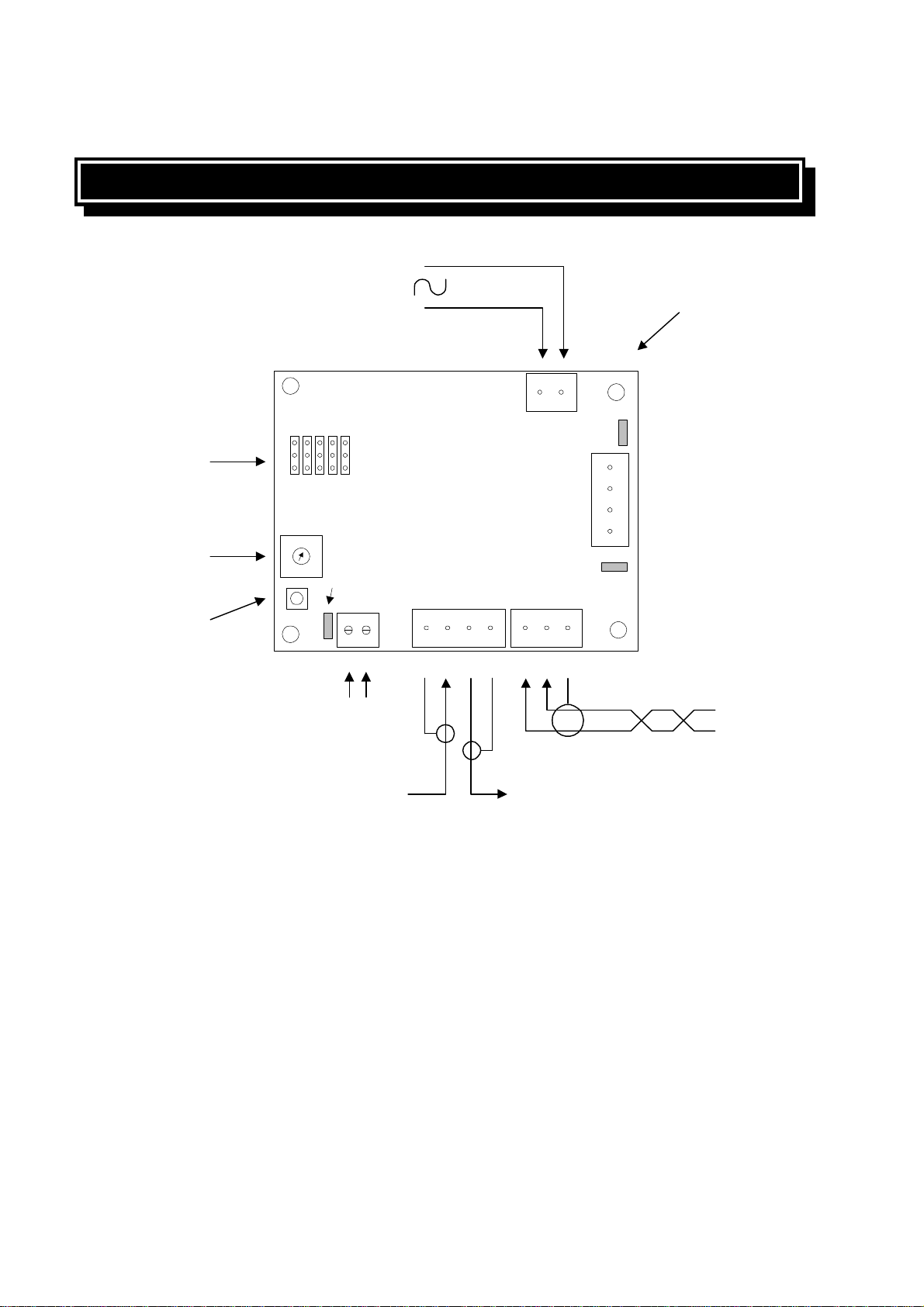
9. The cable used to wire the secondary of the transformer should be a minimum of 0-5mm2.
3.3 CAMERA NUMBER ASSIGNMENT
When operating the ZVR-110 using RS-422 telemetry, a receiver address must be set up which
corresponds to the connected matrix output. If operating the ZVR-110 over Meyertech VICTA coax
telemetry, no receiver address is necessary.
Turn the Program Switch to position “0”. Power the receiver up with the Test/Enter button held down.
Check that the program LED illuminates. Note, at this point the receiver is set to operate in VICTA
telemetry mode.
To set the ZVR-110 receiver address:
1. To set the least significant digit (units), turn the Program Switch to position “A”. Press the
Test/Enter button and observe the Program LED flash once. Turn the Program Switch to the
appropriate number. E.g. 1 for camera 001, 5 for camera 015. Press the Test/Enter button
and once again observe the Program LED flash once. The least significant digit of the camera
number is now set.
2. To set the next least significant digit (tens), turn the Program Switch to position “B”. Press the
Test/Enter button and observe the Program LED flash once. Turn the Program Switch to the
appropriate number. E.g. 0 for camera 001, 1 for camera 015. Press the Test/Enter button
and once again observe the Program LED flash once. The next least significant digit of the
camera number is now set.
3. To set the most significant digit (hundreds), turn the Program Switch to position “C”. Press the
Test/Enter button and observe the Program LED flash once. Turn the Program Switch to the
appropriate number. E.g. 0 for camera 001, 0 for camera 015. Press the Test/Enter button
and once again observe the Program LED flash once. The most significant digit of the camera
number is now set.
4. Exit the program mode by removing the power connector and re-power the unit. normally.

MEYERTECH DIVISION ISSUE 01
Page 6
4. SELF TEST DIAGNOSTICS
The ZVR-110 features a set of diagnostics to test the function of both relays
Select the function required for testing by turning the Program Switch to the position in shown in
the table below.
Program Switch Function Tested
0Relay 1
1Relay 2
Activate the diagnostic test function selected by pressing the Test/Enter Switch.
5. SPECIFICATIONS
5.1 ELECTRICAL
POWER INPUT - 12VAC Power Supply.
CURRENT CONSUMPTION -35mA
RELAYS -Normally Open 5A max.
5.2 PHYSICAL
DIMENSIONS - 86mm x 67mm x 30mm max.
WEIGHT -
TEMPERATURE - Operational 0 Degrees to 40 Degrees C
- Storage minus 20 Degrees to plus 60 Degrees C
- Humidity 10% to 95% (Non-condensing)
VIDEO I/O - 4 pin Plug in Terminal Block

MEYERTECH DIVISION ISSUE 01
Page 7
TAMPER -2 pin Terminal Block
TELEMETRY -3 pin Plug in Terminal
2 wire RS-422 ( Twisted Pair plus screen )
PROTOCOL -VICTAcoax telemetry.
RS422 twisted pair (Telemetry / Network Communications)
ZoneVu commands and data are transmitted in PACKETS. Each
Packet has a unique HEADER to identify its destination and a
common TERMINATOR to identify the end of the data Packet.
The Packet Headers and the Packet Terminator are formed from
non-printable ASCII characters.
Commands and data are formed from printable ASCII characters.
ASCII NUL characters are used to separate data fields.
Baud rate -9600 baud
Parity -none
Stop bits -1
Flow control -none
Data bits -8

MEYERTECH DIVISION ISSUE 01
Page 8
6. CONNECTION DIAGRAM
ZVR-110
PCB
BCD
CONFIGURATION
LINKS
PROGRAM
SWITCH
TEST/
ENTER
SWITCH
TAMPER
VIDEO FROM
CAMERA VIDEO TO
MONITOR
RS-422
TELEMETRY
Rx+ Rx- SCREEN
12V AC SUPPLY
(PCB ONLY) 4 LOCATION
HOLES 4mm dia.
spaced 67mm by
59.5mm apart
PROG
LED Rx LED
POWER
LED

MEYERTECH DIVISION ISSUE 01
Page 9
7. TROUBLE SHOOTING GUIDE
This Trouble Shooting Guide should be used in the first instance of encountering any problems with
the ZVR-110. If problems persist, contact MEYERTECH on the Technical Help line numbers given
on page 15.
Symptom Solution

MEYERTECH DIVISION ISSUE 01
Page 10
8. DECLARATION OF CONFORMITY
Manufacture’s Name: MEYERTECH DIVISION
Manufacture’s Address: MEYERTECH Division
Office Block One
Southlink Business Park
Oldham
OL4 1DE
declares, that the product(s):
Product Name :ZVR-110 Telemetry Receiver
Model(s) : All
Product Options : All
conforms to the following Product Specifications :
EN55022 CLASS B
EN50093
Supplementary Information :
MEYERTECH declare under our sole responsibility that the product to which this
declaration relates, is in conformity with the protection requirements of council directive
89/336/EEC on the approximation of the laws of the member states relating to
electromagnetic compatibility.
SIGNED -
S K MEYERS
Director MEYERTECH DIVISION
ISSUED THIS DAY : 3rd June 1997
European Contact : Meyertech Division (Head Office), Office Block One,
Southlink Business Park, Oldham, England, OL4 1DE.
EC DECLARATION OF CONFORMITY ACCORDING
TO ARTICLE 10 OF COUNCIL DIRECTIVE 89/336/EEC

MEYERTECH DIVISION ISSUE 01
Page 11
9. PRODUCT WARRANTY
MEYERTECH DIVISION warrants that at the time of shipment the products manufactured by
Meyertech will be free from defects in material and workmanship.
Should any defects appear within twelve months from date of shipment, Meyertech Division shall at
it’s sole discretion repair or replace the defective material. Such material shall not be accepted for
return or repair without prior notification of Meyertech Division.
Return shipments to Meyertech Division shall be at the customers expense. Meyertech Division will
return said equipment prepaid via best way.
This warranty is in lieu of and excludes any and all other expressed or implied warranties of
merchantability or fitness, or otherwise. Items manufactured by any supplier other than Meyertech
Division shall bear only the warranty made by the manufacturer of that product, and Meyertech
Division assumes no responsibility for the performance or reliability of that product.
Meyertech Division will not be liable for any special or consequential damages, or for loss, damages,
or expense directly or indirectly arising from the use of the products, or any inability to use them
either separately or in combination with any other equipment or material or from any other cause.
This warranty does not extend to any product manufactured by Meyertech Division which has been
subject to misuse, neglect, accident, war, civil disturbance, terrorist acts, improper installation, act of
God, or in violation of the instructions supplied by Meyertech Division.

MEYERTECH DIVISION ISSUE 01
Page 12
10. DOCUMENT HISTORY
ZVR-110 Telemetry Receiver Users Manual : MAN-110
ISSUE DATE CHANGE RECORD
01 16 Sept 1997 First Issue

MEYERTECH DIVISION ISSUE 01
Page 13
NOTES

MEYERTECH DIVISION ISSUE 01
Page 14
NOTES

MEYERTECH DIVISION ISSUE 01
Page 15
MEYERTECH DIVISION
SECURITY with VISION
Office Block One
Southlink Business Park
Oldham
England
OL4 1DE
Sales Support
(+44 (161) 628 8406
2+44 (161) 628 9811
Technical Support
Oldham (+44 (161) 628 8406
Kirton (+44 (1652) 640740
Table of contents
Other ZoneVu Receiver manuals