manuals.online logo
Brands
  1. Home
  2. •
  3. Brands
  4. •
  5. HES
  6. •
  7. Lock
  8. •
  9. HES 1006 series User manual

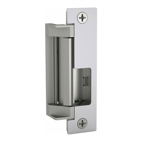
HES 1006 series User manual

1006 SERIES
HEAVY DUTY ELECTRIC STRIKES
Hanchett Entry Systems, Inc.
22630 N. 17th Ave.
Phoenix, AZ 85027
www.hesinnovations.com
1-11/16
[42.86]
3-3/8
[85.70]
1-1/2
[38.10]
1-3/4
[44.44]
2-1/16
[52.39]
1006 SERIES DIMENSIONS
DIMENSIONS:
INCH/MM
AD, HD, ND, TD -
OPTION
FACEPLATE
A, H, HT, N,T -
OPTION
FACEPLATE
AM, HM, NM -
OPTION
FACEPLATE
KM - OPTION
FACEPLATE
Z - OPTION
FACEPLATE
J, E - OPTION
FACEPLATE
K - OPTION
FACEPLATE
KD - OPTION
FACEPLATE
1-23/32
[43.64]
1-37/64
[40.08]
2-7/8
[73.02]
1-9/64
[28.83]
1/8
[3.17]
1-15/32
[37.29]
1-25/64
[35.48]
5/16
[7.79]
3-1/8
[79.37]
7/8
[22.23]
19/32
[15.46] 1-15/32
[37.29]
1-3/32
[27.81]
5/32
[3.97] 3-1/8
[79.37]
23/32
[18.26]
29/32
[23.39]
1-11/32
[34.11]
27/32
[21.46]
NOTE: Drawings are not to scale. This information is subject to change without notice. For questions, consult HES technical service helpline, 800-626-7590.
R - OPTION
FACEPLATE
1-3/4
[44.45]
27/32
[21.46]
23/32
[18.22]
4-1/8
[104.78]
2-1/8
[52.39]
3/4
[20.33]
3/8
[10.68]
3-3/8
[85.70]
4-7/8
[123.83]
5/8
[15.88]
1-1/4
[31.75]
1-11/32
[34.11]
23/32
[18.14]
4-7/8
[123.83]
4-1/8
[104.78]
1-1/16
[26.72]
©HES 2005
1
4036006.001 rev B
C
L= center line of faceplate
(2nd line = center line of opening)
INSTALLATION INSTRUCTIONS • Please read carefully before attempting installation.
Technical Service Dept. Helpline 800-626-7590 623-582-4626
1. Prepare door jamb per appropriate
template detail. (See Figures 1-5). (See
NOTE 1.)
2. Install mounting tabs, when applicable.
(P/N 152: universal mounting tabs) using
four 10-32 UNF screws (see Figure 5). Do
not tighten.
3. Unplug wire pigtail from electric strike.
4. Connect wires coming from the low
voltage power source (see wiring
diagrams and electrical specifications on
page 6) to the electric strike pigtail.
5. Re-connect the pigtail to the electric
strike.
6. Install electric strike and option faceplate
to jamb, using two 12–24 UNC machine
screws or wood screws provided in the
option package.
7. Tighten the four10-32 UNF screws
holding mounting tabs (when applicable).
NOTE 1: It is important to allow enough
space behind the electric strike in the
jamb cut-out for the wires. Bunching
the wires inside the electric strike body
may cause the unit to not operate
properly.
NOTE 2: Use only the mounting screws
and hardware supplied with the product
for installation. Do not substitute
installation fasteners or hardware.
NOTE 3: HES offers a universal mounting
tabs & universal Metal Template Kit (P/N
154:MTK), sold separately, to simplify
the installation procedure.
©HES 2005
2
8
[203.2]
4
[101.6]
3/8
[9.53]
1-1/4
[31.8]
1-3/4
[44.45]
3/4
[19.05]
3-3/8
[85.73]
4-7/8
[123.83]
3-1/2
[88.9]
3/8
[9.53]
3/8
[9.53]
4-1/8
[104.77]
12-24 UNC
THREADS
STRIKE
LOCK
VERTICAL
CENTERLINE
5/8
[15.88]
1-1/4
[31.8]
MORTISE
LOCKSET STRIKE
PLATE
MORTISE LOCKSET DOOR &
STRIKE JAMB DESCRIPTION
METAL JAMB INSTALLATION
FOR 1006 SERIES FACEPLATES METAL JAMB INSTALLATION
FOR 1006 D SERIES FACEPLATES
4-1/8
[104.77]
3-3/8
[85.72]
4-7/8
[123.82]
1-1/4
[31.75]
1-11/16
[42.86]
12-24
UNC THREADS
Cutout dimensions for option faceplates: J,
K, KM, N, NM, A, AM, H, HM, HT, T, Z, R
and E.
Cutout dimensions for option faceplates: KD,
ND, AD, HD AND TD.
4-1/8
[104.77]
3-3/8
[85.72]
4-7/8
[123.82]
1-1/4
[31.75]
1-11/16
[42.86]
12-24
UNC THREADS
29/32
[23.01]
5/32
19/32
[15.08]
3-3/8
[123.82]
9
[228.6]
1-11/16
[42.86 ]
1-3/8
[34.92]
WOOD JAMB INSTALLATION
FOR 1006-2 SERIES FACEPLATES
FIG. 5
Cutout dimensions for option faceplates: J2,
K2, KM2, N2, T2, H2, A2
2-1/4
[57.15]
1-1/8
[28.57]
1-1/4
[31.8]
1-3/4
[44.45]
CYLINDRICAL
LOCKSET
VERTICAL
CENTERLINE
STRIKE
PLATE
3/4
[19.05]
3-3/8
[85.73]
4-7/8
[123.83]
3-1/2
[88.9]
3/8
[9.53]
3/8
[9.53]
4-1/8
[104.77]
12-24 UNC
THREADS
STRIKE
LOCK
5/8
[15.88]
1-1/4
[31.8]
CYLINDRICAL LOCKSET DOOR &
STRIKE JAMB DESCRIPTION
Please note the horizontal centerline of
electric strike in reference to the horizon-
tal centerline of the mortise lockset.
Please note the horizontal centerline of
electric strike in reference to the horizontal
centerline of the cylindrical lockset.
FIG. 4FIG. 3
FIG. 1 FIG. 2
INCH [MM]
4036006.001 rev B
1006 Series Installation Instructions
ELECTRICAL RATINGS Continuous Duty
FOR SOLENOID
24 VDC (+ 10%) 12 VDC (+ 10%)
Resistance in Ohms 100 25
Watts Seated 6 6
Amps Seated .24 .48
-
CAUTION! Before connecting any device at the installation site, verify input voltage and current using a
multimeter. Many power supplies and transformers operate at higher levels than listed. Any input voltage
exceeding 10% of the solenoid rating may cause severe damage to the unit and will void the warranty.
For any questions regarding this information, call our Technical Service Line at 1-800-626-7590
Solenoids are rated at +/- 10% indicated value
FIVE YEAR LIMITED WARRANTY
1006 LATCHBOLT MONITOR:
LBM
WIRING COLOR CODE
White - Common
Orange - NO (normally open)
Green - NC (normally closed)
LBSM
WIRING COLOR CODE
Brown - Common
Blue - NO (normally open)
Yellow - NC (normally closed)
• U.L. and U.L.C. listed for
fire door accessory, category
10C (file #843X), for use with 3
hour “A” labeled doors (fail
secure only)
• U.L. listed for burglary
resistance, category 1034
(file #51WK)
• ANSI A250.13-2003
Windstorm Resistant
U.L. Tested
Standard UL 1034 listed for:
• 1500 lbs. static strength rating
• 70 foot-lbs dynamic strength
rating
• 250,000 cycles endurance rating
Note: At the request of HES this
model was tested and verified by
UL for the following voluntary
(not required) ratings:
• 3,000 lbs static strength rating
• 2,000,000 cycles of operation
Wiring diagram for 12/24 volts
12 VOLT DC 24 VOLT DC
FIG. A FIG. B NOTE: The 1006 is supplied as a 12 volt
DC unit. For 24 volts DC, see
figure B.
INSTRUCTIONS:
1. Cut the violet and black wires.
2. Splice the violet and black wires
together that are coming out of the
strike. Connect the violet and black
wires together with connector.
3. Individually cap the remaining
two wires coming out of the pigtail.
4. The unit is now 24VDC.
(Wiring methods and materials shall be in
accordance with the National Electric
Code, ANSI/NFPA 70, 1996. This unit
must be powered from a UL listed limited
energy power source.)
RED
VIOLET
BLACK
RED/GREEN RIB
RED
VIOLET
BLACK
RIB
BLACK
RED/GREEN
VIOLET
©HES 2005
3
4036006.001 rev B
-
Optional LBM/LBSM Wiring Information
(LBM/LBSM ordered separately)
MINIMUM WIRE GAUGE Solenoid Voltage
REQUIREMENTS
24 VDC 12 VDC
200 feet or less 18 gauge 18 gauge
200 - 300 feet 18 gauge 16 gauge
300 - 400 feet 16 gauge 14 gauge
©HES 2005
4036006.001 rev B
1000 Series Full Keeper Shims
Designed to provide horizontal
adjustment to reduce the width of
the strike cavity. Install one or both
of the shims on the inside of the
keeper as needed.

Other HES Lock manuals

HES 9600 GENESIS User manual

HES

HES 9600 GENESIS User manual

HES 4500 series User manual

HES

HES 4500 series User manual

HES KS200-640 User manual

HES

HES KS200-640 User manual

HES K200-622-W2 User manual

HES

HES K200-622-W2 User manual

HES Assa Abloy RF5010 User manual

HES

HES Assa Abloy RF5010 User manual

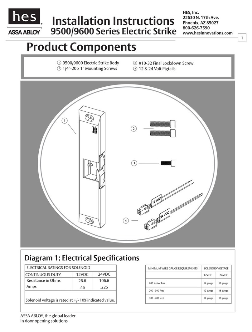
HES 9500 Series User manual

HES

HES 9500 Series User manual

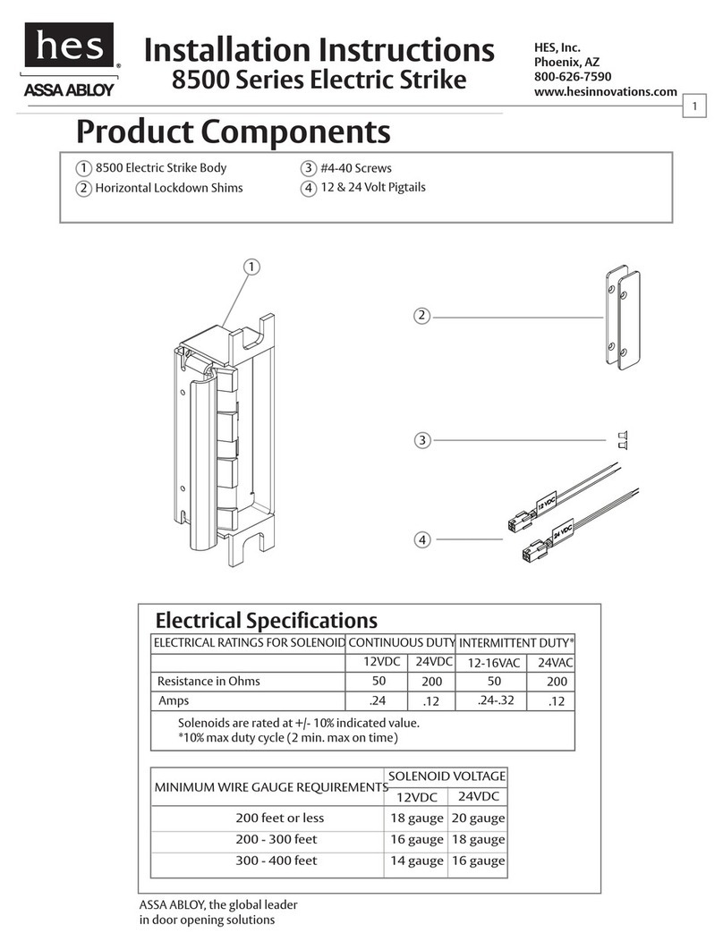
HES 8500 series User manual

HES

HES 8500 series User manual

HES ASSA ABLOY KS200 Manual

HES

HES ASSA ABLOY KS200 Manual

HES K100-620 Aperio Series User manual

HES

HES K100-620 Aperio Series User manual

Popular Lock manuals by other brands

COMPX B12 Dimensional drawing

COMPX

COMPX B12 Dimensional drawing

MARKS USA i-Qwik PROX Series Programming instruction manual

MARKS USA

MARKS USA i-Qwik PROX Series Programming instruction manual

COMPX Chicago CSA4107 instruction sheet

COMPX

COMPX Chicago CSA4107 instruction sheet

Next range Product guide

Next

Next range Product guide

Securikey REVO A quick start guide

Securikey

Securikey REVO A quick start guide

CODELOCKS CL5510 Getting started guide

CODELOCKS

CODELOCKS CL5510 Getting started guide

Securam ProLogic L22 operating instructions

Securam

Securam ProLogic L22 operating instructions

Assa Abloy Sargent PE80 Series installation instructions

Assa Abloy

Assa Abloy Sargent PE80 Series installation instructions

Roger SDC66 instruction manual

Roger

Roger SDC66 instruction manual

Falcon M Series Service manual

Falcon

Falcon M Series Service manual

COMPX CB095-195 instruction sheet

COMPX

COMPX CB095-195 instruction sheet

TYSON HaspLock Series installation instructions

TYSON

TYSON HaspLock Series installation instructions

Maco RAIL-SYSTEMS S&T-S Operating and maintenance instructions

Maco

Maco RAIL-SYSTEMS S&T-S Operating and maintenance instructions

Dorcas PROFAST installation manual

Dorcas

Dorcas PROFAST installation manual

Unipion CFR-170 user manual

Unipion

Unipion CFR-170 user manual

ADAMS RITE RITE Touch user guide

ADAMS RITE

ADAMS RITE RITE Touch user guide

Schlage B-Series installation instructions

Schlage

Schlage B-Series installation instructions

Phoenix SS0990E Series operating instructions

Phoenix

Phoenix SS0990E Series operating instructions

manuals.online logo
manuals.online logoBrands
  • About & Mission
  • Contact us
  • Privacy Policy
  • Terms and Conditions

Copyright 2025 Manuals.Online. All Rights Reserved.