HES ASSA ABLOY KS200 Manual

1 of 8
KS200 (Wiegand) & KS210 (OSDP)
Integrated Wired Server Cabinet Lock
Installation & Operating Instructions
Product Contents
A KS200/KS210 Lock Body
B Lock Interface Cable
C Rear Mounting Bracket
D Connectors (3)
E Screws (3) #8/32 x 1/4"
Pan Head Phillips
F Locking Cam
G Screw (1) #1/4-20 x 1/2"
Truss Head Phillips
H SFIC Cam & Spacer
I Plug-In External DPS Adapter
(Optional)
Recommended Tools
• Phillips #2 Screwdriver
• Cutting Wheel (As Required)
Recommended Accessories
• SFIC Mechanical Core and Keys
• KS-DPS Door Open/Closed Status
• CBL6-QC12 6 ft Door Interface Cable
• CBL12-QC12 12 ft System Side Interface Cable
• WT-2 Securitron Wiegand Test Box
Operation
To activate the KS200/KS210 integrated electronic access control
Server Cabinet Lock, present a known/valid credential to the card
reader. For emergency override, insert a valid key in to the SFIC (Small
Format Interchangeable Core) cylinder and rotate to the unlocked
position. Upon access granted, verify functionality by lifting and
rotating the handle to release the locking cam and open the door.
NOTE: The unit shall be powered by a UL294 listed power supply or access control
output with a power limited Class 2 output. The DC input feed to the device shall be
protected by 1A max rated over current protection provided at the installation site.
ASSA ABLOY recommends the use of Securitron and Life Safety Power power
management products for use with ASSA ABLOY branded electromechanical
and integrated electronic access control locking devices.
AB
Diagram 1: Product Components
CD
E
F
G
H
I
WARNING: This product can expose you to chemicals including lead, which is known to the state of California
to cause cancer and birth defects or other reproductive harm. For more information go to P65Warnings.ca.gov.
KS200
• Contains FCC ID:
JQ6-ICLASSBTM
• Contains IC ID:
2236B-ICLASSBTM
• WPC ID: ETA-SD-20210402373
KS210
• FCC ID: VC3-KS210
• IC ID: 7160A-KS210
• WPC ID: ETA-SD-20210402371

2 of 8
RF Frequency / Power
RADIO FREQUENCY (MHZ) MAX OUTPUT POWER (mW)
RFID 0.125 108
RFID 13.56 1375
Bluetooth LE
(KS210 Only) 2480 1
KS200 (Wiegand) Models
CARD TECHNOLOGY DESCRIPTION LF HF BLE
IPS Standard
IPE-XXXXX HID iCLASS Elite
PIV040 PIV 40-bit
PIV064 PIV 64-bit
PIV075 PIV 75-bit
PIV128 PIV 128-bit
PIV200 PIV 200-bit
KS210 (OSDP) Models
CARD TECHNOLOGY DESCRIPTION LF HF BLE
IPS Standard
IPE-XXXXX HID iCLASS Elite
PIV040 PIV 40-bit
PIV064 PIV 64-bit
PIV075 PIV 75-bit
PIV128 PIV 128-bit
PIV200 PIV 200-bit
LF (125 kHz Low Frequency)
CARD TECHNOLOGY KS200 KS210
HID Prox
Indala Prox
EM4102
AWID Prox
Kantech Prox
HF (13.56 MHz High Frequency)
CARD TECHNOLOGY KS200 KS210
ISO 14443 A/B
ISO 15693 – Felica™ (IDm)
HID iCLASS®Standard
HID iCLASS®Elite*
HID iCLASS®SE
HID iCLASS®SR
HID iCLASS®Seos
HID Security Identity Object (SIO)
PIV-II
MIFARE DESFire®0.6
MIFARE DESFire®EV1
MIFARE DESFire®EV2
Mobile Access*
CARD TECHNOLOGY KS200 KS210
HID NFC Mobile Access over HCE**
HID BLE Mobile Access**
Credential Formats Supported
Specifications
Designed For Use With Data Server
Cabinets (9U or larger).
• Lock Prep 150 x 25 mm
• Locking Type Cam Activated
• Mechanical Key Override SFIC
6 or 7-Pin (Sold Separately)
• Holding Force 350 lbs
Electrical
• Communication KS200 (Wiegand
TTL, SIAAC-01-1996) KS210 (OSDP
RS-485, SIA v2.2, IEC 60839-11-5)
• Card Technology HID multiCLASS SE
• HID Mobile Access NFC or BLE
• LED Visual Indicator Red / Green / Amber
• Voltage 12 to 24 VDC (-10% to +15% per UL294)
Environmental
• 32° to 122°F [-10° to 50°C]
• Weather Resistance Tested to meet IP54
(Not evaluated by UL)
• Indoor Use Only
Current Consumption
INPUT VOLTAGE 12 V DC 24 V DC
Standby Avg150 mA 40 mA
Max Avg2100 mA 75 mA
Peak3130 mA 130 mA
1 Standby AVG – RMS current draw without a
card in the RF field with both LEDs active.
2 Maximum AVG – RMS current draw during
continuous card reads, and both LEDs active.
3 Peak – Highest instantaneous current draw during
RF Communication, in-rush, or unlock cycles.
Certification & Listings
• UL294 Performance Levels
• Destructive Attack Level 1 (Attack Test)
• Line Security Level 1* (Line Security)
• Endurance Level 4 (250,000 Cycles)
• Standby Power Level 1* (No Standby)
*NOTE: Line Security, Destructive Attack and Standby
Power are determined by the end-product application.
Hereby, Hanchett Entry Systems, Inc (HES)
declares that the radio equipment type KS200/
KS210 are in compliance with Directive 2014/53/
EU. The full text of the EU declaration of conformity
is available at the following internal address:
assaabloyesh.com/en/tech-info/digital-asset-search
*NOTE: Contact Technical
Support at (800) 626-7590
for questions regarding
enabling HID iCLASS Elite,
BLE** or NFC over HCE.
**The product employs
provisions to be used with a
mobile credential that utilizes
a smart application that is
installed on a smart device
such as a phone. The mobile
credential utilized is required
to run on a smart device
that employs a compatible
operating system:
Apple iOS 11.0 or higher
Android v8.0 or higher
Furthermore, the reader utilizes
the Smart devices Bluetooth
functions. The units were
verified with Bluetooth version
4.2 or higher as well as HID
Mobile Access App (Version
3.76) or higher was verified as
an access control credential.

3 of 8
Diagram 2 Door Preparation
Diagram 3 Insert Lock Body
3A:
FRONT
3B:
BACK
Mounting
1. LOCATE the 6" x 1" [150 x 25 mm] lock
cutout on the door. Diagram 2.
2. INSERT the KS200/KS2100 Lock Body
(A) into the 6" x 1" [150 x 25 mm] cutout.
Make sure the unit bottom tabs grab
the back of the wall. Diagram 3.
3. ENSURE KS200/KS210 Lock Body (A)
is flush against the mounting surface
to ensure the tamper switch on the
back of the device is fully depressed
and operating correctly. Diagram 4.
4. CONNECT the female, 10-position
Hirose connector on the Lock Interface
Cable (B) to the back of the KS200/
KS210 Lock Body (A). Diagram 5.
NOTE: ENSURE that the Lock Interface
Cable (B) is not pinched or exposed prior to
attaching the Rear Mounting Bracket (C).
• (OPTIONAL) REMOVE the 4-Pin
and 8-Pin Molex Connectors from
the end of the Lock Interface
Cable (B) when the ElectroLynx
Interface Cables are NOT utilized.
• GO TO Optional Quick Connect Guide
(CONNECTIONS & WIRING) when
using ElectroLynx Interface Cables.
5. (OPTIONAL) CONNECT the Plug-In
RS-485 Auxiliary Output Adapter
Cable to extend control to other
compatible locking devices.
NOTE: Compatible with KS210
OSDP RS-485 models only.
6. (OPTIONAL) CONNECT the Plug-In
External DPS Adapter (I) Diagram 6
to extend the Tamper/Locked
State Monitoring to include other
EXTERNAL normally open switches
that can be wired in series to monitor
additional doors or panels.
NOTE: The DPS signals a secure state
(closed) when the handle is resting
in it the locked/latched position.
External DPS/Tamper rated for use up
to 100 mA at 30 VDC resistive load.
1"
[25.4mm]
6"
[150mm]
Diagram 4 Tamper Switch
NOTE: If the tamper switch is NOT fully
depressed, the Tamper/Locked State/DPS
contact will report as a non-secure status.
Tamper
Switch
Diagram 5 Connect Lock Interface Cable (B)
Integrated Handle
Locked State
Monitoring (SPST-NO)
Plug-In External
DPS Adaptor (3)
(Optional)
External Monitoring of
Doors/Panels with
Normally Open (SPST-NO)
Switches Sold Separately
Diagram 6 Connect (Optional) External DPS (I)
4 of 8
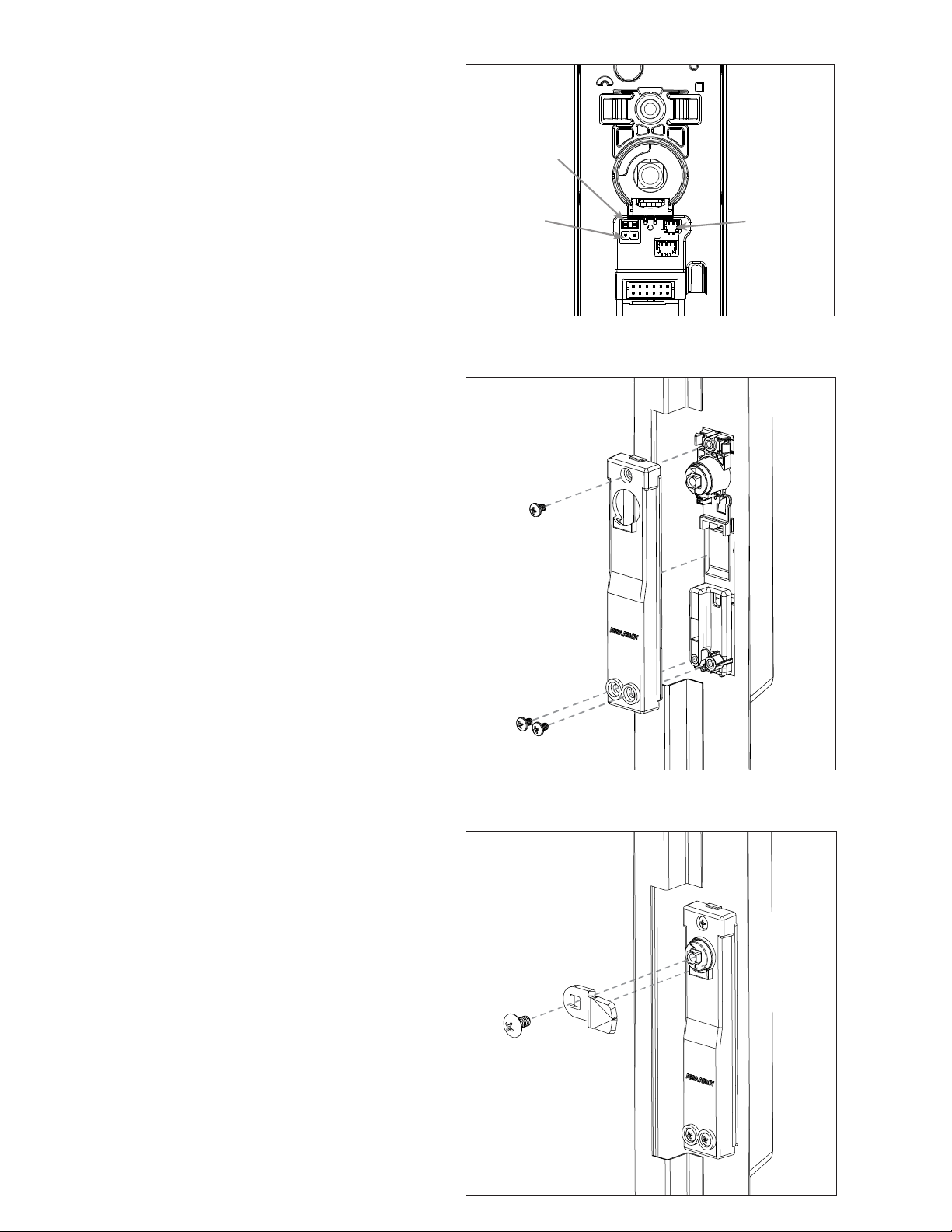
7. External DPS Adapter Activation. Diagram 7.
• REMOVE the jumper on the back of
the KS200/KS210 Lock Body (A).
• CONNECT the 2-Pin Plug-In External DPS Adapter
(I) to the back of the KS200/KS10 Lock Body.
• CONNECT additional normally-open switches
as shown to monitor door/panel status in series
with the integrated Locked State monitoring.
8. ATTACH Rear Mounting Bracket (C) to
KS200/KS210 Lock Body (A) using 3 Pan
Head Mounting Screws (E). Diagram 8.
9. INSTALL Locking Cam (F). Secure with
Truss Head Screw (G). Diagram 9.
Diagram 7 DPS Activation
Diagram 8 Attach Rear Mounting Bracket (C)
with Pan Head Screws (E)
Diagram 9 Install Locking Cam (F) with Truss Head Screw (G)
External
DPS
Jumper
Connect
adapter
RS-485
120 Ohm
termination
resistor
jumper

5 of 8
Cam Selection
NOTE: RE-USE existing cam when possible.
Installing SFIC Key Override
NOTE: SFIC blank is required if an SFIC cylinder is not used.
SFIC blank plastic core (SFIC-BC) sold separately.
1. Insert SFIC (H) cylinder and cam into
handle. Use spacer for 6-pin SFIC.
CAM
Depth
CAM
Length
Diagram 10 KS Cam Length Selection
Diagram 11 6 or 7-pin SFIC (H)
10a BACK 10b SIDE
7-PIN
6-PIN
PART NO. CAM CAM LENGTH CAM DEPTH
Included 38mm – 4 (standard) 1-1/2" [38mm] 1" [25.4mm]
KS-CAM38 38mm – 1 (optional) 1-1/2" [38mm] 1-1/10" [28mm]
KS-CAM45 45mm – 5 (optional) 1-3/4" [45mm] 7/10 " [18mm]

6 of 8
New 4-/8-Pin Molex
Products sold after January 2018
4-PIN
MOLEX
WIRE
COLOR FUNCTION SETTING
1Violet Lock Power COM (—)
2 Pink Tamper/Locked State/DPS NO (+)
3Gray Lock Power COM (+)
4Tan Tamper/Locked State/DPS COM (—)
8-PIN
MOLEX
WIRE
COLOR FUNCTION SETTING
1Black 12 VDC Reader (—)
2 White Wiegand Data / OSDP Data 1 / RS-485-A*
3N/A N/A Not Used
4N/A N/A Not Used
5Red 12 VDC Reader (+)
6Green Wiegand Data / OSDP Data 0 / RS-485-B*
7 Blue LED Red
8Yellow LED Green
*KS210 OSDP models only
Legacy 10-Pin Molex to 4-/8-Pin Molex
Products sold before December 2017
4-PIN
MOLEX
WIRE
COLOR FUNCTION SETTING
1Gray Lock Power COM (—)
2Yellow Tamper/Locked State/DPS NO (+)
3Violet Lock Power COM (+)
4 Blue Tamper/Locked State/DPS COM (—)
8-PIN
MOLEX
WIRE
COLOR FUNCTION SETTING
1Black 12 VDC Reader (—)
2 White Wiegand Data / OSDP Data 1 / RS-485-A*
3N/A N/A Not Used
4N/A N/A Not Used
5Red 12 VDC Reader (+)
6Green Wiegand Data / OSDP Data 0 / RS-485-B*
7Orange LED Red
8Brown LED Green
*KS210 OSDP models only
Cable & Wire Connections
EAC Integrated Wired: KS200/KS210 Server Cabinet Locks, ElectroLynx Wire Color/Function Assignments
Connections & Wiring
Diagram 12 Server Cabinet Wiring Example
Cabinet Door
6 ft Door Interface Cable
(CBL6-QC12)
CBL6-QC12, 6 ft Door
Interface Cable
Lock Interface Cable
CBL12-QC12, 12 ft System
Side Interface Cable to EAC
Panel Connection
4-Pin Molex
Connector
PIN WIRE COLOR
1Violet
2Pink
3Gray
4Tan
8-Pin Molex
Connector
PIN WIRE COLOR
1Black
2White
3N/A
4N/A
5Red
6Green
7Blue
8Yellow
4
2
1
12
7
83
6
5
ATTENTION: Installation wiring for the product and wiring methods shall be in accordance with the National
Electrical Code (NEC), ANSI/NFPA 70. Observe precautions for handling electrostatic sensitive devices.
Optional Accessories (Sold Separately)
CBL6-QC12 6 foot x 12-Wire Door Interface
Cable (ElectroLynx connectors on both ends).
Designed for use with the CBL12-QC12.
CBL12-QC12 12 foot x 12-Wire System Side
Interface Cable (ElectroLynx connectors on one
end, pins and loose connectors on opposite
end). Designed for used with the CBL6-QC12.
NOTE: Pins 3 and 4 are
not used on the 8-Pin
Molex connector.

7 of 8
Optional Quick Connect
Guide (Sold Separately)
1. CONNECT the Lock Side Interface Cable to the
optional 6 ft Door Interface Cable (CBL6-QC12).
NOTE: SEE Server Cabinet Wiring Example, Diagram 12.
2. CONNECT the Door Interface Cable to
the additional optional 12 ft System Side
Interface Cable (CBL12-QC12).
NOTE: 18 ft TOTAL wire run when BOTH
optional interface cables are utilized.
3. RUN the 12 ft System Side Interface
Cable, as required.
4. ATTACH the included 4-Pin and 8-Pin Female Molex
Connectors to the bare wire side of the System
Side Interface Cable to extend the interface cable
for installations that require longer than 18 ft.
System Side Connections
NOTE: Installation wiring for the product and
wiring methods shall be in accordance with the
National Electrical Code (NEC), ANSI/NFPA 70.
5. CONNECT the bare wires as required to
the 3rd party wiring as needed to connect
to Electronic Access Control System.
6. ENSURE the following power cabling
guidelines are followed:
WIRE AWG SUPPLY VOLTAGE MAX WIRE RUN (FT)*
20 AWG 12 758
24 5305
22 AWG 12 477
24 3336
24 AWG 12 300
24 2098
*Round trip loss. V = 2*I*R*xft → xft = V / (2*I*R)
Round Trip Loss
Application Notes
1. Data 0 and Data 1 wires for Wiegand may be reused
for OSDP. However, standard Wiegand cable may
not meet RS485 twisted pair recommendations for
maximum data transmission speed and distance.
2. For OSDP cable lengths greater than 200 ft
[61 m] or EMI interference, install 120
Ohm termination resistor jumper on
the KS210 as shown in Diagram 7.
Additional OSDP
Information
Available at:
assaabloyesh.com/en/tech-info/digital-asset-search/
1. Understanding OSDP Implementations
(HID/Mercury FAQ)
2. How OSDP Is Revolutionizing Access
Control Systems (Webinar)
3. Why Upgrade to OSDP (Infographic)
4. Demystifying OSDP (eBook)
Testing & Commissioning
PRIOR to applying power.
1. VERIFY that the SFIC (Small Format
Interchangeable Core) cylinder has been
installed. If so, verify mechanical actuation of
locking cam allowing for emergency override.
2. VERIFY that the handle has been returned to the
secure/locked state; ensure the door is closed
with the locking cam engaging the cabinet
and the handle full seated in the lock body.
3. APPLY power to the system to verify
electronic functionality.
4. VERIFY that the LED is illuminated
with the correct RED or GREEN color
displaying while in the secure state.
5. PRESENT a known/valid credential to the RFID target
on the face of reader portion (as shown) of the lock
to confirm acknowledgment of access granted.
»VERIFY that you hear an audible beep when
a credential is presented to the reader.
»VERIFY that you see the visual LED
indicator temporarily change state.
»VERIFY that you hear the motor actuate
from a lock to unlock state.
6. LIFT the handle and ROTATE in the direction
of the door hinges to open the cabinet.
»VERIFY that the Tamper/Locked State/DPS
has changed to a non-secure state.
7. RETURN the handle to the secure/locked
state; ensure the door is closed with the
locking cam engaging the cabinet and the
handle full seated in the lock body.
»VERIFY that the Tamper/Locked State/
DPS has returned to the secure state.

8 of 8
Printed in the U.S.A.
Patent pending and/or patent www.assaabloydss.com/patents
Copyright © 2021-2022, Hanchett Entry Systems, Inc., an ASSA ABLOY Group company.
All rights reserved. Reproduction in whole or in part without the express written
permission of Hanchett Entry Systems, Inc. is prohibited. 3080006.023_1
Warranty
For information on warranty coverage and replacement options, please visit hesinnovations.com/warranty
Regulatory
FCC
This device complies with part 15 of the FCC
Rules. Operation is subject to the following two
conditions: (1) This device may not cause harmful
interference, and (2) this device must accept any
interference received, including interference
that may cause undesired operation.
CAUTION: Any changes or modifications to this device
not explicitly approved by the manufacturer could
void your authority to operate this equipment.
This equipment has been tested and found to
comply with the limits for a Class B digital device,
pursuant to part 15 of the FCC Rules. These limits are
designed to provide reasonable protection against
harmful interference in a residential installation. This
equipment generates, uses and can radiate radio
frequency energy and, if not installed and used in
accordance with the instructions, may cause harmful
interference to radio communications. However, there
is no guarantee that interference will not occur in a
particular installation. If this equipment does cause
harmful interference to radio or television reception,
which can be determined by turning the equipment
off and on, the user is encouraged to try to correct the
interference by one or more of the following measures:
• Reorient or relocate the receiving antenna.
• Increase the separation between
the equipment and receiver.
• Connect the equipment into an outlet on a circuit
different from that to which the receiver is connected.
• Consult the dealer or an experienced
radio/TV technician for help.
Model KS200 Contains FCC ID
• JQ6-ICLASSBTM
Model KS200 Contains IC ID
• 2236B-ICLASSBTM
Canada Radio Certification
This device complies with Industry Canada license-
exempt RSS standard(s). Operation is subject to
the following two conditions: (1) this device may
not cause interference, and (2) this device must
accept any interference, including interference that
may cause undesired operation of the device.
Le présent appareil est conforme aux CNR d’Industrie
Canada applicables aux appareils radio exempts
de licence. L’exploitation est autorisée aux deux
conditions suivantes : (1) l’appareil ne doit pas
produire de brouillage, et (2) l’utilisateur de l’appareil
doit accepter tout brouillage radioélectrique
subi, même si le brouillage est susceptible
d’en compromettre le fonctionnement.
CE Marking
Hanchett Entry Systems, Inc. (HES) hereby declares
that these proximity readers are in compliance
with the essential requirements and other
relevant provisions of Directive 2014/53/EU.
Por el presente, HES, Inc. declara que estos lectores de
proximidad cumplen con los requisites esenciales y otras
disposiciones relevantes de la Directiva 2014/53/EU.
HES, Inc. déclare par la présente que ces
lecteurs à proximité sont conformes aux
exigences essentielles et aux autres stipulations
pertinentes de la Directive 2014/53/EU.
HES, Inc., por meio deste, declara que estes leitores de
proximidade estão em conformidade com as exigências
essenciais e outras condições da diretiva 2014/53/EU.
HES, Inc. bestätigt hiermit, dass die Leser die
wesentlichen Anforderungen und anderen relevanten
Bestimmungen der Richtlinie 2014/53/EU erfüllen.
HES, Inc. dichiara che i lettori di prossimità sono
conformi ai requisiti essenziali e ad altre misure rilevanti
come previsto dalla Direttiva europea 2014/53/EU.
techsupport.hes@assaabloy.com
800 626 7590 | hesinnovations.com
10027 S. 51st Street, Ste. 102
Phoenix, AZ 85044 USA
This manual suits for next models
1
Table of contents
Other HES Lock manuals


Popular Lock manuals by other brands


InteTrend
InteTrend Smart Deadbolt Lock user manual

Yale
Yale Assure Lock YRD216 Installation and programming instructions

ENFORCER
ENFORCER SD-72081-6MQ manual

Schlage
Schlage FE575 Door Preparation Instructions

Gianni Industries
Gianni Industries PBT-900 Series Specification sheet

DOM
DOM RONIS CoverK Assembly