Lockly DUO User manual

INTERCONNECTED EDITION
INSTALLATION
GUIDE
DUO™

Go to LOCKLY.com/pages/installation to watch a
video version of this installation guide.
Download the BILT app in the Apple or Google Play
store for step-by-step interactive 3-D walk-through
installation instructions.
OR
Reference installation parts overview foldout on back page
Welcome!
This guide will walk you through step-by-step how
to install and get your LOCKLY Duo™up and running.
Installation generally takes less than 30 minutes. If you
have any questions please reference our online support
at: LOCKLY.com/support or call (669) 500-8835 for help.
3
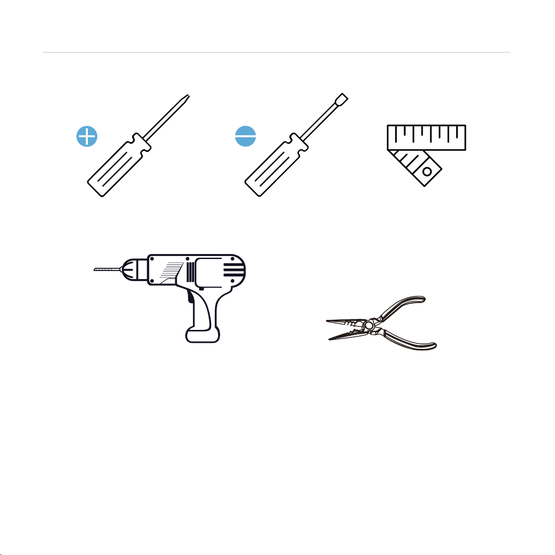
Phillips Screwdriver
To complete the installation you will need:
Flathead Screwdriver Tape measure or ruler
Preparation
Pliers
Optional
Screwdriver with drill bits
Drilling maybe required to install this lock. If you are installing your lock on a brand new
door, a drill is required if there are no holes prepared for lock installation. Use provided
template to bore holes on door.

4
Preparation
Measure and confirm your door is
between 1 ⅜" - 2"
(
35mm - 50mm).
Measure and confirm the hole in
the door is 2 ⅛" (54mm).
Measure and confirm that the
backset is between 2 ⅜" (60mm)
to 2 ¾" (70mm).
Measure and confirm that hole in
the door edge is 1"(25mm).
Remove existing door hardware, latch or deadbolts before installing the new lock.
Use provided template to bore new holes if needed.
1
2
3
4
Measure and confirm that distance
between front door holes is
4”(101.6mm) or 5.5”(139.7mm)
5
1- 3/8"—2"
(35mm—50mm)
2-3/8"(60mm)
or
2-3/4"(70mm)
2-1/8"
54mm
54mm
1"
25mm
4"(101.6mm)
or
5.5"(139.7mm)
2-1/8"
1"
25mm

5
INSTALLING THE LOCKSET
Step 1
1
2 ⅜"(60mm) 2 ¾"(70mm)
(a)
II. Hold the metal plate (c) and
twist the deadbolt body (d)
clockwise till it snaps to 2-3/8"
III. To return to default status,
while the deadbolt (b) is
extended, hold the metal
plate (c) and twist the dead
bolt body (d) counter-clock-
wise till it snaps to 2-3/4"
I. Push the crank (a) to extend
the deadbolt (b)
Deadbolt Adjustment
Latchbolt Adjustment
b
cd
dc
a
Push the shaft (a) to adjust the
lockset to 2-3/8"(60mm) or
2-3/4"(70mm).
2-3/8"
(60mm)
2-3/4"
(70mm)
G
G
G
G
Measure the distance between center of front door hole to the edge of your door hole
to determine the backset. Adjust latchbolt Fand deadbolt Jaccording to the backset
of your door.
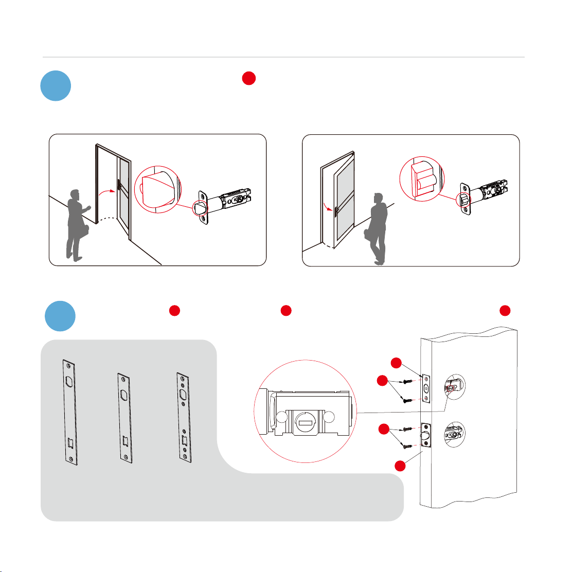
6
INSTALLING THE LOCKSET
Step 1
continued
J
G
G
F
Install deadbolt J (top) and latchbolt F(bottom) to door and secure with screws G.
Retract deadbolt and make sure bore hole is horizontally positioned.
Optional: Stainless steel mortise slot cover, 4" or 5.5" Face Plates available. To purchase,
PGA018
PGA019 PGA019S
For mortise slot
5.5” 4”
3
After adjusting the latchbolt F, determine the orientation of the latchbolt.
Determine the orientation of latchbolt. Facing the door exterior, install the
latchbolt according to the opening direction of your door.
In-swing Door
OR
Out-swing Door
2
7
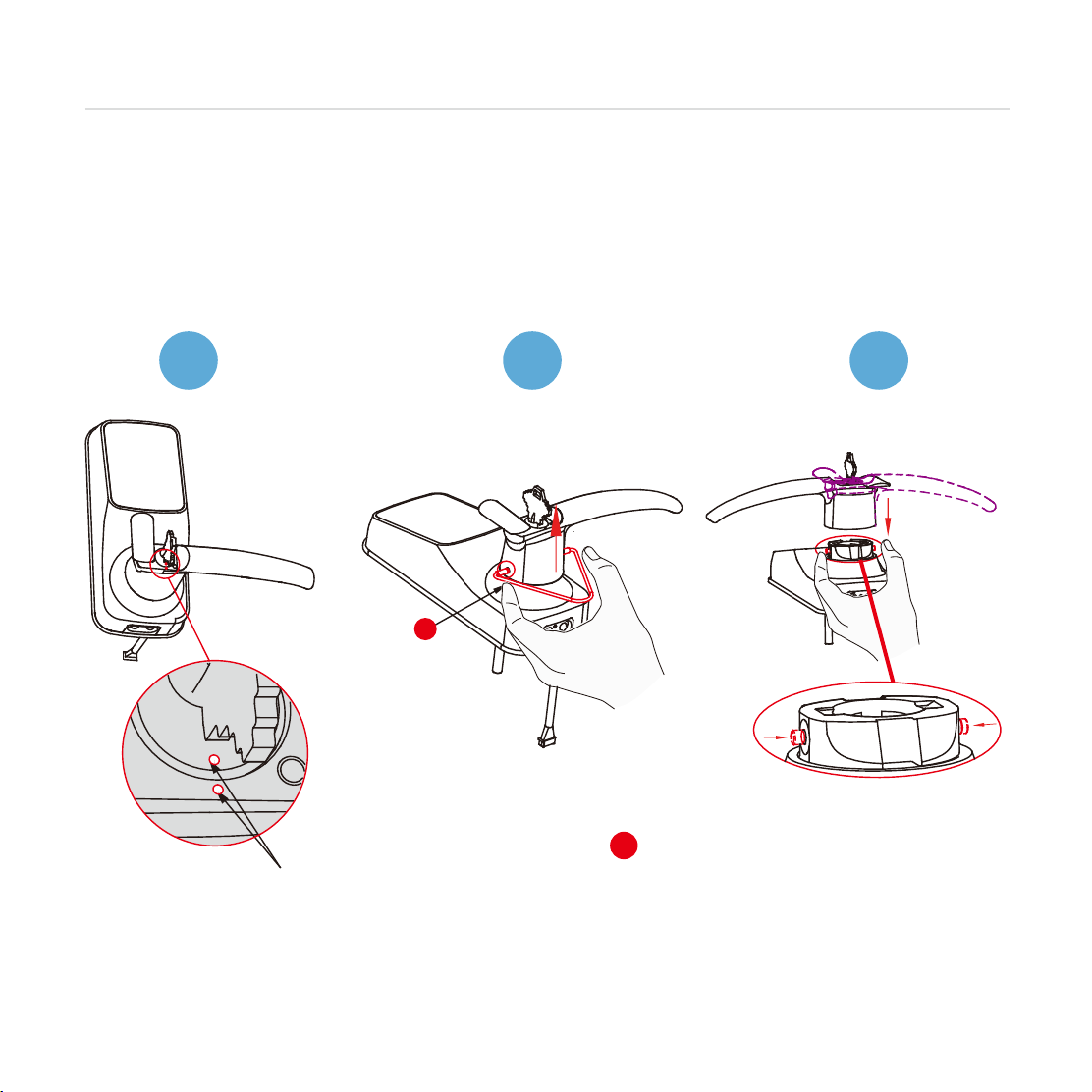
CHANGING HANDLE FOR RIGHT OR LEFT SWING DOORS
Step 2
R
The lock ships set for right swing doors. Skip Step 2 if your door is a right swing door.
See steps below to change door handle orientation for a left swing door.
Determine right swing or left swing door
While facing the door from the inside, if hinges are on the right side you have the right swinging
door. If hinges on the left side you have a left swinging door.
Changing the Exterior Handle Orientation
(Right handle)
Insert key and rotate lock
face so that the two white
dots align as shown.
With both dots aligned, use the
provided clamping tool Rto
push in the two metal pins at the
base of the lock handle located
at the 3 o’clock and 9 o’clock
positions. Once depressed,
remove the handle.
Rotate the handle 180o
to the other side of the lock.
Using your fingers, press the
two pins located on the left
and right side of the the lock
to insert the handle back
onto the lock.
12 3

8
CHANGING HANDLE FOR RIGHT OR LEFT SWING DOORS
Step 2
continued
Check that your handle works
smoothly by moving it in both
the up and down direction.
Once you determine that
the handle is secure and
operating properly turn
key back to its horizontal
position and remove.
456
Remove the screw
position on point "R"
789
Confirm that your installation was
complete by checking if the pins
are flush against the handle, and
has popped out. Adjust the handle
accordingly to make sure the pins
are fully decompressed and sitting
flush against the surface.
Insert the removed screw
from point "R" screw
tightly to point "L".
Use a flathead screwdriver
to press the middle marker
and move to point "L".
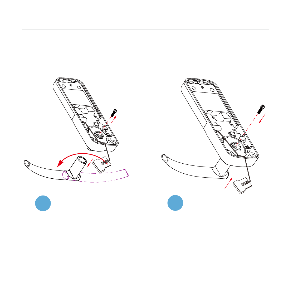
CHANGING HANDLE FOR RIGHT OR LEFT SWING DOORS
Step 2
continued
Remove handle retaining screw by
turning counter-clockwise. Remove
handle and rotate 180° as shown.
Changing the Interior Handle Orientation
Return handle retaining screw and
secure by turning opposite direction
(clockwise).
12
9
Other manuals for DUO
1
Table of contents
Other Lockly Lock manuals

Lockly
Lockly LUX Compact User manual

Lockly
Lockly SECURE User manual

Lockly
Lockly Vision PGD798SN User manual

Lockly
Lockly SECURE User manual

Lockly
Lockly DUO User manual

Lockly
Lockly VISION ELITE User manual

Lockly
Lockly VISION ELITE User manual

Lockly
Lockly SECURE User manual

Lockly
Lockly Vision User manual


