hestan GFDSR241 Quick guide

Outdoor Beer Dispensing Equipment
Installation and Instruction
Manual
24” SINGLE FAUCET BEER DISPENSER SOLID DOOR RIGHT HINGE
24” SINGLE FAUCET BEER DISPENSER SOLID DOOR LEFT HINGE
24” DOUBLE FAUCET BEER DISPENSER SOLID DOOR RIGHT HINGE
GFDSR241
GFDSL241
24” DOUBLE FAUCET BEER DISPENSER SOLID DOOR LEFT HINGE
GFDSL242
GFDSR242
P/N 011028 rev A
Form. No. Z2425

HESTAN RESIDENTIAL INSTALLATION MANUAL FOR BEER DISPENSING EQUIPMENT
2hestanoutdoor.com
CONGRATULATIONS
Congratulations on your purchase of a Hestan high
quality residential beer dispenser. Hestan has proudly partnered,
to our exact specifications, with a quality manufacturer for
its beer dispensing systems. The manufacturer has been producing
beer dispensing systems for over 50 years for bars, restaurants,
stadiums, arenas and large venues around the world. That
same technology is used in each and every residential beer
dispenser. Assuring you’ll pour fresh, cold beer as the brewery
intended it to be enjoyed.
All Hestan products are built with commercial grade
stainless steel, providing you with the beauty and durability
for a lifetime of use. This installation guide will show you
how to properly install the dispensing equipment on your
Hestan Beer Dispenser.
We dedicate considerable time to ensure that our products
provide the highest level of customer satisfaction. If,
however, service is required, call Hestan at 888-905-7463.
For your own protection, never return merchandise for
credit without our approval.
We thank you again for selecting a high quality Hestan Beer
Dispenser. Cheers!
C
US
IMPORTANT!
The installation of the actual beer
dispenser cabinet should happen prior
to installing the dispensing equipment.
Refer to the Installation Manual that
accompanied the Beer Dispenser for step-
by-step installation of the cabinet.
Keep CO2 cylinder away from
heat. Rupture disc vents at 122°F
maximum.
Allow only properly trained and
experienced personnel to handle
high pressure gas.
DANGER
WARNING
Do not drop or throw regulator or
CO2 cylinder.
DANGER
Do not apply oil to the regulator!
WARNING
INSTALLATION OF DISPENSING EQUIPMENT
Open the tapping kit box and become familiar with
its components. If the dispensing head is going to be
mounted on a counter top directly above the refrigerated
cabinet, have the counter top pre-drilled using the
supplied template on page 9. Make sure that the access
hole in the refrigerated cabinet is in line with the counter
top holes. Remove any obstructions from the access hole
of the refrigerator.
Follow instructions on pages 3 through 8 to properly
install the tapping equipment on your Hestan unit.
NOTE:Wash tapping devices thoroughly. Flush
beer and faucet lines, as well as the tapping device
(keg coupler) with fresh water.

3
hestanoutdoor.com
HESTAN RESIDENTIAL INSTALLATION MANUAL FOR BEER DISPENSING EQUIPMENT
INSTALLATION OF DISPENSING EQUIPMENT
Open the tapping kit box and become familiar with its
components. The instructions on pages 4 through 8
will demonstrate how to properly install the tapping
equipment on your new Hestan Beer Dispenser.
Dispensing Head
Faucet Lead
Apply silicone to
Air Distributor
Flange Sleeve
All hose connections
use worm-drive
hose clamps (view
enlarged to verify)
Distributor is only on
multiple keg units,
each keg is connected
to a valve on the air
distributor. Single keg
is connected directly to
the regulator.
Keg
Keg Coupler
Beer Connection
shown are to clearly illustrate proper connection methods
only.
NOTE: Image does not accurately reflect positions of the
different elements within the unit. Postions and hose lengths

HESTAN RESIDENTIAL INSTALLATION MANUAL FOR BEER DISPENSING EQUIPMENT
4hestanoutdoor.com
Locate the dispensing head , black beer line(s), and
hose clamp(s). Slide one end of each beer line onto the
stainless steel tubes which protrude out the bottom of
the dispensing head and clamp tight.
Remove transit tape with a utility knife around the hole
in the top of the unit from both inside and outside of
the cabinet. Gently punch out foam w/screwdriver and
remove. Insert the beer line(s) through the hole in the
counter top. Move head aside and bead silicone around
perimeter of hole, and then position the head back
in place. Fasten using the 4 chrome screws included
complete the seal.
1.
2.
Use the 3/8” -thick foam pad included in the tapping kit
and roll into a cylinder. From inside the cabinet, insert
the foam tube up through the hole in the counter top
head. Mark, then cut away any excess foam.
3.
with the dispensing head. Wipe off excess silicone to
until it is firmly against the insulation in the dispensing
5
hestanoutdoor.com
HESTAN RESIDENTIAL INSTALLATION MANUAL FOR BEER DISPENSING EQUIPMENT
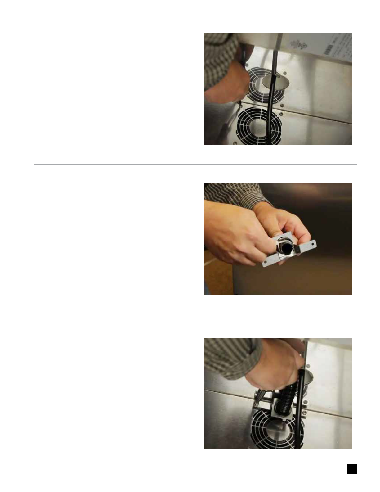
Insert end of the snorkel up into the tower and screw
air scoop mounting bracket into vacated holes above
the fan.
6.
Install the Air Scoop Kit. Start by removing the upper set
of screws located above the fan on the back wall of the
cabinet.
Assemble components from the kit as follows – Insert
black snap bushing into air scoop mounting bracket,
then insert one end of the air snorkel through the snap
bushing. A zip tie can be inserted behind the mounting
bracket to keep the tube in place.
4.
5.
This manual suits for next models
3
Table of contents
Other hestan Kitchen Appliance manuals


