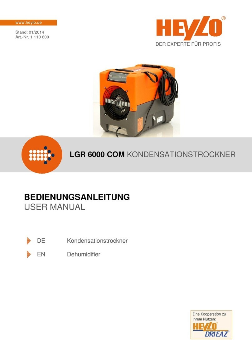
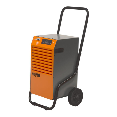
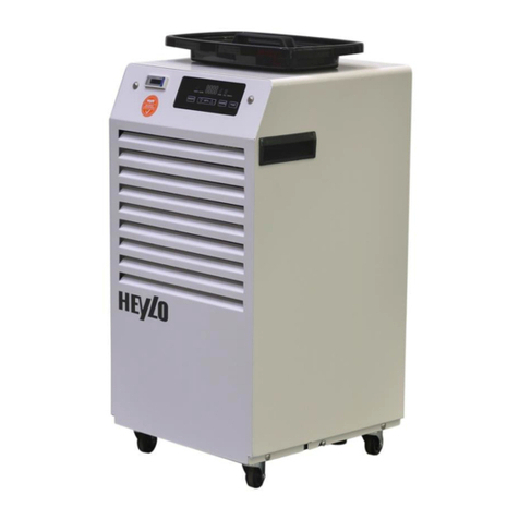
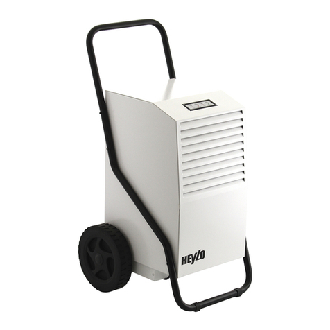
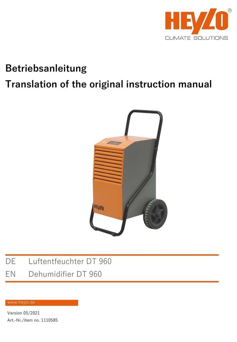
Heylo DT 550 User manual

DT 950 ENTFEUCHTER
www.heylo.de
Stand: 01/2020
Art.-Nr. 1 110 603
BEDIENUNGSANLEITUNG
USER MANUAL
DE Entfeuchter
EN Dehumidifier
DER EXPERTE FÜR PROFIS

2
DE
EG-Konformitätserklärung
Gemäß der EG-Richtlinie 89/392/EEC in der geänderten Fassung 91/368/EEC,
93/44/EEC und 93/68/EEC (Maschinenverordnung)
Für Gerätebaureihe : Elektrogeräte –Kondensationstrockner/Entfeuchter
Typ: DT 550, DT 650, DT 750, DT 850, DT 950
HEYLO GmbH, Im Finigen 9, 28832 Achim, erklärt, dass die genannten Maschinen, wenn sie gemäß
Bedienungsanleitung und nach den anerkannten Regeln der Technik installiert, gewartet und gebraucht werden,
den grundlegenden Sicherheits- und Gesundheitsanforderungen der Richtlinie „Maschinen“, sowie folgenden
Bestimmungen und Normen entsprechen.
Zutreffende EG-Richtlinien:
EN 600335-1:2002 + A2:2006 Sicherheit für Maschinen (Maschinenverordnung)
EN 60335-2-40:2003 + A11:2004, Sicherheit für Maschinen (Maschinenverordnung)
A12:2005, A1:2006 (spezielle Richtlinie für elektrische Pumpen, Klimaanlagen und
Kondensationstrockner)
EN 61000-6-3:2007 Elektromagnetische Verträglichkeit (EMC). , Part 6-3
EN 61000-6-1:2007 Elektromagnetische Verträglichkeit (EMC). , Part 6-1
EN 61000-6-2:2006 Elektromagnetische Verträglichkeit (EMC).
EN 61000-6-3:2008 Elektromagnetische Verträglichkeit (EMC).
EN 300 220-3 v1.1.1 Elektromagnetische Verträglichkeit (ERM).
EN301 489-3 v1.4.1 Elektromagnetische Verträglichkeit (ERC).
Diese Produkte erfüllen die Anforderungen nach den Bestimmungen der Richtlinie über die elektromagnetische
Verträglichkeit 2004/108/EG und ihrer Änderungen, der Richtlinien 2006/95/EG und der Niederspannungs-
Richtlinie und deren Änderungen.
Die Geräte sind typgeprüft nach DIN VDE 0700 Teil 1 und Teil 30 EN 60 335-1 und
EN 60 335-2-30 und tragen ein CE-Zeichen.
Achim, 06.01.2014 …………………….…….……………..
Dr. Thomas Wittleder
- Geschäftsführer -
----------------------------------------------------------------------------------------------------------------------------------------
Inhaltsverzeichnis
1. Sicherheitshinweise............................................................................................................................. 3
2. Arbeitsweise und Entfeuchtungsleistung............................................................................................. 3
3. Aufstellen des Kondensationstrockners.............................................................................................. 4
4. Inbetriebnahme / Bedienung des Kondensationstrockners................................................................. 4
4.1 Inbetriebnahme.................................................................................................................................. 4
4.2 Bedienung ......................................................................................................................................... 4
4.3. Was tun, wenn der Luftentfeuchter nicht einschaltet oder nicht entfeuchtet?.................................. 5
5. Anschluss Kondensatablauf................................................................................................................ 6
6. Periodische Wartung........................................................................................................................... 6
7. Technische Daten................................................................................................................................ 7
8. Fehlersuche......................................................................................................................................... 8
9. Ersatzteilliste ....................................................................................................................................... 9
10. Schaltplan........................................................................................................................................ 11

3
DE
1. Sicherheitshinweise
ACHTUNG: Vor Inbetriebnahme unbedingt lesen!
Bitte beachten Sie sorgfältig die Hinweise in der Bedienungsanleitung. Bei Nichtbeachtung erlischt der
Gewährleistungsanspruch. Für Schäden bzw. Folgeschäden die daraus entstehen, übernimmt der
Hersteller keine Haftung.
Kinder fernhalten: Kinder nicht mit dem oder in der Nähe des Geräts spielen lassen.
Elektrischer Anschluss: HEYLO Bautrockner sind für den Betrieb mit 230V/50Hz ausgelegt. Nur mit
Schukostecker verwenden! Genutzte Steckdosen müssen geerdet sein, bzw. mit einem
Fehlerstromschutzschalter in der Hausinstallation abgesichert sein.
Stromkabel vor Beschädigung schützen: Das Gerät niemals mit beschädigtem Stromkabel
benutzen. Wenn das Stromkabel beschädigt ist, muss es durch ein Kabel derselben Art und
Bemessung ersetzt werden.
Verlängerungskabel: Nur zugelassene Verlängerungskabel benutzen!
Mit Sorgfalt behandeln: Das Gerät nicht fallen lassen oder werfen, da es sonst zu Beschädigungen
von Bauteilen oder der Verdrahtung kommen kann.
Auf einer festen Fläche arbeiten: Das Gerät immer auf einer festen, ebenen Fläche aufstellen.
Während des Transports sichern: Bei Transport in Fahrzeugen Gerät gegen Rutschen sichern.
Trocken halten: Das Gerät darf nicht in Pfützen oder stehendem Wasser betrieben werden. Nicht im
Freien aufbewahren oder betreiben. Wenn die elektrische Verdrahtung oder Teile des Geräts nass
werden, ist das Gerät vor der Wiederbenutzung gründlich zu trocken.
Luftöffnungen frei halten: Die Luftein- und auslässe nicht abdecken oder blockieren.
Filter sauber halten: Immer einen sauberen Luftfilter verwenden. Den Filter nicht verstopfen lassen,
da sich der Bautrockner sonst überhitzen kann. Darauf achten, dass kein Öl, Fett oder andere
Verschmutzungen in den Bautrockner gesaugt werden.
Reparaturen des Gerätes: Bitte lassen Sie Reparaturarbeiten nur von Servicepartnern der Firma
HEYLO durchführen. Informationen über das HEYLO Servicecenter oder zugelassene
Servicetechniker erhalten Sie telefonisch, per Fax oder E-Mail:
2. Arbeitsweise und Entfeuchtungsleistung
Der DT 950 ist ein Kondensationstrockner. Die Entfeuchtungsfunktion entsteht, indem die feuchte
Raumluft über die kalte Verdampfereinheit geblasen wird. Die Feuchtigkeit kondensiert auf der kalten
Oberfläche und tropft ab. Das entstandene Kondensat wird in den Kondensattank geleitet oder über
die Kondensatförderpumpe bzw. den Ablassschlauch abgeführt. Die jetzt wärmere und trocknere Luft
kehrt in den Raum zurück und nimmt dort wieder Wasserdampf auf.
Wenn der Kondensationstrockner bei einer Zimmertemperatur unter ca. 20°C arbeitet, bildet sich
normalerweise Reif auf der Verdunsterschlange. Stellt die Elektronik Eistemperatur auf dem
Verdampfer fest, löst sie automatisch den Abtauzyklus aus. Während dieser Zeit läuft eine
beträchtliche Wassermenge vom Verdampfer in den Kondensattank. Sobald das Eis am Verdampfer
abgetaut ist, wird der normale Betrieb wieder aufgenommen. Da die Abtauung per Heißgas erfolgt,
dauert der Abtauzyklus nur ein paar Minuten.
Die Menge des Wassers, welches vom Gerät entfernt wird, hängt bei allen Kondensationstrocknern
von der Luftfeuchtigkeit und Lufttemperatur ab. Die Leistung des Bautrockners ist möglichst daran zu
messen, wie schnell die Luftfeuchtigkeit sinkt und nicht daran, wie viel Wasser ihr entzogen wird. Die
genaue Luftfeuchtigkeit können sie mit einem Thermo-Hygrometer messen.
4
DE
3. Aufstellen des Kondensationstrockners
Der Kondensationstrockner sollte in einem geschlossenen Raum betrieben werden, um die beste
Leistung zu erzielen. Alle Öffnungen zu anderen Teilen des Gebäudes, wie Fenster und Türen,
schließen, damit sich feuchte Luft nicht mit der Luft in den zu trocknenden Bereichen vermischt. Türen
möglichst wenig öffnen und schließen. Dadurch wird eine sogenannte geschlossene Trockenkammer
gebildet. Es sollten so viele Geräte eingesetzt werden, dass ein dreifacher Luftwechsel erzielt wird.
Innerhalb der Trockenkammer sollte die Luft frei zirkulieren können. Interne Türen öffnen und
Luftgebläse einsetzen, um eine gute Luftzirkulation in allen Bereichen zu erzielen.
Den Bautrockner so aufstellen, dass der Luftfluss durch Einlass und Auslass nicht eingeschränkt ist.
Nicht in der Nähe von losem Material, wie z. B. Gardinen, aufstellen.
Normalerweise ist der Kondensationstrockner in der Mitte des Raumes aufzustellen. Um eine
bestimmte Stelle zu trocknen, ist der Kondensationstrockner so aufzustellen, dass die abgegebene
Luft auf den nassen Bereich gerichtet ist und die warme, trockene Luft darüber fließt. Die Öffnung
sollte mindestens einen Meter von der Wand entfernt sein.
Der HEYLO-Kondensationstrockner erwärmt die Luft, der er die Feuchtigkeit entzieht. In kleineren
Räumen kann dadurch die Temperatur beträchtlich ansteigen. Zimmertemperaturen zwischen 20° und
27°C bieten allgemein gute Bedingungen für das Trocknen. Die Zimmertemperatur darf 38°C nicht
überschreiten und 1°C nicht unterschreiten, da sonst der Kondensationstrockner nicht mehr arbeitet.
(siehe Fehlermeldungen Punkt 7)
4. Inbetriebnahme / Bedienung des Kondensationstrockners
4.1 Inbetriebnahme
Der Luftentfeuchter der Serie DRYTECH wird einzeln verpackt angeliefert, die Verpackung sollte wie
folgt entfernt werden:
Halten Sie den Karton gerade, Verpackung NICHT auf den Kopf stellen (die Schrift muss gerade
gelesen werden können). Durchschneiden Sie nun mit einer Schere oder ähnlichem die Bänder, die
den Boden an der Verpackung festhalten, und ziehen Sie die Verpackung nach oben ab. Entfernen
Sie nun den oberen Transportschutz aus Polystyrol. Anschließend heben Sie das Gerät vom unteren
Transportschutz herunter und stellen es auf den Boden. Als letztes entfernen Sie bitte die Plastikfolie.
Der Bügelgriff zum Transport des Gerätes ist bei Anlieferung lose beigelegt. Bitte entfernen Sie die in
den beiden Rohren befindlichen Schrauben, stecken den Bügel auf die am Gerät montierten
Gegenstücke des Bügels und verschrauben die Rohre mittels der herausgedrehten Schrauben.
4.2 Bedienung
Nach dem einstecken des Netzsteckers in eine geeignete Schutzkontaktsteckdose leuchtet die rote
Kontrollleuchte „POWER” (B). Sollte die Kontrollleuchte „WORKING” ausgeschaltet sein, dreht man
den auf der Rückseite befindlichen Hygrostaten (BILD2) auf eine höhere Luftfeuchteeinstellung oder
auf CONT für Kontinuierlichen Betrieb.sich im Schaltfeld befindlichen Drehknopf, im Uhrzeigersinn, bis
die Leuchte einschaltet. Auch die Leuchte für „Pause” schaltet ein und nach ungefähr fünf Minuten
beginnt der Entfeuchter zu arbeiten.

5
DE
Das Kontrollfeld (1) befindet sich in der oberen Abdeckung des Gerätes, und mit vier
Kontrollleuchten versehen. Den Regulierdrehknopf (2) zum Ein- und Ausschalten und zum
Einstellen des Feuchtegrades, finden Sie auf der Rückseite des Entfeuchters.
(1)
Unter jeder Kontrollleuchte ist in Kurzform die Funktion beschrieben.
Grünes Licht „FULL” (D) (VOLL): schaltet dieses Licht ein, so kommt das Gerät zum Stillstand, da der
Behälter mit dem Kondensationswasser voll ist.
Rotes Licht „POWER“ (B) (SPANNUNG): zeigt an, dass der Stecker an den Stromkreis
angeschlossen ist und das Gerät mit Strom versorgt.
Rotes Licht „WORKING” (C) (BETRIEB): es schaltet ein, wenn der Feuchtigkeitsmesser den Betrieb
des Luftentfeuchters freigibt; sind die Leuchten „DEFROST” und „FULL” ausgeschaltet, ist der
Kompressor in Betrieb.
Rotes Licht „DEFROST” (A) (Pause) zeigt an, dass der Kompressor einschaltbereit ist; das erfolgt bei
jeder Inbetriebnahme und während des Abtauens, das zyklisch erfolgt.
(2)
Mit dem Regulierdrehknopf (2) reguliert man die gewünschte Feuchtigkeit im Raum. Mit
ansteigender Zahl erhöht sich der Entfeuchtungsgrad der Luft. Dies bedeutet, dass bei Zahl 1ein
Entfeuchtungsgrad von ca. 95% erreicht wird (immer in Abhängigkeit von den Umgebungs-
bedingungen!), bei Zahl 5können ca. 35% r. f. erreicht werden und bei Stellung Cont. (Continious
= ständig) entfeuchtet das Gerät ohne Abschaltung durch den Hygrostaten.
Die Angabe „OFF = AUS” bedeutet, dass der Kontakt des Feuchtigkeitsmessers offen ist, und das
Gerät somit nicht funktioniert. Achtung, bei angeschlossenem Netzstecker stehen die elektrischen
Bauteile im Gerät weiterhin unter Spannung.
4.3. Was tun, wenn der Luftentfeuchter nicht einschaltet oder nicht entfeuchtet?
Zuerst sollte man sich vergewissern, dass die rote Kontrollleuchte “POWER” eingeschaltet ist. Damit
ist sichergestellt, dass das Gerät mit Strom versorgt ist, andernfalls kontrolliert man, ob der Stecker
richtig eingesteckt ist und ob die Steckdose auch wirklich mit Strom versorgt ist.
Vergewissern sie sich, dass die grüne Kontrollleuchte „FULL” aus ist. Ist das nicht der Fall,
kontrolliert man, ob der Behälter voll ist, oder die Schaltwippe auf dem der Tank steht durch
Fremdkörper blockiert ist.
A
C
B
D

6
DE
Kontrollieren Sie, ob die rote Kontrollleuchte “WORKING” leuchtet, was bedeutet, dass durch den
Feuchtigkeitsmesser (Hygrostat BILD2) der Betrieb gefordert wird. Schaltet das Gerät nach einer
Pause, weil eventuell die gewünschte Luftfeuchtigkeit erreicht wurde oder der Kanister entleert wurde,
wieder ein, leuchtet außer den zentralen roten Lampen auch das rote Licht für “DEFROST” auf. In
dieser Abtauphase, die ungefähr 5 Minuten dauert, funktioniert nur der Ventilator, wobei der
Kompressor stillsteht. Dieser Zyklus wiederholt sich etwa alle 45 Minuten, um das Abtauen des
Verdampfers zu ermöglichen. Sollte das Gerät normal funktionieren (die zwei mittleren roten Lichter
sind eingeschaltet) aber kein Wasser oder nur spärliches Wasser abgeben, ist zu kontrollieren, ob die
relative Raumluftfeuchtigkeit weniger als 40-45% beträgt
Leuchtet die Lampe (DEFROST) ist die Abtauphase in Betrieb. Die Heißgasabtauung funktioniert
folgendermaßen: ca. alle 45 Min. stoppt der Kompressor für 6 Min., der Ventilator verbleibt in Betrieb.
Nach Ablauf der Wartezeit schaltet der Kompressor wieder zu.
Durch einen Temperaturfühler wird das Absinken der Temperatur durch Vereisung unter 0 °C
registriert und über die Elektronikplatine wird ein Magnetventil im Kältekreis umgeschaltet, so dass der
Weg des Kältemittels mit dem Heißgas nun über den Verdampfer führt und damit das Eis
abgeschmolzen wird. Mit ansteigender Temperatur am Verdampfer wird das Abtauverfahren beendet
und das Ventil schaltet in seine Ursprungslage zurück. Während des Abtauvorgangs ist der Ventilator
abgeschaltet.
5. Anschluss Kondensatablauf
Die Luftentfeuchter der Serie DRYTECH können direkt an ein flexibles Abflussrohr angeschlossen
werden. In diesem Fall entfernt man den Kanister, um den Schlauch anzuschließen. Für den
Anschluss benutzt man möglichst einen Silikon-Schlauch mit einer Muffe von 3/4”. Der Schlauch kann
durch ein im Geräteboden befindliches Loch nach außen geführt werden.
6. Periodische Wartung
WARNUNG: Wartungsarbeiten sind bei abgeschaltetem Gerät, d. h. mit gezogenem Netzstecker,
auszuführen.
Alle 4 Wochen oder nach jedem Trocknungsjob: - Filter wechseln
- Gerät reinigen
- Tank und Abschaltung prüfen
Alle 6 Monate: - Reinigung Verdampfer /Verflüssiger
Alle 12 Monate: - Komplette Reinigung und Wartung
- BGVA3 Prüfung
Die Ersatz-Filter und Reinigungsmittel können bei HEYLO als Ersatzteile bezogen werden,
bitte sprechen Sie uns an!

7
DE
7. Technische Daten
Modell
DT 950
Elektr. Anschluss
230 V /50 Hz
Luftleistung
650 m/h³
Leistungsaufnahme max.
0,95 kW
Stromaufnahme max.
5 A
Entfeuchtungsleistung (30oC 80% r.F.)
52 l/24h
Entfeuchtungsleistung max.
62 l/24h
Trocknerleistung Fläche (h=250/20°C)
130 m²
Lautstärke bei 3 m Abstand
51 dB(A)
Abmessungen (Höhe / Breite / Tiefe)
900 / 520 / 460 mm
Gewicht
49 kg
Kapazität Wasserbehälter
13 l
Menge Kältemittel Typ R 407c
700 g
Kompressor Art
Rollkolben
Verdampfer Art
Röhrenverdampfer
Entfrostung
Heißgas elektron.
Einsatztemperatur
1–38oC
Relative Luftfeuchtebereich
35 –99%
Kondensierte Feuchtigkeit in 24 Stunden bei unterschiedlichen Bedingungen:
Typ
Temperaturen und Feuchtigkeit im Raum
DT
20o-60%
20o-80%
25o-60%
25o-80%
27o-65%
30o-80%
32o-80%
950
20
28
25
35
28
52
62

8
DE
8. Fehlersuche
PROBLEM
URSACHE
Ausf.
Lösung
Gerät startet nicht
Kein Spannung am Gerät
(Powerleuchte B leuchtet
nicht)
Hygrostat nicht eingeschaltet
(Workingleuchte C leuchtet
nicht)
B
B
Gerät an der Steckdose anschließen;
überprüfen, ob diese Strom führt.
Schalter B einschalten
Kompressor startet nicht
Das Gerät benötigt 5 Minuten
vor einem Neustart.
Überlastung verhindert Start.
Fehlerhafter oder gebrochener
Leiter
Defekte Steuerung
Kompressor läuft nicht
Gerät befindet sich in der
Abtauung
B
B
HS
HS
HS
Gerät abschalten, 5 Min. warten, dann
starten.
Zimmertemperatur auf unter 38°C senken.
Gebrochenen/losen Leiter ersetzen oder
reparieren.
Steuerung/ Kompressor prüfen
Wenden Sie sich an Ihren Händler oder
an das HEYLO-Servicecenter.
Ca. 15min warten
(im Display steht „entfrosten“)
Gebläserad läuft nicht
Gebläse blockiert
Lockerer oder gebrochener
Leiter
Fehlerhafter Gebläsemotor
B
HS
HS
Blockierung entfernen
Gebrochenen Leiter ersetzen
Gebläsemotor auswechseln
Bautrockner arbeitet,
aber Raum trocknet nicht
Nicht genug Zeit zum
Austrocknen
Mangelnde Luftbewegung
Zu großer Zufluss von
(Außen-) Luft
B
B
B
Mehr Zeit zum Austrocknen nehmen
Luftbewegung mit HEYLO Turbotrocknern
erhöhen
Luftfluss in den zu trocknenden Bereichen
reduzieren.
Eis oder Feuchtigkeit nur
An einem Teil der Kühl-
schlangen
System möglicherweise
undicht
Geringe Füllung des Systems
HS
HS
Undichte Stelle mit einem Gasspürgerät
suchen.
System reparieren und nachfüllen.
Keine Feuchtigkeit oder
Eis an den Kühlschlangen
Temperatur oder
Luftfeuchtigkeit zu niedrig
System möglicherweise
undicht
Kältesystem beschädigt
Kompressor läuft nicht
B
HS
HS
HS
Umgebungsklima mit HEYLO MMS plus
messen
Undichte Stelle mit einem Gasspürgerät
suchen
Kompressor prüfen
Wenden Sie sich an Ihren Händler oder
an das HEYLO-Servicecenter
Gerät ständig auf
DEFROST
Zimmertemperatur zu niedrig
Defekter Regler
B
HS
Zimmertemperatur erhöhen.
Verdampferfühler auswechseln
Gerät entfrostet nicht)
Defekte Abtaueinrichtung
Defekter Regler
HS
HS
Magnetventil oder Spule tauschen
Verdampferfühler tauschen
Gerät sammelt wenig
Wasser
Raum zu trocknen
Zimmertemperatur zu niedrig
Luftfluss durch Gerät
eingeschränkt
B
B
B
Luftfeuchtigkeit mit einem Hygrometer
bestimmen.
Zimmertemperatur erhöhen.
Luftfluss erhöhen, Filter und Schlangen
säubern.
Gerät pumpt nicht ab (nur
bei
Pumpe auf eventuelle Fehler
überprüfen
Pumpe defekt
Kondensatschlauch verstopft
oder abgeknickt
HS
HS
B
Pumpe reinigen und falls erforderlich
defekte Teile austauschen
Pumpe austauschen
Kondensatschlauch reinigen
Ausführender: B –Benutzer, AST - autorisierten Servicetechniker
Wenden Sie sich für Ersatzteile und Service an Ihren Händler vor Ort oder an die HEYLO
Kundendienstabteilung.

9
DE
9. Ersatzteilliste

10
DE
Ersatzteile
Pos.
HEYLO Art.-Nr.
Bezeichnung
1+2
DT950001
Bügelgriff, komplett
3
DT950003
Anschlusskabel
4
DT950004
Luftfilterhalter
5
DT850031
Betriebsstundenzähler
6
DT850003
Drehknopf Hygrostat
7
DT950007
Filterrahmen
8
DT950008
Luftfilter
9
DT850039
Schalteinheit
11
DT850005
Bedienpanelhalterung
12
DT950012
Halterung Steuerelektronik
13
DT950013
Energiezähler (KW/h), optional
14
DT950014
Frontabdeckung
15
DT950015
Abdeckblech
16
DT950016
Verdampferhalter oben
17
DT950017
Verdampfer
18
DT950018
Verflüssiger
19
DT850041
Steuerelektronik
20
DT950020
Lüfterflügel
21
DT950021
Ventilatormotor
22
DT950022
Verdampferhalter, unten
23
DT850029
Magnetventil
24
DT950024
Trockner mit Kapillar
25
DT950025
Halter Ventilatomotor
26
DT950026
Abtau-Thermostat
27
DT950027
Wasserbehälter
29
DT950029
Rad
30
DT950030
Kompressor
31
DT950031
Fuß, einzeln
32
DT850024
Mikroschalter
33
DT950033
Feder Tankwippe
36
DT950036
Achse
37
DT950037
Tankwippe
45
DT950045
Motorschutz Verdichter

11
DE
10. Schaltplan

12
EN
EC Declaration of Conformity
In conformity with EC Directive 89/392/EEC in the modified version 91/368/EEC,
93/44/EEC and 93/68/EEC (machine ordinance)
For unit series: Electrical appliances - Dehumidifier
Type: DT 550, DT 650, DT 750, DT 850, DT 950
HEYLO GmbH of Im Finigen 9, D-28832 Achim, Germany, declares that, if they are fitted, maintained and used in
conformity with the operating instructions and the generally accepted engineering standards, the machines
mentioned are in keeping with the fundamental safety and health requirements of the “Machine Ordinance” as
well as with the regulations and standards mentioned hereinafter.
Applicable EC directives:
EN 600335-1:2002 + A2:2006 Safety of machines (machine ordinance)
EN 60335-2-40:2003 + A11:2004, Safety of machines (machine ordinance)
A12:2005, A1:2006 (special directive for electric pumps, air conditioning systems and
dehumidifier)
EN 61000-6-3:2007 Electro-Magnetic Compatibility (EMC), part 6-3
EN 61000-6-1:2007 Electro-Magnetic Compatibility (EMC), part 6-1
EN 61000-6-2:2006 Electro-Magnetic Compatibility (EMC).
EN 61000-6-3:2008 Electro-Magnetic Compatibility (EMC).
EN 300 220-3 v1.1.1 Electro-Magnetic Compatibility (EMC).
EN301 489-3 v1.4.1 Electro-Magnetic Compatibility (EMC).
These products meet the requirements in conformity with the Directive on Electromagnetic
Compatibility 2004/108/EC and its modifications, the Directive 2006/95/EC and the Low-Voltage
Directive and its modifications.
The devices are type-tested in conformity with German standard DIN VDE 0700,
part 1 and part 30 EN 60335-1 and
EN 60335-2-30 and bear a CE mark.
Achim, 6th January 2014 …………………….…….……………..
Dr Thomas Wittleder
- Managing Director -
----------------------------------------------------------------------------------------------------------------------------------------
Table of contents
(1) Safety guidelines.............................................................................................................................. 13
(2) Mode of operation and demoisting performance ............................................................................. 13
(3) Setting up the dehumidifier .............................................................................................................. 14
(4) Putting into operation / operation of the dehumidifier ..................................................................... 14
(4.1) Putting into operation.................................................................................................................... 14
(4.2) Operation ...................................................................................................................................... 14
(4.3) What to do if the air humidifier does not switch on or if it does not dehumidify?.......................... 15
(5) Connection to condensate discharge............................................................................................... 16
(6) Periodic maintenance....................................................................................................................... 16
(7) Technical data.................................................................................................................................. 16
(8) Fault finding...................................................................................................................................... 17
(9) List of spare parts............................................................................................................................. 18
(10) Wiring diagram............................................................................................................................... 20

13
EN
(1) Safety guidelines
CAUTION: Read carefully before starting up!
Please observe the notes in the operating instructions carefully. In case of non-observation, the
warranty claims will become void. The manufacturer shall not be liable for any damage and/or
consequential damage resulting.
Keep away from children: Do not allow children to play with or in the vicinity of the device.
Electric connection: HEYLO dehumidifier have been designed for operation on 230 V / 50 Hz. Use
shock-proof plugs only. The sockets have to be earthed or protected by residual current circuit-
breakers in the house installation.
Protect the power cable against damage: Never use the unit with damaged power cable. If the
power cable has been damaged, it has to be replaced by a cable of the same type and dimension.
Extension cable: Use approved extension cables only!
Handle with care: Do not drop or throw the unit as this may cause damage to the unit or wiring.
Operate on solid surface: Always set up the unit on a solid and plane surface.
Secure during transport: When transporting devices in vehicles, secure against slipping.
Keep dry: The unit must not be operated in puddles or in standing water. Do not store or operate
outdoors. If the electric wires or parts of the unit get wet, the unit has to be thoroughly dried before re-
using.
Keep the air openings free: Do not cover or block the air inlets and outlets.
Keep the filter clean: Always use a clean air filter. Do not permit the filter to clog as the dehumidifier
may overheat otherwise. Make sure that no oil, grease or other dirt is drawin into the dehumidifier.
Repair of the device: Please have the repairing work carried out by service partners of HEYLO
Company only. For information on the HEYLO Service Centre or approved service technicians, please
refer to telephone book, facsimile directory or E-mail:
(2) Mode of operation and demoisting performance
DT 950 is a dehumidifier. The dehumidifying function is produced by blowing moist ambient air across
the cold evaporation unit. The humidity condenses on the cold surface and drips down. The
condensate produced is passed into the condensation tank and can be removed by the optional
condensate delivery pump or drain hose. The now warmer and dryer air returns into the room and
takes up water vapour again.
If the dehumidifier operates at a room temperature of below about 20 deg. C, hoar frost normally forms
on the humidifier. If the electronic system finds ice temperature on the evaporator, the defrosting cycle
is released automatically. During this perior, a considerable amount of water passes from the
evaporator into the condensate tank. As soon as the ice of the evaporator has thawed, the normal
operation is started again. As defrosting is carried out by hot gas, the defrosting cycle will take only a
few minutes.
The amount of water which is removed by the unit depends on the air humidity and the air
temperature. The performance of the dehumidifier can be measured by how fast the air humidity
decreases and not by how much water has been removed. The precise air humidity can be measured
by means of a thermo-hygrometer.

14
EN
(3) Setting up the dehumidifier
The dehumidifier should be operated in a closed room in order to achieve its best performance. Close
all openings to other parts of the building, such as windows and doors, so that the humid air cannot
mix with the air in the areas to be dried. Open and close doors as far as possible. A so-called closed
drying chamber is produced. A number of units should be used to permit a triple air change.
Within the drying chamber, the air should be free to circulate. Open doors inside and employ air
blowers in order to achieve a good air circulation in all parts.
Set up the construction dryer in such a way that the air flow is not restricted by the inlet and outlet. Do
not set up near loose material, such as curtains.
Normally the dehumidifier is set up in the middle of the room. In order to dry a certain point, the
dehumidifier has to be set up in such a way that the air is directed on to the wet area and the hot, dry
air passes over. The opening should be at least one meter away from the wall.
HEYLO dehumidifier heat the air which is drawn from the humidity. In smaller room, the temperature
may increase considerably. Room temperatures of between 20 deg. and 27 deg. C offer good drying
conditions as a rule. The room temperature should not exceed 38 deg. C and should not go below 1
deg. C as otherwise the dehumidifier no longer operates (cf. chapter (7).
(4) Putting into operation / operation of the dehumidifier
(4.1) Putting into operation
Air dehumidifiers of the DRYTECH series are delivered individually wrapped. The packaging should
be removed as follows:
Keep the cardboard straight. Do NOT turn the packaging upside down (it must be possible to read the
writing). Using scissors or a similar tool, cut through the straps holding the bottom at the packaging
and pull off the packaging upwards. Now remove the polystyrene transport protection. Then lift off the
device from the lower transport protection and put it on the floor. Finally, please remove the plastic
film.
The device is delivered with a bow-type handle for transporting it. Please remove the screws which are
within the two pipes, put the clip on the counterparts mounted on the device and screw together the
pipes by means of the loosened screws.
(4.2) Operation
After putting the mains plug into a suitable protective contact socket, the red indicator lamp „POWER”
(B) will light up. Should the indicator lamp „WORKING” be switched off, turn the humidity switch
located on the back side (IMAGE 2) to a higher air humidity position or the rotary knob located in the
control panel to CONT position for continuous operation until the lamp lights up. The indicator lamp
„Pause” will also light up, and after about 5 minutes, the dehumidifier will start operation.
The control panel (1) is in the upper cover of the device and equipped with four indicator lamps. The
setting knob (2) for switching the device on and off and for setting the degree of moisture is located on
the back side of the dehumidifier.

15
EN
(1)
Under each indicator lamp, the function is described in brief.
Green light „FULL” (D): if this lamp lights up, the device will stop, because the container holding the
condensation water is full.
Red light „POWER“ (B): indicates that the plug is connected to the electric circuit supplying the device
with power.
Red light „WORKING” (C): will light up if the humidity meter enables operation of the air dehumidifier.
If the lamps „DEFROST” and „FULL” are switched off, the compressor is being in operation.
Red light „DEFROST” (A) indicates that the compressor is ready for operation; this takes place with
each commissioning and during defrosting taking place as a cycle.
(2)
The desired humidity within a room is regulated using the setting knob (2). The degree of air
moisture removal will rise with increasing number. This means that in position 1, a humidity
removal degree of approx. 95% (always depending on ambient conditions!) is achieved, whereas in
position 5, approx. 35% room humidity can be reached, and in position Cont., the device will
dehumidify without being switched off by the hygrostat.
Position „OFF” means that the contact of the humidity meter is open and thus the device does not
work. Attention! With the mains plug being connected, electric components of the device will keep
being under voltage.
(4.3) What to do if the air humidifier does not switch on or if it does not dehumidify?
First make sure that the red indicator lamp “POWER” is switched on. That way it is ensured that power
is supplied to the device. Otherwise it can be checked whether the plug is correctly inserted and
whether the socket is really supplied with power.
Check to see that the indicator lamp „FULL” is not lit. If this is not the case, check if the container
is full or the rocker switch on the container is not blocked by foreign matter.
Check if the red indicator lamp “WORKING” lights up meaning that operation is required by the
humidity meter (Hygrostat IMAGE 2). If the device switches on again after a break, possibly because
the desired air humidity has been reached or the container has been emptied, the red lamp
“DEFROST” will light up apart from the central red lamps. In this defrost phase, which will last about 5
minutes, only the fan will function, with the compressor being at a standstill. This cycle will repeat
about every 45 minutes in order to enable the evaporator to defrost. Should the device function in a
normal way (with the two lamps in the middle being switched on), but delivering no a scarce water, it
must be checked whether the relative air humidity is less than 40-45%.
A
C
B
D

16
EN
If the DEFROST lamp illuminates, the defrost phase is in operation. Hot gas defrosting works as
follows: the compressors stops approx. every 45 minutes for 6 minutes, while the fan keeps being in
operation. When the waiting period is over, the compressor will switch on again.
A temperature drop below 0°C due to icing is recorded by means of a temperature sensor, and a
solenoid valve in the cooling circuit is switched via the electronic board so that the refrigerant with the
hot gas is now led via the evaporator thus melting the ice. With increasing temperature of the
evaporator, the defrosting process is finished, with the valve switching back to its original position. The
fan is switched off during the defrosting process.
(5) Connection to condensate discharge
Air humidifiers of the DRYTECH range can be connected directly to a flexible discharge pipe. In this
case, the container is removed in order to connect a hose. A silicon hose with a 3/4” sleeve is used for
connection, if possible. The hose can be guided through a hole which is in the bottom of the device.
(6) Periodic maintenance
WARNING: Maintenance work shall have to be carried out with the unit switched off, i.e. with mains
plug removed.
Every 4 weeks or after each drying job: - change filters
- clean device
- check container and switch-off
Every 6 months: - clean evaporator/condensor
Every 12 months: - complete cleaning and maintenance
- BGVA3 test
Replacement filters and cleaning agents can be purchased from HEYLO as spare parts,
please contact us!
(7) Technical data
Model
DT 950
Electric Connection
230 V / 50 Hz
Air performance
650 m/h³
Power input, max.
0.95 kW
Current consumption
5 A
Dehumidification performance (30 deg.
C / 80 per cent r.h.)
52 l/24h
Dehumidification performance max.
62 l/24h
Dryer performance surface (h=250/20°C)
130 m²
Noise at 3 m distance
51 dB(A)
Dimensions (height x width x depth)
900 / 520 / 460 mm
Weight
49 kg
Water reservoir capacity
13 l
Amount of refrigerant type R 407C
700 g
Type of compressor
Rotary piston
Evaporator type
Tube evaporator
Defrosting
Hot gas, electronic
Operating temperature
1–38oC
Relative air humidity
35 –99%
Condensed humidity in 24 hours at different conditions:
Type
Temperatures and humidity in room
DT
20o-60%
20o-80%
25o-60%
25o-80%
27o-65%
30o-80%
32o-80%
950
20
28
25
35
28
52
62

17
EN
(8) Fault finding
PROBLEM
CAUSE
Version
Solution
Device does not start up
No voltage on the device
(indicator lamp Power B does
not illuminate)
Hygrostat not switched on
(indicator lamp Working C
does not illuminate)
B
B
Connect device to power socket; check it
carries current.
Turn on switch B
Compressor does not start
up.
The device requires 5 minutes
prior to a new start.
Overload prevents start.
Faulty or broken conductor
Defective control
Compressor not operating
Device is defrosting
B
B
HS
HS
HS
Switch off device, wait 5 minutes, then
start it.
Lower room temperature to below 38°C.
Replace or repair broken/loose
conductor.
Check control/compressor
Please contact your dealer or the
HEYLO service centre.
Wait 15 minutes
(display shows “defrosting”)
Impeller is not operational.
Fan is blocked.
Loose or broken conductor
Defective fan motor
B
HS
HS
Remove blockage.
Replace broken conductor
Replace fan motor
Dehumidifier operating,
but room does not dry
Not enough time for drying
Insufficient air movement
Too large inflow of (outside)
air
B
B
B
Allow more time for drying
Increase air movement using HEYLO
turbo dryers
Reduce air flow into the areas to be
dried.
Ice or humidity only
on part of cooling coils
System possibly leaking
Little filling of system
HS
HS
Look for leakage using a gas detector.
Repair and top up system.
No humidity or ice on the
cooling coils
Temperature or air humidity
too low
System possibly leaking
Cooling system damaged
Compressor not operating
B
HS
HS
HS
Measure ambient atmosphere using
HEYLO MMS plus
Look for leakage using a gas detector
Check compressor
Please contact your dealer or the
HEYLO service centre
Device always on
DEFROST
Room temperature too low
Faulty controller
B
HS
Increase room temperature.
Replace evaporator sensor
Device does not defrost)
Defective defrosting device
Faulty controller
HS
HS
Replace solenoid valve or coil
Replace evaporator sensor
Device collects little water
Room too dry
Room temperature too low
Air flow trough device limited
B
B
B
Determine air humidity using a
hygrometer.
Increase room temperature.
Increase air flow, clean filter(s) and
cooling coils.
Device not pumping off
(check with
pump only for potential error
Pump faulty
Condensate hose clogged or
snapped off
HS
HS
B
Clean pump and, if necessary, replace
defective parts
Replace pump
Clean condensate hose
Performer: B - user, AST - authorised service technician
Ask your local dealer for spare parts or get in touch with HEYLO service department.

18
EN
(9) List of spare parts

19
EN
List of spare parts
Item
HEYLO Art. No.
Designation
1+2
DT950001
Bow-type handle, complete
3
DT950003
Connection cable
4
DT950004
Air filter bracket
5
DT850031
Operating hours counter
6
DT850003
Hygrostat rotary knob
7
DT950007
Filter frame
8
DT950008
Air filter
9
DT850039
Switching unit
11
DT850005
Control panel bracket
12
DT950012
Control electronics bracket
13
DT950013
Energy counter (kW/h), optional
14
DT950014
Front cover
15
DT950015
Cover plate
16
DT950016
Evaporator bracket, top
17
DT950017
Evaporator
18
DT950018
Condenser
19
DT850041
Control electronics
20
DT950020
Fan blade
21
DT950021
Fan motor
22
DT950022
Evaporator bracket, bottom
23
DT850029
Solenoid valve
24
DT950024
Dryer with capillaries
25
DT950025
Fan motor bracket
26
DT950026
Defrosting thermostat
27
DT950027
Water container
29
DT950029
Wheel
30
DT950030
Compressor
31
DT950031
Base, single
32
DT850024
Micro switch
33
DT950033
Spring, container rocker
36
DT950036
Axle
37
DT950037
Container rocker
45
DT950045
Compressor motor protection

20
EN
(10) Wiring diagram
Other manuals for DT 550
2
This manual suits for next models
4
Table of contents
Languages:
Other Heylo Dehumidifier manuals

Heylo
Heylo BT 60 Quick start guide

Heylo
Heylo KT 20 User manual

Heylo
Heylo DT 850 User manual

Heylo
Heylo LGR 6000 COM User manual

Heylo
Heylo DT 550 User manual

Heylo
Heylo DT 760 Quick start guide

Heylo
Heylo DT 960 Quick start guide

Heylo
Heylo DT 750 User manual

Heylo
Heylo DT 550 User manual

Heylo
Heylo DT 860 Quick start guide