HF HF-BL200A User manual

HF-BL100-CU Low Energy Bluetooh(BLE 4.1)Module User Manual
Shanghai High Flying Electronics Technology Co., Ltd www.hi-flying.com - 1 -
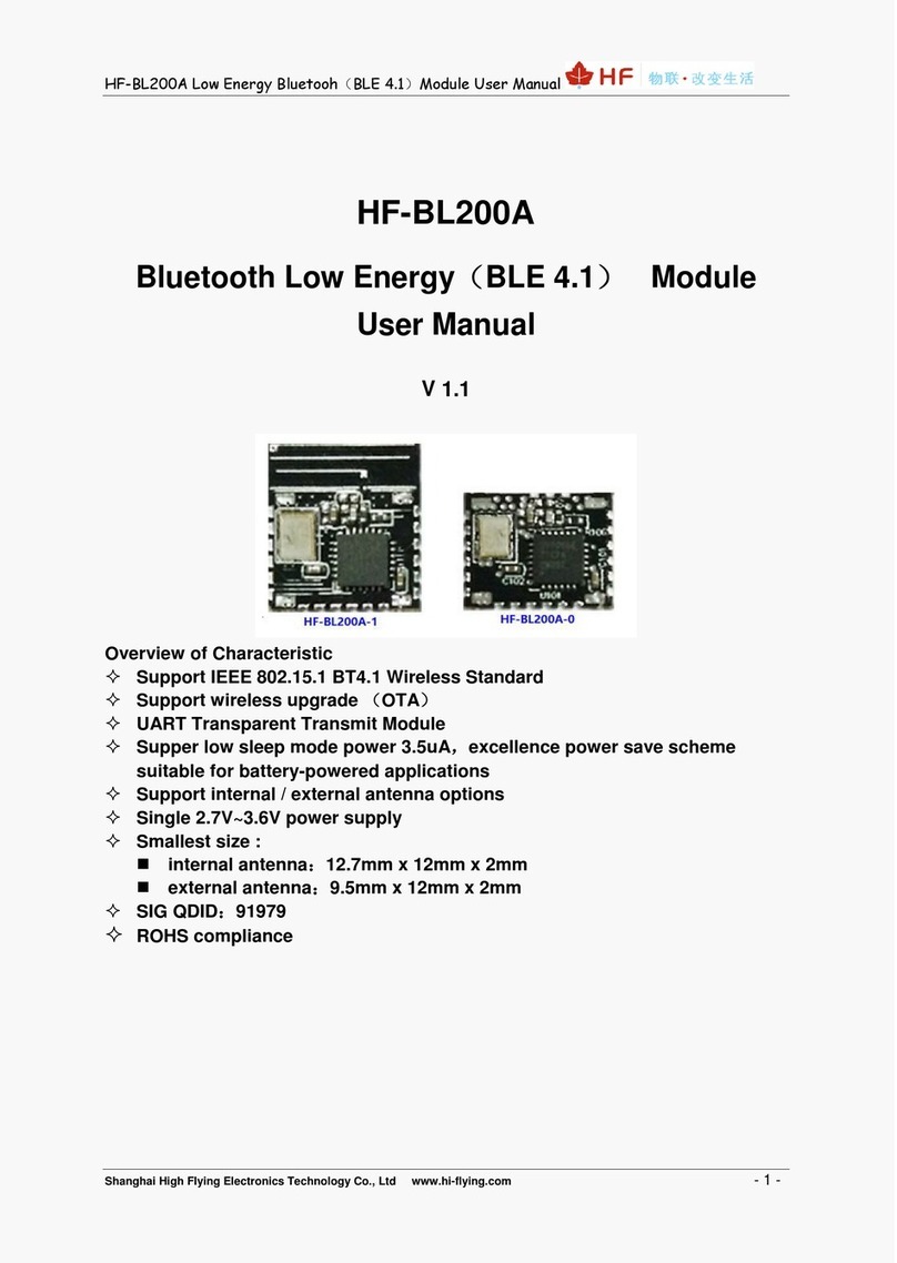
HF-BL200A
Bluetooth Low Energy(BLE 4.1)Module
User Manual
V 1.0
Overview of Characteristic
Support IEEE 802.15.1 BT4.1 Wireless Standard
Support wireless upgrade (OTA)
UART Transparent Transmit Module
Supper low sleep mode power 3.5uA,excellence power save scheme
suitable for battery-powered applications
Support internal / external antenna options
Single 2.7V~3.6V power supply
Smallest size :
internal antenna:12.7mm x 12mm x 2mm
external antenna:9.5mm x 12mm x 2mm
SIG QDID:91979
ROHS compliance

HF-BL100-CU Low Energy Bluetooh(BLE 4.1)Module User Manual
Shanghai High Flying Electronics Technology Co., Ltd www.hi-flying.com - 2 -
Table of Contents
LIST OF FIGURES...................................................................................................................................5
LIST OF TABLES ....................................................................................................................................5
1. PRODUCT OVERVIEW ...................................................................................................................7
1.1. General Description.................................................................................................................7
1.2. Device Feature..........................................................................................................................7
1.3. Key Application........................................................................................................................7
1.4. Device Parameter.....................................................................................................................8
1.5. Order information.....................................................................................................................8
2. HARDWARE INTRODUCTION .....................................................................................................10
2.1. Pin Definition..........................................................................................................................10
2.2. Electrical Specification..........................................................................................................12
2.3. Mechanical size......................................................................................................................13
2.4. Antenna Layout......................................................................................................................14
3. UART TRANSPARENT TRANSMIT MODE..................................................................................16
3.1. Transparent Transmit Mode..................................................................................................16
3.2. Transparent Transmit Mode Pin Description......................................................................18
3.3. Factory Default Parameter ....................................................................................................19
3.3.1. Device Name........................................................................................................................19
3.3.2. Broadcast Parameter ...........................................................................................................19
3.3.3. Transmit Power ....................................................................................................................19
3.3.4. Connect Parameter ..............................................................................................................19
3.3.5. Baud rate..............................................................................................................................19
3.3.6. Send Latency Parameter......................................................................................................19
4. UART AT COMMAND DEFINITION..............................................................................................20
4.1. Module Operation Mode Configure......................................................................................20
4.2. AT:Command Overview......................................................................................................20
4.2.1. Command Format.............................................................................................................21
4.2.2. Command List...................................................................................................................22
4.3. AT Command..........................................................................................................................24
4.3.1. Help command..................................................................................................................24
4.3.2. Set Module NAME ............................................................................................................24
4.3.3. Query module Name.........................................................................................................25
4.3.4. Set Connect Parameter ....................................................................................................25
4.3.5. Query Connect Parameter................................................................................................26
4.3.6. Set Baud rate....................................................................................................................27
4.3.7. Query Baud rate................................................................................................................27
4.3.8. Get MAC Address.............................................................................................................28
4.3.9. Query Software Version....................................................................................................28
4.3.10. Set Transmit Power.......................................................................................................28

HF-BL100-CU Low Energy Bluetooh(BLE 4.1)Module User Manual
Shanghai High Flying Electronics Technology Co., Ltd www.hi-flying.com - 3 -
4.3.11. Query Transmit Power ..................................................................................................29
4.3.12. Set Broadcast Parameter..............................................................................................30
4.3.13. Query Broadcast Parameter .........................................................................................30
4.3.14. Set User-define Broadcast Data ...................................................................................31
4.3.15. Query User-define Broadcast Data...............................................................................31
4.3.16. Set Auto-broadcast Switch............................................................................................32
4.3.17. Query Auto-broadcast Switch .......................................................................................32
4.3.18. Start Broadcast..............................................................................................................33
4.3.19. Stop Broadcast..............................................................................................................33
4.3.20. Query Current BLE Subsystem Status .........................................................................34
4.3.21. Disconnect.....................................................................................................................34
4.3.22. Set Device Verify Code.................................................................................................35
4.3.23. Query Device Verify Code.............................................................................................35
4.3.24. Set UART Output Data Latency....................................................................................36
4.3.25. Save Parameter ............................................................................................................37
4.3.26. Module Restore.............................................................................................................37
4.3.27. Set Module Operate Mode............................................................................................38
4.3.28. Module BLE subsystem Status Notification ..................................................................38
4.3.29. Module CPU Status Notification....................................................................................39
4.3.30. Restore Factory Setting via At Command.....................................................................39
4.3.31. Enable Module Deep Sleep ..........................................................................................39
4.3.32. Restore Factory Setting via Hardware Method.............................................................40
5. APP COMMAND............................................................................................................................41
5.1. Channel and Data Description..............................................................................................41
5.2. Data Format ............................................................................................................................41
5.3. Command Content.................................................................................................................42
5.3.1. Command Type:0x0E ....................................................................................................42
5.3.2. Command Type:0x0F.....................................................................................................42
6. BASIC COMMUNICATION MECHANISIM ...................................................................................44
6.1. Application Service Data Channel(user-define application service UUID:0x2B00).44
6.1.1. Module->APP, UART Data Channel【feature UUID:0x2B10】.......................................44
6.1.2. APP->Module,UART Data Channel【feature UUID:0x2B11】.....................................44
6.1.3. APP->Module,OTA Mode Switch【Feature UUID:0x2B12】........................................45
6.1.4. APP->Module,APP Command Channel【Feature UUID:0x2B13】..............................45
6.2. Battery Service Data Channel...............................................................................................45
6.2.1. APP->Module,Battery Data Channel 【Feature UUID:0x2A19】.................................46
6.3. OTA Service Data Channel....................................................................................................46
6.3.1. APP->Module,OTA Data Channel .................................................................................46
7. PACKAGE INFORMATION...........................................................................................................47
7.1. Reflow Soldering Profile .......................................................................................................47
7.2. Handling Instruction ..............................................................................................................47
7.3. Shipping Information.............................................................................................................48
APPENDIX A: UART TRANSPARENT TRANSMIT TYPICAL APPLICATION..........................49

HF-BL100-CU Low Energy Bluetooh(BLE 4.1)Module User Manual
Shanghai High Flying Electronics Technology Co., Ltd www.hi-flying.com - 5 -
LIST OF FIGURES
Figure 1. HF-BL200A order information ................................................................................................9
Figure 2. HF-BL200A Pin Definition ...................................................................................................10
Figure 3. HF-BL200A-0 Mechanical size.............................................................................................13
Figure 4. HF-BL200A-1 Mechanical size.............................................................................................14
Figure 5. HF-BL200A Module Reference Placement.........................................................................15
Figure 6. Basic HF-BL200A wireless network structure......................................................................16
Figure 7. HF-BL200A Default UART Parameter .................................................................................20
Figure 8. ”AT:HELP” list All command.................................................................................................21
Figure 9. Module UART Output Data Latency Set Map......................................................................37
Figure 10. Module UART Receive Enable Signal Map......................................................................40
Figure 11. Reflow Soldering Profile ...................................................................................................47
Figure 12. Package Information.........................................................................................................48
Figure 13. UART Transparent Transmit Typical Application .............................................................49
LIST OF TABLES
Table 1 HF-BL200A Module Technique Specification ............................................................................8
Table 2 HF-BL200A Pin Function Definition..........................................................................................10
Table 3 Limited Specification ................................................................................................................12
Table 4 Electrical Specification .............................................................................................................12
Table 5 RF specification........................................................................................................................12
Table 8 Module connect interval 20ms communication mode example ..............................................17
Table 9 Error Code list...........................................................................................................................22
Table 10 AT Command List...................................................................................................................22
Table 11 Command Data from APP to Module.....................................................................................41
Table 12 Feedback Data from Module to APP......................................................................................41
Table 13 Command Type 0x0F command list........................................................................................42
Table 14 Command Type 0x0F Feedback List ......................................................................................43
Table 15 Description of User-define Service of All Channnel............................................................44
Table 16 0x2B10 feature UART Module->APP Channel Description................................................44
Table 17 0x2B11 Feature UART APP->Module Channel Description...............................................44
Table 18 0x2B12 Feature OTA Mode Switch Channel Description...................................................45
Table 19 0x2B13 Feature APP Command Channel Description .......................................................45
Table 20 Description of Battery Service of All Channel .........................................................................45
Table 21 0x2A19 Feature Battery Power Channel Feature Description............................................46
Table 22 Description of OTA Service of All Channel ..........................................................................46
Table 23 Feature OTA Data Channel Feature Description.................................................................46
Table 24 Reflow Soldering Specification...............................................................................................47

HF-BL100-CU Low Energy Bluetooh(BLE 4.1)Module User Manual
Shanghai High Flying Electronics Technology Co., Ltd www.hi-flying.com - 7 -
1.PRODUCT OVERVIEW
1.1. General Description
HF-BL200A Bluetooth Low Energy module is a high performance IOT module designed by High Flying.
It is based on Cypress chip, and provide a solution for connecting things to Bluetooth wireless
network and data transmitting via UART interface. With the feature of low power, small size, high anti-
interference performance, the module integrates PCB antenna and use open stamp type interface
which enable customer have more flexibility on software and product structure , and solve the RF
hardware design and debug issue.
1.2. Device Feature
2.7~3.6V Single power supply Smallest size
internal antenna:12.7mm x 12mm x 2mm
external antenna:9.5mm x 12mm x 2mm
With 32 bit high performance RISC 48MHz ARM M0 MCU,MCU build-in 12KB SRAM and
512KB Flash
Support low power & multiple level power management mode
Full peripheral interface
GPIO interface
Serial Communication(UART application)
ADC interface
FCC/CE/BQB
ROHS compliance
1.3. Key Application
Smart LED lighting
Smart toy
Electronic Scale
Smart Cup
Smart Home Appliance
OBD
IOT, Smart Home Automation
Sports, fitness, customer electronics products
Smart instrument, data acquisition ,sensor
PC, Tablet peripheral interface

HF-BL100-CU Low Energy Bluetooh(BLE 4.1)Module User Manual
Shanghai High Flying Electronics Technology Co., Ltd www.hi-flying.com - 8 -
1.4. Device Parameter
Table 1 HF-BL200A Module Technique Specification
Power details refer to Table 6
1.5. Order information
As customer demand, HF-BL100-C can provide variant physical version, detail part number as
below:
Class
Item
Condition
Parameter
Wireless
paramete
r
Certificate
BQB
Wireless
standard
802.15.1
Frequency
range
2.402GHz-2.480GHz
Data rate
Tx power
Max=+10 dBm,
Rx sensitivity
-93 dBm
Hardware
paramete
r
Data
interface
UART
SPI,I2C
PWM
Operating
voltage
2.7~3.6V
Power
consumption
Dormant
2uA
Sleep
3~11uA
DIG Active
5mA
RF Active
20mA
Average
power
consumption
20ms broadcast
3.2mA
0.5ms broadcast
130uA
4s broadcast
1.3uA
30ms connection
19uA
100ms connection
290uA
4s connection
10uA
Work
temperature
-40℃- 85℃
Storage
temperature
-45℃- 125℃
Size
HF-BL200A-1:12.7mm x 12mm x 2mm
HF-BL200A-0:9.5mm x 12mm x 2mm

HF-BL100-CU Low Energy Bluetooh(BLE 4.1)Module User Manual
Shanghai High Flying Electronics Technology Co., Ltd www.hi-flying.com - 9 -
HF-BL200A-X Model
1-> Built-in PCB antenna
0-> External pad antenna
Module Version
BL100->Bluetooth BLE Single mode
Company name
HF->Hi-Flying
Figure 1. HF-BL200A order information

HF-BL100-CU Low Energy Bluetooh(BLE 4.1)Module User Manual
Shanghai High Flying Electronics Technology Co., Ltd www.hi-flying.com - 10
-
2.HARDWARE INTRODUCTION
2.1. Pin Definition
Figure 2. HF-BL200A Pin Definition
Table 2 HF-BL200A Pin Function Definition
Pin
Net name
Features
Description
1,2,13
19,21
GND
Power
Ground
3
VEQ
Power
e-fuse parameter programming pin, please leave it
blank.
4
IO23
D/A I/O
GPIO/AIO 1
5
IO24
D/A I/O
Add 4.7K resister external
GPIO/PWM0/AIO2
6
IO01
D/A I/O
GPIO/SPI-M CLK/PWM1/AIO3
7
IO02
D/A I/O
GPIO/SPI-M MISO/PWM2/AIO4
8
MANUFACTURE
DIG I/O
Add 4.7K resister external

HF-BL100-CU Low Energy Bluetooh(BLE 4.1)Module User Manual
Shanghai High Flying Electronics Technology Co., Ltd www.hi-flying.com - 11
-
Pull high for more than 5 seconds to restore the factory
settings, IO03/SPI-M CSN/PWM3
9
WAKE
DIG I/O
Pull low to wake up Bluetooth
IO04 / SPI-M MOSI / PWM4
10
BCTS
DIG I/O
The default output low, high data output is sent, used to
wake up the MCU, the data is sent after the output low
IO05 / I2C-M
11
IO06
DIG I/O
GPIO/I2C-M
12
VDD
Power
Power input, 2.7V ~ 3.6V
14
UART_TX
DIG I/O
3.3V TTL
IO09
15
UART_RX
DIG I/O
3.3V TTL
IO10
16
RESET
DIG I
Hardware reset, active low
17
UART_DEB_TX
DIG I/O
Debug UART_TX
IO15
18
UART_DEB_RX
DIG I/O
Debug UART_TX
IO16
20
RF
RF
RF antenna pin
note:
1, In normal startup, IO03 and IO24 must be connected with 4.7K pull-down resistor. When it
needs to enter programming mode, reset IO03 and use UART_DEB_TX and UART_DEB_RX to
program the program.

HF-BL100-CU Low Energy Bluetooh(BLE 4.1)Module User Manual
Shanghai High Flying Electronics Technology Co., Ltd www.hi-flying.com - 12
-
2.2. Electrical Specification
Table 3 Limited Specification
Parameter
Description
Min
Value
Typ.
Value
Max
value
Unit
VPIN
Pin voltage limit
-0.1
-
VDD
V
T_VRISE
Power up time
5
-
100
mS
ESD_HBM
4000
V
ESD_MM
100
V
ESD_CDM
500
V
Storage temperature
range
-50
150
°C
Table 4 Electrical Specification
Parameter
Condition
Min
Value
Typ.
Value
Max
Value
Unit
Work voltage
2.7
3.3
3.6
V
Work temperature
-40
85
°C
I_DORM
Dormant status
2
uA
I_SLEEP
Sleep status
3
uA
I_TX0DBM
TX Mode 0dBm
23
mA
I_TX10DBM
TX Mode, 10dBm
45
mA
I_TXN20DBM
TX Mode -20dBm
15
mA
I_RX
RX default
20
mA
System clock =24Mhz
7.1
mA
System clock =12Mhz
4
mA
System clock =6Mhz
2.5
mA
System clock =3Mhz
1.7
mA
Sleep mode
Operating 3Mhz
1.1
mA
Deep sleep mode
ECO Stop,WCO work
1.3
uA
Stop mode
ECO Stop,WCO work
60
nA
Table 5 RF specification
Parameter
Condition
Min value
Typ. Value
Max value
Unit
Receiving
sensitivity
-93
dBm
Operating
frequency range
2400
2483
MHz
Frequency
deviation
225
250
275
KHz
Output Power
19
dBm
Frequency
tolerance
±50
Ppm

HF-BL100-CU Low Energy Bluetooh(BLE 4.1)Module User Manual
Shanghai High Flying Electronics Technology Co., Ltd www.hi-flying.com - 13
-
Signal strength
accuracy
±5
dBm
Signal accuracy
1
dBm
2.3. Mechanical size
HF-BL200A physical size (unit: mm)as below:
HF-BL200A-0 Pads: Size 9.5mm X 12mm, pad pitch 1.27mm
Figure 3. HF-BL200A-0 Mechanical size
HF-BL200A-1 Pads: Size 12.7mm X 12mm, pad pitch 1.27mm

HF-BL100-CU Low Energy Bluetooh(BLE 4.1)Module User Manual
Shanghai High Flying Electronics Technology Co., Ltd www.hi-flying.com - 14
-
Figure 4. HF-BL200A-1 Mechanical size
2.4. Antenna Layout
HF-BL200A supports internal antenna.. Customers need to obey following antenna design rules
and module location suggestions:
For user PCB, place module on the edge area of the PCB as possible, or suspend the
antenna area.
Module antenna(5mmx12mm)correspondent area can’t put components or paste GND,
the surrounding components or GND should be as far as possible from antenna place.
Antenna must be away from high components at least 10mm.
Antenna can’t be shielded by any metal enclosure.
High Flying suggests to locate HF-BL200A as Figure 5 to reduce the influence to antenna and
wireless signal as much as possible, or contact High Flying technique people for support

HF-BL100-CU Low Energy Bluetooh(BLE 4.1)Module User Manual
Shanghai High Flying Electronics Technology Co., Ltd www.hi-flying.com - 16
-
3.UART TRANSPARENT TRANSMIT MODE
3.1. Transparent Transmit Mode
Transparent Transmit means the two way communication between device and mobile terminal via
the connecting with serial interface and device MCU. Device can set HF-BL200A baud rate and
connect interval via AT command through serial interface (refer to “Serial AT command
Description”for details). Target different baud rate and BLE connect interval or different packet
sending interval, module would have different data handling capacity. The default baud rate of HF-
BL200A is 115200bps, it is recommended to set baud rate at 115200bps when transmitting big
data or in highly real-time application. Baud rate support save after power off.
Figure 6. Basic HF-BL200A wireless network structure
Module BLE connect interval is 20ms, and it is able to send almost 200 byte data one time via
serial interface. Theoretically, module is able to send data up to 4KB/S. Below is the detail description
about transparent transmit.
Module can receive almost 200 byte data from serial interface one time. Module will automatically
send sub-packet according to data size, each packet limit is 20 bytes. The data packet sending from
mobile device to module must be separated to sub-packet(1-20 byte each). After receiving the sub-
packets, module will send to MCU in proper order.
Serial hardware protocol: 115200 bps, 8,non-parity, 1 stop bit
After receiving data from MCU serial port, module will judge if it is AT command. If it is, module
will execute the command. If not, module will transmit the data to APP under BLE connection and
notify mode enabled status.
After module receives APP data, it will output the data to MCU via serial interface.

HF-BL100-CU Low Energy Bluetooh(BLE 4.1)Module User Manual
Shanghai High Flying Electronics Technology Co., Ltd www.hi-flying.com - 17
-
If module system status changed, module will send status notification character to MCU, such as
disconnect, connect, broadcast.
Bluetooth protocol require that the minimum connect interval is 7.5ms. Default connect interval is
20ms (comply with IOS regulation), if it is needed to save power and apply low speed transmit mode.
User can adjust connect interval through AT command ( the maximum connect interval is 2000ms,
comply with IOS regulation)
The calculation of transmit speed : the data packet of each connection interval from APP to
module is 1 packet, max 4 packet can be transmitted from module to APP in each interval (the packet
is related to module CPU capacity) . There is maximum 20 bytes in each packet, if connect interval is
T (unit :ms), then max transmit speed V (unit is byte/s) is :
Vmodule = 20*4*1000/T (V only related T )
Vapp=20*1000/T (V only related T )
Vapp:if module connect interval is 20ms, then each interval can transmit max 20 bytes, so
theoretically the max speed is 20x50 =1k byte/s. Test shows the transmit from APP to module is
stable and reliable.
Vmodule:if module connect interval is 20ms, then each interval can transmit maximum 80 bytes,
so theoretically the maximum speed is 80x 50=4k byte/s. Test shows that if transmit speed is under
2kbyte/s, there is few chances of leaking packet. For safety consideration, it is recommended to do
verification and re-transmit at up level whatever it is low speed or high speed application. In Android
application, it is recommended to lower connect interval to increase speed.
Below is the example of 20ms connect interval communication mode, user can self-configure. The
lower the Speed, the lower the packet lost ratio.
Table 8 Module connect interval 20ms communication mode example

HF-BL100-CU Low Energy Bluetooh(BLE 4.1)Module User Manual
Shanghai High Flying Electronics Technology Co., Ltd www.hi-flying.com - 18
-
Remark:user can set particular communication mode according to actual application, packet
length can be set between 80byte < L < 200byte ,the relationship as below as per BLE protocol:
If L<80 ,TS >= T ;
If 80<L<160 ,TS >= T*2 ;
If 160<L<200 ,TS >= T*3 ;
All transmit mode is safe as long as it meets above conditions, TS=T is recommended,
TS=T*2,TS=T*3 is ok but the packet lost ratio is high, must add verification and re-transmit
mechanism. In another words, if apply 80byte < L < 200byte ,serial data can transmit to module in one
time, but need to reserve time for sending data from module to Bluetooth, or there will occur rear-end.
E.g. Set connect interval T=20ms, if data length is L=200, TS must over T*3 = 60ms , TS=70ms is a
reasonable choice.
Serial data length can be any value under 200 byte. In order to achieve the best efficiency and
avoid full load operation , it is recommended to use 20,40,60 byte serial data packet, set packet
interval over 20ms.
Remark:in IOS, the function is used to call Characteristic is:
BCharacteristicWriteWithRespons
e parameter, “write with response”mode would lower transmit efficiency to ensure the accuracy
of each packet. Using “CBCharacteristicWriteWithoutResponse” ; “write without response”mode
would promote transmit efficiency , but the accuracy of packet need to be verified by APP up level.
3.2. Transparent Transmit Mode Pin Description
All pins of Transparent Transmit :UART_TX、UART_RX、WAKEUP、BCTS、XRES、
MANUFACTURE
Min. pins of Transparent Transmit:UART_TX、UART_RX、WAKEUP
Details refer to 《Appendix A》
WEAKEUP: inside high impedance, pin must be connected. Pull up to stop UART receive
function. UART is unable to receive data (UART able to send data). Pull down to enable UART to
receive data.
MANUFACTURE: Pull down inside, and it can be no connection. Pull up outside and power on or
reset, keep high level MANUFACTURE at least 5 second. Module restore factory setting
XRES: Pull up inside, can be no connection
BCTS: In normal time, output low level; BCTS output high level before sending data from module,
after sending , BCTS output low level.

HF-BL100-CU Low Energy Bluetooh(BLE 4.1)Module User Manual
Shanghai High Flying Electronics Technology Co., Ltd www.hi-flying.com - 19
-
3.3. Factory Default Parameter
3.3.1. Device Name
Device NAME:”HF-BL200A”
3.3.2. Broadcast Parameter
Broadcast Min. interval:“0800”, means 500ms
Broadcast Max. interval::“0800”, means 500ms
Broadcast type:“0”,means public
Broadcast channel :“7”,means apply channel index 37 38 39
3.3.3. Transmit Power
Broadcast transmit power :”8”,means 0dbm
Connect transmit power:”8” means 0dbm
3.3.4. Connect Parameter
Min interval :”0016”, means 20ms
Max interval:”0032”, means 40ms
Slave Latency:”0”, means 0
Connect timeout:”0200”, means 2000ms
3.3.5. Baud rate
Baud rate:“115200”
3.3.6. Send Latency Parameter
Serial sending Latency :“01”,means 1ms

HF-BL100-CU Low Energy Bluetooh(BLE 4.1)Module User Manual
Shanghai High Flying Electronics Technology Co., Ltd www.hi-flying.com - 20
-
4.UART AT COMMAND DEFINITION
4.1. Module Operation Mode Configure
After HF-BL200A power on, module enter transparent transmit mode, default UART
configuration parameter is as below:
Figure 7. HF-BL200A Default UART Parameter
User can configure the module via AT command through UART or use Evaluation Kit to test.
Evaluation kit refer to Appendix B.
<Description>:AT command debug tool recommend use “ friend serial debug assistant”and
SecureCRT tool ,which can be download from company website.
4.2. AT:Command Overview
AT: command can be inputted via serial debug tool or compile as below photo shows, AT:HELP is
a help command, list all commands and description.
Remark: the end of each command need add return or line feed character.
This manual suits for next models
3
Table of contents
Other HF Control Unit manuals
Popular Control Unit manuals by other brands
Vaillant
Vaillant Control Center VR 65 installation instructions
Asco
Asco 8320 Series Installation & maintenance instructions
Faderfox
Faderfox NEW MODULE PC12 user manual
Sanhua
Sanhua RFKH Series instructions

Bike Sport Developments
Bike Sport Developments Blip Box-Pro manual
weinor
weinor BiEasy 1M operating manual


