HGLRC Sector 5 V3 VTX User manual

2
www.hglrc.com
Product Specifications.............................................................................................................................1
Interface Description...............................................................................................................................2
Check the flight control drive................................................................................................................3
Calibration accelerometer......................................................................................................................4
UART serial port use.................................................................................................................................5
Select aircraft model.................................................................................................................................6
Choose ESC protocol..................................................................................................................................7
Select ESC telemetry..................................................................................................................................8
Voltage and current parameters setting.............................................................................................9
Setting up the receiver..............................................................................................................................10
VTX serial port use.DJI serial port use...............................................................................................11
GPS parameters setting...........................................................................................................................12
Check receiver signal................................................................................................................................13
Select flight mode startup mode...........................................................................................................14
OSD settings.................................................................................................................................................15
LED settings.................................................................................................................................................16
Troubleshooting.........................................................................................................................................17
.......................................................................................
Package IncIuded
Sector 5 V3 FPV Racing Drone*1
Accessory Package*1

3
www.hglrc.com
1.Product Specifications
Product parameters
Model
Sector 5 V3 FPV Racing Drone
Frame Kit
Sector 5 V3 Frame Kit
Flight Controller
Zeus F722 Flight Controller
ESC
48A 4in1 ESC
VTX
Zeus VTX 800MW
Camera
Caddx Ratel 2 Camera
Motor
AEOLUS 2306.5 Motor
4S KV2550
6S KV1900
Support Neceiver
SBUS .PPM .DSMX
Input Voltage
3-6S Lipo
Weight
444.3g

4
www.hglrc.com
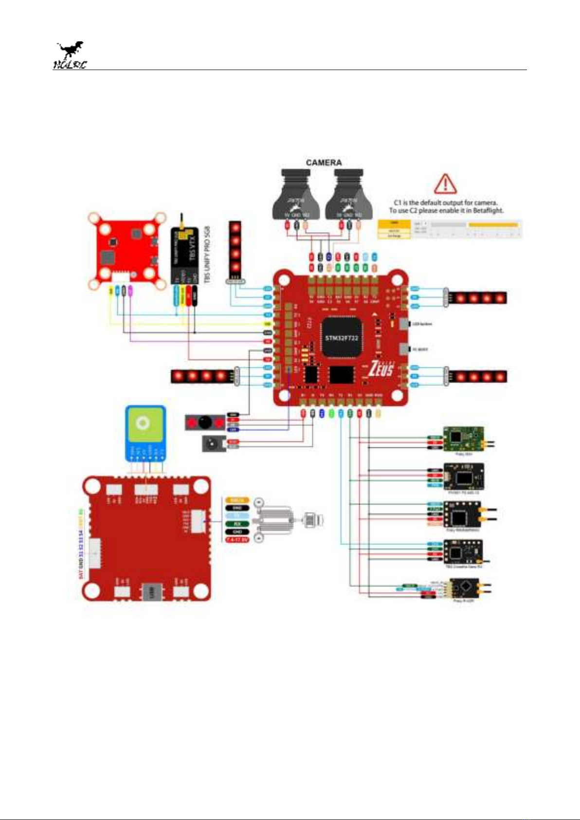
2.Interface Description

5
www.hglrc.com
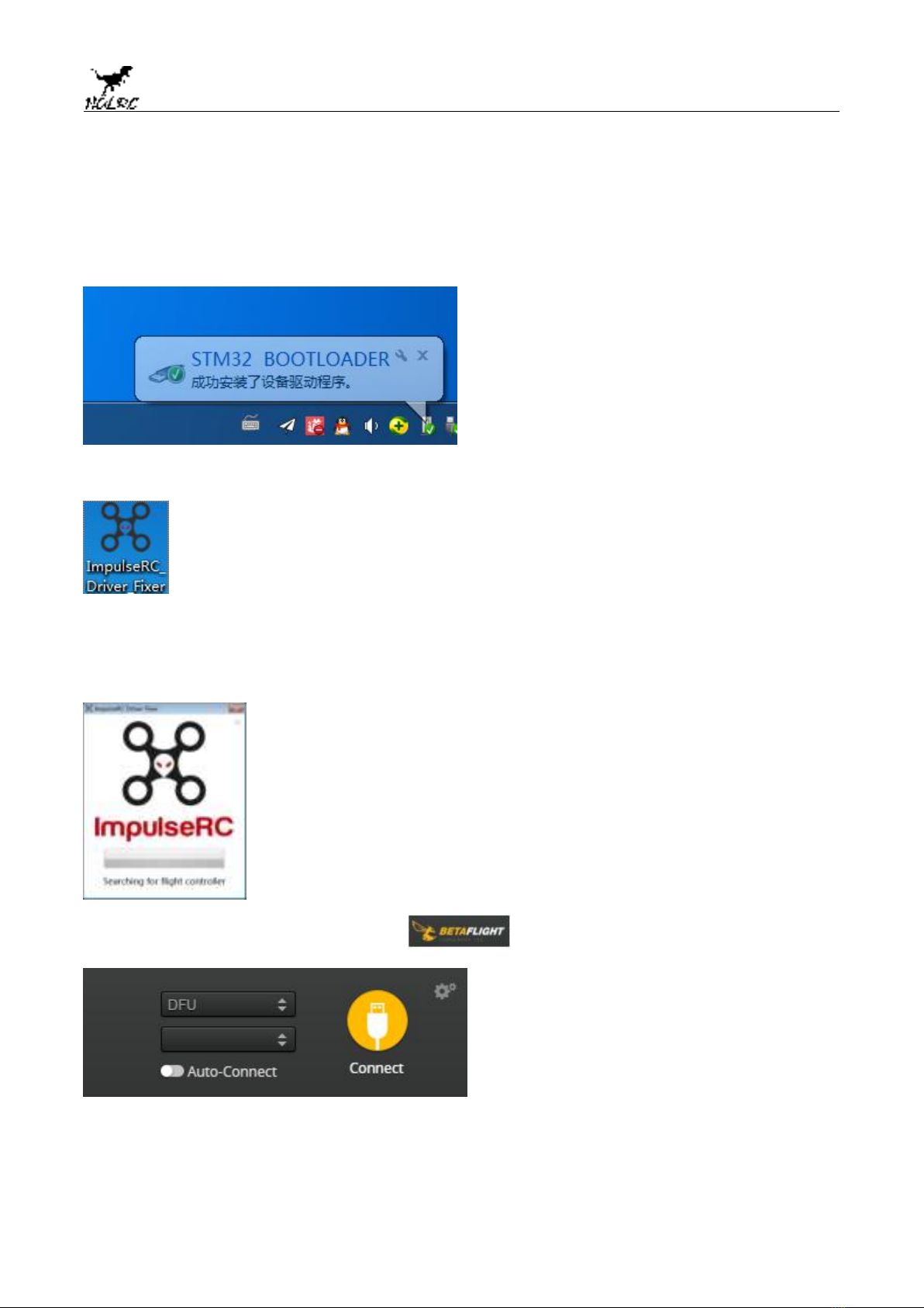
3.Check the flight control drive
1. Long Press BOOT buttons.connect USB.The system automatically
install the driver
2.Driver cannot be installed, please download ImpulseRC_Driver_Fixer
3.Double-click on the run(Plug in the flight controller to automatically
install the driver)
4.open betaflight configurator ,enter DFU mode

6
www.hglrc.com
5.Click Select firmware version
6.Click Load firmware.Waiting for
completion It will be prompted upon
completion.
7. open betaflight configurator .Controller plugged into the
computer. Betaflight Automatically assigned port,
click “Connect” Enter
setup interface(Different computer COM)

7
www.hglrc.com
4. Calibration accelerometer
1. Put the aircraft horizontal and click“Reset Z axis”
Click again
5.UART serial port use
1.UART1 uses the receiver
2.UART2 uses GPS
3.UART3 uses 5.8G VTX
4.UART4 uses DJI
5.UART6 uses ESC telemetry

8
www.hglrc.com
6.Select aircraft model
1.Click Select model
2.Click Click “I understand the risks”
Push Master to check motor
steering“Master”Steering can be changed at BLHeliSuite

9
www.hglrc.com
7.Choose ESC protocol
1.Choose the right ESC protocol, the optional universal protocol
DSHOT600.
8.Turn on ESC telemetry
1.Use BLHeli_32 ESC telemetry over a separate wire
2.Open ESC telemetry serial port.TX on the ESC needs to be connected
to the RX6 on the flight controller to use the ESC telemetry

10
www.hglrc.com
3.View telemetry data on OSD
9.Voltage and current
parameters setting
1.Click Setting parameters

11
www.hglrc.com
10.Setting up the receiver
1.Receiver connection diagram
2.Click .have found“UART1”Open the receiver serial port

12
www.hglrc.com
3.Set the SBUS receiver
4.Set the PPM receiver
5.Set the DSMX receiver
6.Set the CRSF receiver

13
www.hglrc.com
11.VTX serial port use wiring .
1. 5.8VTX connection
2. DJI FPV Air Unit wiring

14
www.hglrc.com
3. 5.8G VTX serial port opens. The protocol is selected according to its
own VTX protocol.
4. DJI serial port opens
5.Use OSD to adjust VTX
which displays information like battery voltage and mAh consumed while you fly. In addition, the
Betaflight OSD can be used to configure the quadcopter, making in-field adjustments and tuning more
convenient.
MODE2 MODE1

15
www.hglrc.com
The graphics above show the stick command to bring up the OSD menu. The stick command is: throttle
centered, yaw left, pitch forward. The exact stick command therefore depends on which mode your
transmitter sticks are in.
In the OSD menu, use pitch up/down to move the cursor
between menu items. When a menu option has a > symbol
to the right of it, this indicates that it contains a sub-menu.
Roll-right will enter the sub-menu. For example, in the
screen to the right, moving the cursor to “Features” and
then moving the roll stick to the right will enter the
“Features” sub-menu.
If you are using a video transmitter that supports remote
configuration, enter the “Features” menu to configure the
vTX. From there, enter either “VTX SA” if you are using
SmartAudio (TBS Unify) or “VTX TR” if you are using IRC
Tramp Telemetry.
To adjust PIDs, rates, and other tuning-related parameters,
enter the “Profile” sub-menu.
In the “Scr Layout” sub-menu, you can move the OSD
elements (like battery voltage, mAh, and so forth) around on
the screen.
The “Alarms” sub-menu lets you control when the OSD will
try to alert you that battery voltage is too low or mAh
consumed is too high.
When a parameter can be modified, the parameter’s current
value will be shown on the right-hand side of the screen. In
this case, roll left/right will adjust the parameter up and
down.
The screen to the right shows the current vTX settings. Fromhere, you can change the frequency band,
channel, and
power level of the video transmitter. After making the
changes, move the cursor to “Set” and press roll-right to
confirm the settings.

16
www.hglrc.com
12.GPS parameters setting
1. GPS connection
2.Open the GPS serial port

17
www.hglrc.com
3.When using the GPS function, remember to configure the serial port
(via the Ports tab).
13.Check receiver signal
1.Click Check Check the remote control output signal

18
www.hglrc.com
14.Select flight mode startup
mode
Click set up the function of remote control switch across the
channel (below are for reference only)
15.OSD settings
1. Click the OSD Settings, according to the need to choose, drag
the OSD schematic diagram of the parameters can be adjusted.

19
www.hglrc.com
16.LED settings
1.LED function buttons:
Short press to switch colors.
Press and hold for 3 seconds to enter the blinking mode switch
(LED status light is always on)
2.Blinking mode:
Steady / Fast Flash / Breathing Light / Colorful Slow Flash
3.LED light can be controlled via CH5(AUX1) of transmitter with
Channel_Forwarding enabled.
Click enter:
resource servo 1 A08
SAVE
4. Click Forward aux channels to servo outputs
5.Click Turn on LED support

20
www.hglrc.com
6.Click .Click set according to
need
17.Troubleshooting
Warning:
Please read the cautions as follows, otherwise stability of your flight
controller cannot be ensured, your flight controller will even get damaged.
●Keep focus on the polarity. Check carefully before power supply.
●Cut off the power when you connect, plug and pull anything.
●The refresh rate of PID and Gyroscope is up to 8K/8K.
Table of contents
Other HGLRC Drone manuals

HGLRC
HGLRC Veyron3 HD User manual

HGLRC
HGLRC Rekon6 LR User manual

HGLRC
HGLRC Racewhoop30 User manual

HGLRC
HGLRC Wind6 User manual

HGLRC
HGLRC Sector 5 V2 User manual

HGLRC
HGLRC Racewhoop30 User manual

HGLRC
HGLRC Arrow3 6S User manual

HGLRC
HGLRC Racewhoop25 HD User manual

HGLRC
HGLRC Petrel 75Whoop User manual

HGLRC
HGLRC Sector4 FR Freestyle FPV Drone HD User manual