Step 1 - Separate the runner components (see Fig 2a & 2b)
• Place the mounting panel upside down on a at surface with the runners facing upwards.
• Fully extend the runners.
• Find the black levers located on the outer side of both the left and right runner.
• Simultaneously, push the left lever down and the right lever up and pull inner of the runners towards you until it separates completely
from the unit. Set runner inner with collar, handle/door bracket attached aside in a safe location.
• Push the outer runners attached to the mounting panel back inside the unit.
Step 2 - Remove the friction-tted lid from mounting panel (see Fig 3a, 3b & 3c)
• Mounting panel should still be upside down on a at surface with the runners facing upwards.
• To remove the friction-tted lid - push rmly down on the lid at the back of the unit.
• Push rmly, distributing pressure to both sides of lid to ensure the lid clears the hooks located on the left and right hand sides of
the mounting panel (g 3b).
• Simultaneously, pull the friction-tted lid forwards until it clears the mounting panel (g 3c).
• Pull the foam pad clear of the mounting panel. Set aside, leaving the plastic cover on.
Step 3 – Predrill the Carcase
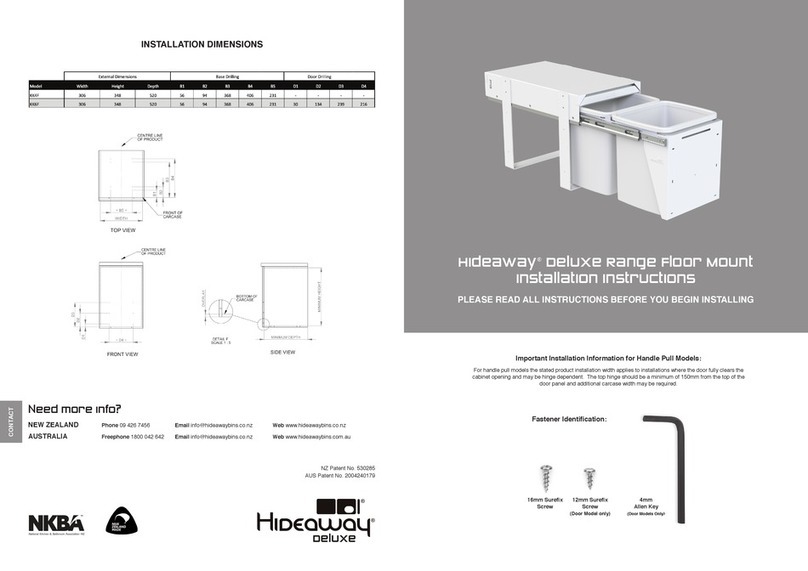
• Refer to the Installation Dimensions on the back page of these instructions.
• Mark out the mounting positions to be used and drill a 2mm hole 10mm deep at each point.
Step 4 – Installing the Mounting Panel in the Carcase
• Position the mounting panel within the carcase.
• Use the 16mm Surex screws and the washers in top mount locations.
• Use the 16mm Surex screws in side mount locations. Note: A #1 Square Drive or #2 Phillips Drive bit may be used.
Step 5 - Reinstall the friction-tted lid and foam into mounting panel
• Rest the foam on top of the friction-tted lid - the at side of the friction-tted lid should be towards the ground with the folds facing upwards.
• Slide the friction-tted lid and foam inside the mounting panel, stopping just before the rear hooks. (Note: the large fold on the friction-tted lid sits at
the front of the unit, and the rear of the lid has the slots which reconnect with the hooks located on the mounting panel at the rear).
• Simultaneously, with one hand, push rmly up on the back of the friction-tted lid, push the lid above the hooks and drop into location. Whilst this is
happening, with the other hand push the front of the lid upwards to ensure it rests on the metal support - located at the front of the mounting panel
(g 3c).
• The lid should move up and down slightly, with ease indicating correct installation.
Step 6 – Predrilling the Door Panel (Door Pull Models Only)
• Mark a vertical centre line down the rear of the door panel.
• Mark the overlay at the top of the door panel.
• With reference to the Installation Dimensions mark the D2 Door Mount positions.
• Drill a 2mm hole 10mm deep at each of the marked positions.
Step 7 – Mounting and Adjusting the Door Panel (Door Pull Models Only)
• Position the door bracket on the door panel and align with the predrilled holes.
• Secure the door bracket using a 12mm Surex Screw in each of the 2 vertical slots.
• Reattach the runner inners – Refer to FIG 2.
1. Ensure the runner outers attached to the mounting panel are pushed as far as they will go into the unit.
2. Ensure the runner inners are as far forward as they will go.
3. Line up the runner inners (with the collar handle/door bracket attached) to the runner outers.
4. Push the runner inners into position until the unit is fully closed. There may be some resistance when pushing the unit closed but
the runner should operate smoothly after reassembly.
• Adjust the angle of the door panel by loosening the two M6 nuts and bolts, moving the door bracket so it is parallel with the carcase and
retightening the M6 nuts and bolts.
• Adjust the vertical position of the Door Panel by loosening the 2 Surex Screws in the vertical slots and moving the panel as required.
• Drill a 2mm pilot hole 10mm deep at the centre of each of the horizontal slots.
• Secure the door panel using 12mm sure x screws through the 4 horizontal slots.
• If required adjust the horizontal position of the door panel by removing the 2 screws in the vertical slots, loosening the screws in the horizontal
slots, adjusting the panel position and retightening the screws in the horizontal slots.
• Reinstall the 2 screws into the vertical slots. Additional pilot holes may need to be drilled.
Step 8 - Place bin bucket/s into checkouts on collar
• Fully extend the runners.
• Place bucket/s into the checkouts provided on the collar of the unit. If the bucket/s do not sit within these checkouts the unit will
not close properly.
• Please leave the Care and Maintenance Instructions inside the bucket for the owner.
INSTALLATION INSTRUCTIONS START HERE
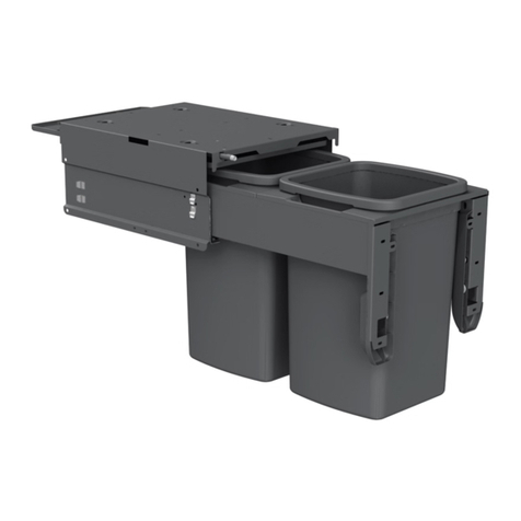
Top and/or side mounting points
Friction-tted lid
Liner holder
Runners
Mounting
panel
Bucket
Runners engaged - push left lever down
and right lever up
Runner Outer Runner Inner
Black lever on runners
Runner Outer Runner Inner
Pull the inner runner out until it separates
from the unit
Runners disengaged - pull the runner inner
clear of the outer
Lid coming free
of hook
Hook
Push rmly on the back of the unit to ensure the
lid clears the hooks located on the right and left
hand sides of top mounting panel
Metal support
The unit should look like this with the friction
tted lid and and foam pad removed
FIG 1 - Bin Parts FIG 2a - Removing Runners FIG 2b - Removing Runners FIG 3a FIG 3b FIG 3c


