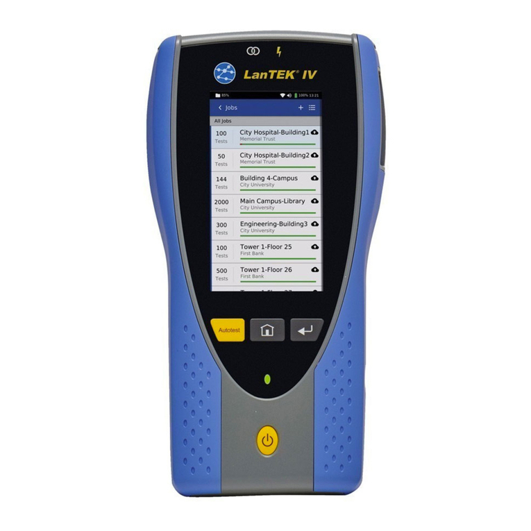
IDEAL Networks LanTEK IV Instruction Manual

1
Proof of Performance
PB www.idealnetworks.net
Proof of Performance
LanTEK IV
The Future of Cable
Certification
User Manual

2www.idealnetworks.net
LanTEK IV
User Manual
IDEAL INDUSTRIES Networks Ltd.
Stokenchurch House
Oxford road
Stokenchurch
High Wycombe
Buckinghamshire
HP14 3SX
United kingdom
© IDEAL INDUSTRIES Networks Ltd 2020
The information contained in this document is the property of IDEAL INDUSTRIES Networks Ltd. and
is supplied without liability for errors and omissions. No part of this document may be reproduced
or used except as authorized by contract or other written permission from IDEAL INDUSTRIES
Networks Ltd. The copyright and all restrictions on reproduction and use apply to all media in which
this information may be placed. IDEAL INDUSTRIES Networks Ltd. pursues a policy of continual
product improvement and reserves the right to alter without notice the specification, design, price or
conditions of supply of any product or service. All rights reserved.

3
Proof of Performance
2www.idealnetworks.net
Content
Safety Instructions 4
Responsibilities 5
Certification Link Models 6
IDEAL AnyWARE Cloud 8
LanTEK IV Configuration: Settings Menu 11
Default Autotest Settings 12
Wi-Fi Settings 13
Importing/Exporting Jobs 14
User Interface Operating Modes 15
Standard User Interface Operation - explained 16
Live Wiremap 23
Creating Test Files 24
Presentation of Tests 37
Performing Tests 39
Display of Test Results 41
Test List Options 47
Filtering Display of Test Results 49
Jobs Management and Synchronization 51
Folder Management and Synchronization 54
Technical Specifications of Cable Certifiers 56

4www.idealnetworks.net
Safety instructions
Warnings for handling the rechargeable batteries of LanTEK IV.
All Lithium-Ion (Li-Ion) batteries generate a significant flow of electric current,
irrespective of the indicated state of charge, which can cause personal injury and / or
property damage.
Lithium ion (Li-Ion) batteries should not be burned or disposed of with normal waste.
Lithium-ion (Li-Ion) batteries can explode if exposed to flame. Rechargeable batteries
are special waste and can contaminate groundwater if not disposed of properly.
Automatic resetting fuses in rechargeable batteries, which cut o high current
discharge as quickly as possible, ensure the greatest possible safety. However, these
fuses cannot provide full protection against transient arc discharges, which can occur
through a short circuit of the electrical contacts in the rechargeable battery. To avoid
injury, the following instructions for handling rechargeable batteries must be observed.
When a rechargeable battery is not installed in the tester handser, it must be stored in
clean, dry and non-conductive packaging.
Take care that the contacts of the rechargeable battery do not touch conductive
materials.
Avoid touching the contact surfaces of the rechargeable battery.
Rechargeable batteries can be recharged when they are the tester or by the external
charging port with the provided power supply. Charging the rechargeable battery in any
other way may cause it to explode.
Rechargeable batteries should only be placed, transported, stored and charged in a
non-explosive environment.
Observe service and storage temperatures.
Do not leave children or people who are not familiar with the safety instructions in this
user manual, handle or charge the rechargeable batteries.
Do not open the rechargeable battery case. No part in the case needs to be serviced by
the customer; rechargeable batteries cannot be repaired.

5
Proof of Performance
4www.idealnetworks.net
Responsibilities
IDEAL INDUSTRIES NETWORKS LTD is not responsible for death, personal injury, device
damage or property damage caused by improper use of rechargeable batteries.
IDEAL INDUSTRIES NETWORKS LTD is not responsible for consequential damages
caused by modifications of the rechargeable batteries or the charger and their
subsequent use.
Subject to technical changes.
If you have any questions regarding these safety instructions, this user manual, or
any doubts regarding the safe handling and disposal of the rechargeable batteries
used in the LanTEK®IV cable certifier, please contact an IDEAL INDUSTRIES Networks
representative.
Work with LanTEK®IV cabling certifier
The default parameter settings in the LanTEK®IV cable certifier are based on general
standards and recommended standards as well as the habits of the installation and
maintenance worlds; and the expertise of IDEAL INDUSTRIES NETWORKS LTD.
IDEAL INDUSTRIES NETWORKS LTD recommends before testing commences, to define
precisely with the end customer or with the team leader, or design oce, the cabling
standard to which certification must be carried out, to ensure that the parameters
tested meet the expected requirements.
Indications
The following symbols used in this user manual indicate that the user must proceed with
great caution, in order to avoid injury to persons or damage to the LanTEK®IV wiring
certifier or the system tested.
WARNING !
This symbol indicates life-threatening voltages. There is a danger of death and / or for the
health of the person carrying out the action or of persons in the vicinity.
CAUTION!
This symbol indicates that the action concerned may possibly threaten the environment or
damage technical equipment.
Typographic conventions
Bold: indicates a key from the LanTEK®IV cabling certifier.
Italicized characters: indicates menu option in this user manual
Quotation marks ““: indicates a “message on the screen”.

6www.idealnetworks.net
Certification Link Models
MPTL (Modular Plug
Terminated Link) configuration
Included in the test:
• Connection between the
Permanent link adapter plug
and the MPTL socket
• Connection between MPTL plug
and patch cord adapter
Not included in the test:
• Permanent link adapter cord
Permanent Link configuration
Included in the test:
• Connection between the
permanent link adapter plug
and the permanent link wiring
Not included in the test:
• Permanent link adapter cord
Channel Configuration
Included in the test:
• The patch cord wire
• Connection between RJ45 plug
and permanent link wiring
Not included in the test:
• Connections between the 2
patch cords plug and channel
adapters

7
Proof of Performance
6www.idealnetworks.net
Certification Link Models
The typical method is the Permanent Link to certify the infrastructure fixed
wiring consisting of two female RJ45 sockets at each end and an optional
consolidation point connector near the work area.
The Channel method has the advantage of also certifying the two patch cords
connected to the permanent link thus measuring the entire channel from end-
to end. The downside is that if the patch cords are changed, the channel must
be re-certified.
The MPTL method makes it possible to certify a hybrid link consisting of a
conventional female socket at one side and a male connector (plug) at the
other side. MPTL’s are used to directly connect to a PoE camera, Wi-Fi access
point, access control and other devices that are installed in fixed locations. To
certify an MPTL a Permanent link adapter is attached to the main handset and
a patch cord adapter on the remote handset. The patch cord adapter must be
of the same category rating as the components of the MPTL.
Permanent Link
Channel
Modular Plug
Terminated
Link
5e / 6 / 6A
Patch Cord
&
End-to-End Link
Direct Attach
Channel
Device Link

8www.idealnetworks.net
IDEAL AnyWARE Cloud
With IDEAL AnyWARE Cloud, you no longer have to download and install
test management software to a PC.
Create an account at https://anyware.idealnetworks.net
Please use: Google Chrome, Microsoft Edge, or Mozilla Firefox.
IDEAL AnyWARE CLOUD allows management of projects using LanTEK IV
certifiers.
1. Who has the certifier
2. Date of last software update
3. Calibration date
4. When the results were last synchronized
Field
Technician
on the
jobsite
Project
Manager
Cable
Manufacturer
Ideal
Networks
Technical
Support

9
Proof of Performance
8www.idealnetworks.net
Please register your LanTEK IV to receive updated information at:
https://www.idealnetworks.net
An account is required to download software and documentation.
Link LanTEK IV to your AnyWARE account.
Select the Navigation menu:
Select "Device", add your LanTEK IV with
on the menu at the top right.
Enter the identifier of your LanTEK IV via the
entry screen.
IDEAL AnyWARE Cloud

10 www.idealnetworks.net
IDEAL AnyWARE Cloud
You will find the Device ID in
"Settings" on the LanTEK IV.

11
Proof of Performance
10 www.idealnetworks.net
LanTEK IV configuration: Settings menu
Press on the gear icon at the top right of the screen to open the Settings
menu
Press “SYNC” to import or export test files. Import transfers blank test
files from a USB key or AnyWARE Cloud to the LanTEK. Export transfers
completed test results to a USB key or AnyWARE Cloud.
Press Accept after choosing an option.
Choose language
Connect to Wi-Fi hotspot
Set Reference: calibrate system for
Cat 8.2, RJ45 patch cord adapters
and fibre optic test cords
View calibration information / Copy
the calibration certificate to a USB
key in PDF format
Start the tone
generator
Update device software
Device model, software versions,
serial number, MAC address
Choose user interface mode

12 www.idealnetworks.net
Set date, time and units of
measure
Enter operator name
Volume settings
Screen brightness
Activate remote control
(Team Viewer)
Show cursor when using
USB mouse
Default Autotest parameters: define
the configuration for future tests
Default Autotest Settings
This will save a standard configuration in the tester that will be the default
setting each time new tests are created, reducing setup time. The standard
can be changed when creating new tests as needed.

13
Proof of Performance
12 www.idealnetworks.net
Wi-Fi Settings
To connect LanTEK IV over Wi-Fi, tap Settings
Select “Wi-Fi” - then activate it using the switch at the top right
(green when active)
Select a network and enter the password if required
Wi-Fi is then connected if the
wave logo at the top right is
not crossed out
Make sure that the signal strength is greater than 50%.
Once connected, tap on the network name to view Wi-Fi details including
the security settings, IP address and MAC address.
On a site without a Wi-Fi network, use internet sharing with a mobile phone
that will be on a conventional mobile network.
Once connected, tests can be uploaded/download to AnyWARE Cloud using
“SYNC” from the home screen.

14 www.idealnetworks.net
Importing/Exporting jobs
The SYNC menu allows importing pre-configured jobs from AnyWARE Cloud
or Desktop software to the LanTEK IV.
Completed tests can be uploaded to AnyWARE Cloud when connected to
Wi-Fi. Jobs are synchronized between AnyWARE Cloud and the LanTEK
IV. Tests added to a job on AnyWARE Cloud will be downloaded to LanTEK
and tests created on LanTEK will be added to the corresponding job on
AnyWARE Cloud.
Alternatively, AnyWARE Desktop provides test management and reporting
from a PC without using cloud services. Jobs created on AnyWARE Desktop
can be exported to a USB key and downloaded to LanTEK.
Completed tests can be exported from LanTEK to a USB key then uploaded
to AnyWARE Desktop and added to the corresponding job. Each test result
is saved with a file whose extension is .res (result).
USB keys up to 512GB are supported and must be formatted as FAT32.
Select
SYNC
Download imports jobs into
the LanTEK for testing.
Upload sends completed tests
for viewing/reporting with
IDEAL AnyWARE.
Note: the Memory Stick option
is visible only when a USB key
is connected to the LanTEK.

15
Proof of Performance
14 www.idealnetworks.net
User Interface Operating Modes
Ensure the installed software is version
1.50 or higher
The installed software version is displayed
on the information screen while booting.
Select the desired operation mode in the
Preferences menu.
LanTEK IV version 1.50 software adds a new user interface mode that allows
testing without the need to create a job with pre-configured tests.
The new mode is called “Standard” and the existing mode is called “Advanced”.
Open the Preferences menu
Press the gear icon to open the Preferences
menu.
Open Operation Mode selection
Press Operation Mode to reveal the mode
selection screen.
The currently selected Operation Mode is
shown in small font.
Choose desired mode
Standard = simplified mode that allows
setting name and specifications for each
individual test.
Advanced = mode that allows pre-
configuration of jobs with names and
specifications prior to testing.

16 www.idealnetworks.net
Standard User Interface Operation
Testing with Standard mode requires setting four parameters before a test can
be started.
All parameters can be set from the Home screen and each Autotest will be run
with the same parameters as the previous test. The last character of the test
name is incremented by one digit (either letter or number).
Previous Test - Name, type and result of
the test that was previously performed.
Touch the test name to open the results
page.
Next Test - Name of the next test to be
run. The last character increments with
each test. The test name can be changed
by touching the name.
Touch Test or press the Autotest key to
perform a test.
Settings
Job - Name of the folder where the next
test will be stored.
Touch the “search” icon to create or select
a dierent job.
Test standard - Summary of the test limit
and cable type that will be used for the
next test. Touch the box to change the
test standard settings.
Operator name - Name of user that is
stored with each test.
Touch the user icon to change the
operator name or add a new one.

17
Proof of Performance
16 www.idealnetworks.net
Next Test
The name of the next test to run is entered into the Next Test field. The name
will automatically increment the last character following each test.
Press Test to perform a test and save it as
ID “A-08”.
The Test icon turns grey when a test is
running.
The status bar increases to show the test
progress.
Test A-08 is saved and is now in the
Previous Test section.
Next Test is incremented to A-09 and is
ready for testing as indicated by the blue
Test icon.

18 www.idealnetworks.net
Edit Next Test
Change the Next Test name by touching the name and use the keyboard to
enter the desired name.
Type the desired name for the next test to
perform and press the Enter key to accept.
Press Enter when finished editing the test
name.

19
Proof of Performance
18 www.idealnetworks.net
Job Selection
A new or existing Job can be selected for test storage.
Press the search icon to open the Jobs
screen. to perform a test and save it as ID
“A-08”.
The currently selected Job is highlighted
in blue.
Touch the back arrow when the desired
job is selected.
Touch the name of an existing Job to make
it active. The line will turn blue to indicate
the selection
Previous Test is blank because there are no
tests in the active Job.
The default test name is Port01, touch the
name to edit.
Job B1-R5 is now active.

20 www.idealnetworks.net
Creating a new job
Press + to create a new job.
Press the tick when finished entering the
new name.
Enter the name of the new job.
Other manuals for LanTEK IV
3
Table of contents
Other IDEAL Networks Test Equipment manuals
IDEAL Networks
IDEAL Networks FiberTEK IV User manual

IDEAL Networks
IDEAL Networks LanTEK IV User manual

IDEAL Networks
IDEAL Networks LanXPLORER User manual

IDEAL Networks
IDEAL Networks SignalTEK CT User manual

IDEAL Networks
IDEAL Networks SignalTEK NT User manual

IDEAL Networks
IDEAL Networks SecuriTEST IP User manual
IDEAL Networks
IDEAL Networks SignalTEK 10G User manual

IDEAL Networks
IDEAL Networks NaviTEK NT User manual
IDEAL Networks
IDEAL Networks LanTEK IV User manual

IDEAL Networks
IDEAL Networks NaviTEK NT Plus User manual