HIGHLEAD GC20528-MDZA User manual

SHANGHAI BIAOZHUN HAILING SEWING MACHINERY CO., LTD.
GC20528-MDZA/-BDZA
Instruction Manual
使用说明书
上 海 标 准 海 菱 缝 制 机 械 有 限 公 司
直驱自动剪线针杆离合针送料平缝机
TWIN NEEDLE SPLIT NEEDLE BAR LOCK STITCHER

— 1 —
1.PRECAUTIONS BEFORE STARTING OPERATION
1)Safety precautions:
(1)When turning the power on, keep your hands and fingers away from the area around/under the needle
and the area around the pulley.
(2)Power must be turned off when the machine is not in use, or when the operator leaves the seat.
(3)Power must be turned off when tilting the machine head, installing or removing the “V” belt, adjusting
the machine, or when replacing.
(4)Avoid placing fingers, hairs, bars etc., near the pulley, “V” belt, bobbin winder pulley, or motor when
the machine is in operation.
(5)Do not insert fingers into the thread take-up cover, under/around the needle, or pulley when the
machine is in operation.
(6)If a belt cover, finger guard, eye guard are installed, do not operate the machine without these safety
devices.
2)Precautions before starting operation:
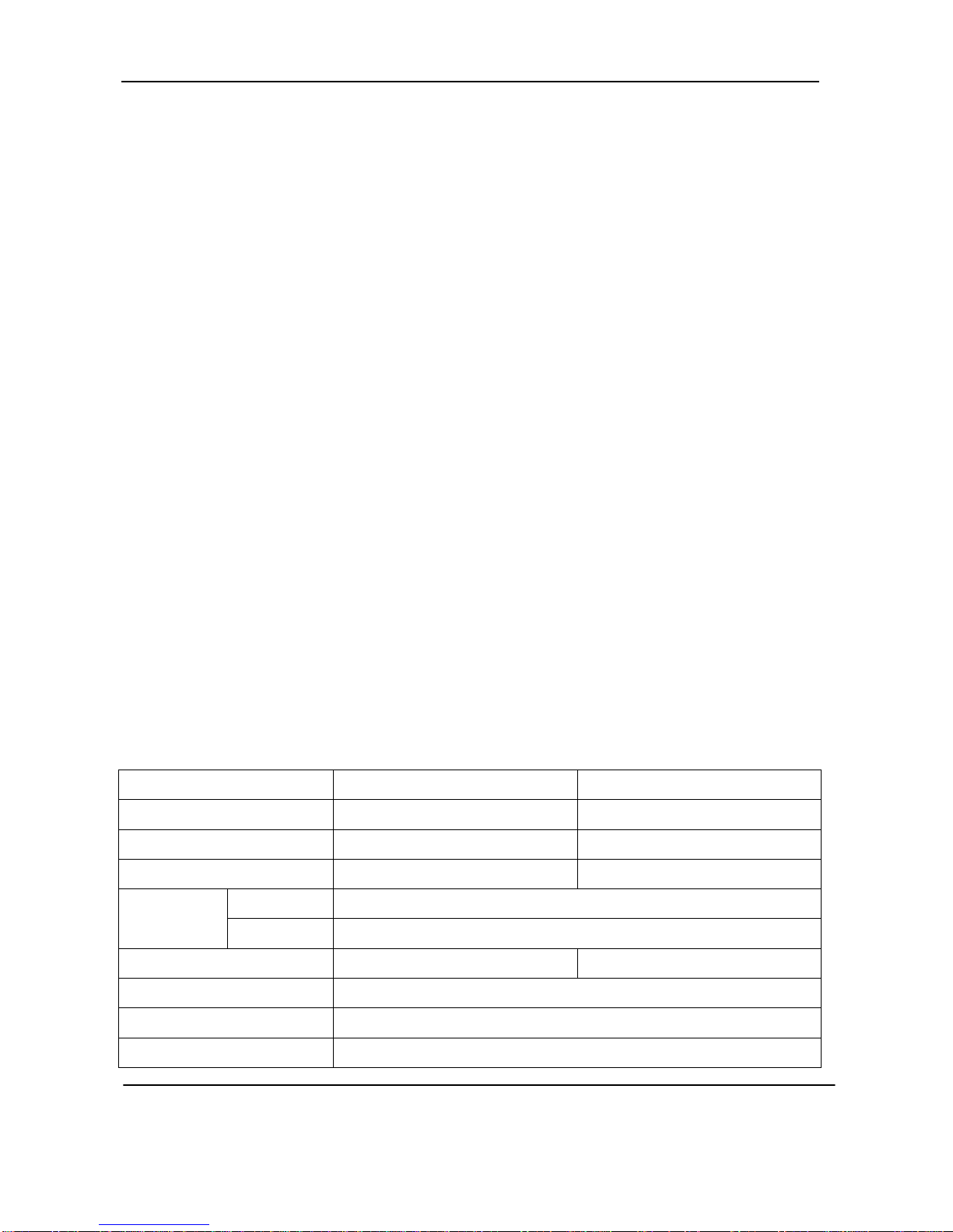
(1)If the machine’s oil pan has an oil sump, never operate the machine before filling it.
(2)If the machine is lubricated by a drop oiler, never operate the machine before lubricating.
(3)When a new sewing machine is first turned on, verify the rotational direction of the pulley with the
power on. (The pulley should rotate counterclockwise when viewed from the pulley)
(4)Verify the voltage and (single or three) phase with those given on the machine nameplate.
3)Precautions for operating conditions:
(1)Avoid using the machine at abnormally high temperatures(35 or higher℃)or low temperatures(5℃
or lower).
(2)Avoid using the machine in dusty conditions.
2.SPECIFICATIONS
Model GC20528-MDZA GC20528-BDZA
Max.sewing speed 4000r.p.m 3000r.p.m
Application Light weight Medium weight
Stitch length 0-5mm 0-7mm
Presser-foot
stroke
By hand 8mm
By pneumatic 16mm
Needle size DP×5 14# DP×5 21#
Lubrication Automatic lubrication
Motor 750W sevor motor
Needle gauge 6.4Standard

3.LUBR
I
1) Oilin
g(
Fill th
e
oil up to oil
should be p
e
If oil level i
s
replenish oi
l
Use white
2) Oilin
g(
When
a
is used for t
h
machine lef
t
considerabl
y
again,reple
n
of oil to the
Ad
j
ustme
n
3) Oilin
g
See dri
p
4.PREC
A
(1)
W
(2)It
during sewi
n
(3)Si
b
ox cover c
l
(4)D
o
control ci
r
voltage o
f
semiconduc
t
I
CATIO
N
(
1)
e
oil reservoi
r
level mark.
O
e
riodically c
h
s
found belo
w
l
to the oil
l
spindle oi
l
(
2)
a
new sewin
g
h
e first time,
o
t
out of use f
o
y
long time i
s
n
ish a suitabl
e
portions indi
n
t of oilin
g
condition
p
ping of oil
t
A
UTION
W
hen the pow
e
should be n
o
n
g machine
o
nce dust in t
h
l
ose during o
p
o
not apply
a
r
cuit for
f
multimert
e
t
or compone
n
N
r
with
O
il level
h
ecked.
w
the level
l
evel mark.
l
.
g
machine
o
r sewing
o
r
s
used
e
amount
cated by arr
o
g
to rotatin
g
t
hrough the o
S OPER
A
e
r is turned o
o
ted that the
b
o
peration.
h
e control b
o
p
eration.
a
multimete
r
checking,ot
h
e
r might
d
n
ts in the cir
c
o
w in the bel
o
g
hoo
k
.
il sight wind
o
A
TION
n or off,keep
b
rake may n
o
o
x might cau
r
to the
h
erwise
d
amage
c
uit.
— 2
—
o
w figure.
o
w to check
o
foot away f
r
o
t work whe
n
se malfuncti
o
—
o
iling condit
i
r
om the peda
l
n
the power i
s
o
n or control
i
on during o
p
l
.
s
interrupted
troubles,be
s
p
eration.
or power fai
s
ure to keep
lure occurs
the control

— 3 —
5.ADJUSTMENT OF NEEDLE BAR STOP POSITION
When the pedal is kicked down by heel,the machine stop at“UP”position.If the marks deviate larger than
3mm,adjust as follows:
Release the set screw of the magnet positioned piece, adjust the position of magnet positioning piece,
until the machine stops in the needle up position (the marker on the pulley and the reference line of motor
cover to coincide), then tighten the screws.
6.INSTALLING NEEDLE
Note:Before installing the needle,be sure
to turn off the power.
To install the needle, turn the machine pulley over
toward operator(or counter-clockwise)until the needle
bra moves up to its highest point,put the needle up into
the needle bar(or needle clamp) as deeply as it will
go,with the long groove of the needle face to face.Tighten the needle
set screw securely.
7.WINDING BOBBIN THREAD
Note:When bobbin thread is wound, keep the presser foot
lifted.
Thread tension:Particularly in the case of nylon or polyester
thread,wind the bobbin loosely.
(1)Press the bobbin onto the thread winding shaft.
(2)Pass the thread for winding thread as shown in the figure,
and wind the end of the thread clockwise around the bobbin several
times, then wind the thread on the thread adjuster side counter-clock
wise several times.
(3)Press lever 1 in the direction of the arrow, and start the
sewing machine.
(4)The operation will automatically stop when winding is completed.
(5)Adjustment of thread winding strength, adjust with the thread adjuster nut 2.
(6)Adjustment of thread winding amount, adjust by loosening screw 3 and moving adjustment plate 4:
The thread winding amount will increase when moved in the direction of a.
The thread winding amount will decrease when moved in the direction of b.

8.SELE
C
It is rec
o
from front),
use “Z”twi
s
thread as w
e
9.THRE
A
(1)P
a
Note:
W
show in fig
u
(2)T
h
Note:
P
C
TION
O
o
mmended t
o
and “Z”twis
t
s
t thread in
e
ll as “Z”twi
s
A
DING
a
ss each thre
a
W
hen thin s
l
u
re.
h
read take-u
p
P
ressing the
O
F THRE
A
o
use”S”twis
t
t
thread in th
both the ne
e
s
t thread can
b
a
d through th
r
l
ippery thre
a
p
lever to the
tension rele
a
A
D
t
thread in t
h
e right need
l
e
dles.For bo
b
b
e used.
r
ead guide A
.
a
d (polyeste
r
highest posit
a
sing handl
e
— 4
—
h
e left needl
e
l
e.When disc
r
b
bin thread,
”
.
r
thread) is
u
ion, pass eac
h
e
bar , the th
r
—
e
(viewed
r
iminate
”
S”twist
u
sed pass th
e
h
thread in t
h
r
ead can be
p
e
thread thr
o
h
e order in fi
g
p
ulled out e
a
o
ugh thread
g
ure.
a
sily.
guide B as

10.ADJ
U
Rotate t
h
When p
r
disappear.
11.SET
T
(1)P
u
(2)H
o
12.LIFT
I
(1)P
u
The th
r
(2)
W
By pul
l
b
obbin thre
a
U
STMEN
h
e stitch len
g
r
ess the fee
d
T
ING OF
u
lling out 5c
m
o
ld the bobb
i
I
NG TH
E
u
t the hook i
n
r
ead end sho
u
W
hile holding
l
ing up the n
e
a
d and needl
e
T OF ST
I
g
th adjusting
d
d
reversing l
e
BOBBI
N
m
thread tail
f
i
n so that the
E
BOBBI
N
n
to the bobbi
n
u
ld be left on
the thread b
y
e
edle thread,
e
thread shou
l
I
TCH L
E
d
ial to chang
e
e
ver, reverse
N
f
rom the bob
b
bobbin threa
d
N
THRE
A
n
case and pr
e
the bed.
y
left hand,ro
r
as shown in
t
l
d be aligned
— 5
—
E
NGTH
A
e
the stitch l
e
sewing will
b
in.
d
is would i
n
A
D
e
ss down the
r
ate the bala
n
t
he figure,th
e
and led bac
k
—
A
ND RE
V
e
ngth.
take place.
L
n
right directi
o
latch 1.
n
ce wheel on
e
e
bobbin thre
k
ward.
V
ERSE S
E
L
oose the le
v
o
n and put it
e
turn by rig
h
ad will be li
f
E
WING
v
er, reverse
s
into the hoo
k
h
t hand.
f
ted.The co
m
s
ewing will
k
.
m
bination of

— 6 —
13.BALANCE OF THREAD TENSION
14.ADJUSTMENT OF THREAD TENSION
There is virtually no need to adjust the bobbin thread
tension, except for special kind of the thread, when slight
adjustment will be necessary.
Turning the adjusting screw clockwise will increase the
tension of bobbin thread, otherwise, the tension of bobbin
thread will decrease.
Needle thread tension should be adjusted in reference to
bobbin thread tension.
To adjust needle thread tension,turn each tension adjusting
nut.
Needle thread tension can be also adjusted for special fabric and thread by changing intensity and movable
range of slack thread adjusting spring.
15.ADJUSTMENT OF PRESSER FOOT
PRESSURE
Pressure of presser foot is to be adjusted in accordance with
thickness of materials to be sewn.
First loosen lock nut. For heavy materials, turn the adjust bolt
to increase the pressure, while for light materials, turn the
adjust bolt to decrease the pressure as shown in Fig. After the
adjustment. Tighten the lock nut.

— 7 —
16.TIMING BETWEEN ROTATING HOOK MOTION AND NEEDLE
MOTION
(1)Set the stitch length on the stitch length dial shown
table.
(2)When the needle is lifted Ashown table, from the lowest
position, as shown in Fig. The following positional relationship
should be maintained:
a.The lower edge of needle eye should be 1.0-1.6mm below
the hook point.
b.The hook point should be located the center of the needle
axis.
c.Gap between the hook point and the side face of needle
should be 0.05mm.
Note:Positioning of hook point
(1)When the needle is at DOWN position,the smaller gear
should be engaged with the large gear so that the “S”screw of the
latter gear on the reverse side.
(2)Tighten each “S”screw,where is punched for set screw,on
the hook shaft.
(3)Approximate position of hook “C”screw of hook should
be found close to the needle when the needle is at DOWN position.
To finely adjust timing between the needle motion and hook
motion,loosen the set screw of large gear and move the hook saddle
in lower shaft axial direction within a rang from 1mm to 2mm.
Note:Position adjustment of needle point
Adjust needle position so that gap between the lower edge of needle is 1.0-1.6mm when the needle is lifted
by A mm from its lowest position.
Model GC20528-MDZA GC20528-BDZA
Stitch length 3 4.5
Needle lift A 2.2mm 2.4mm

17. N
E
Note:
T
(1)
S
(2)
S
(3)
18. R
E
(1
(
2
(3
E
EDLE
B
T
he stopper
w
sewing Ma
c
adjust whil
e
position.
S
top the mot
i
Make the st
o
S
top the mot
i
Make
t
Two needles
Press
d
restore to O
E
LATIO
N
)Determine
t
2
) The needle
) Example:
W
B
A
R
STO
P
w
rench can b
e
c
hine running
e
Take-up lev
e
i
on of left-si
d
o
pper wrenc
h
i
on of right-s
t
he stopper
w
running at t
h
d
own restore
p
position aut
o
N
S BET
W
t
he stitch len
g
number of a
n
W
hile the an
g
P
POSIT
I
e
operated w
h
, but the bes
t
e
r stopping a
t
d
e needle bar
h
to the posit
i
ide needle b
a
w
rench to the
p
h
e same time:
p
late, stoppe
r
o
matically.
W
EEN C
U
g
th accordin
g
n
other outsi
d
g
le is 40°, if t
h
— 8
—
I
ON (LE
F
h
ile the
t
way is to
t
its highest
:
i
on L.
a
r:
p
osition R.
r
wrench
U
RVE A
N
g
to the form
t
d
e needle can
h
e stitch is 2.
—
F
T & RI
G
N
GLE AN
t
o obtain var
i
be obtained
w
9mm, then t
h
G
HT)
D STIT
C
i
ous.
w
hile the an
g
h
e outside ne
e
C
H LEN
G
g
le
b
e determ
i
e
dle number
G
TH
i
ned.
is 6.

— 9 —
19.ADJUSTMENT OF FEED DOG HEIGHT
Height of feed dog and pressure of presser foot should be adjusted for
individual fabric(s) with the following cautions:
(1)Fabric will be damaged if the feed dog extends too high,or pressure
foot is too large.
(2)Even stitch length cannot be assured if the feed dog is too low or
pressure foot is too small.
(3)Feed dog height should be measured at the point where the needle is
at the top position.
For light fabrics: Approx. 0.8mm from throat plate
For usual fabrics: Approx. 1.0mm from throat plate
For heavy fabrics:Apporx.1.2mm from throat plate
Adjustment procedure
a.Lean the machine head backward.
b.Turn the pulley by hand and stop when the feed dog rises to the
maximum height.
c.Loosen the feed bar set screw.
d.Vertically move the feed bar(in the direction indicated by arrow in the
figure)to adjust it to adequate height.
e.After the adjustment,tighten the feed bar set screw.
The feed dog height is factory-adjusted to 1.0mm.
20.RELATIONSHIP BETWEEN ROTATING HOOK MOTION AND
TAKE-UP LEVER MOTION
When the timing belt was removed for its replacement,for
example,the relationship between relating hook motion and
take-up lever motion should be adjusted as follows:
(1)Turn the balance wheel and stop when the take-up
lever is lifed to its upper dead point.
(2)Lean the machine head backward and make sure
the arrow(timing mark)put on the timing belt is in line with
the black line on the boss of lower shaft.
(3)If the timing mark is not in the line with the black,
remove the timing belt and install it again to adjust.

— 10 —
21.RELATIONSHIP BETWEEN HOOK MOTION AND OPENER MOTION
(1)Turn the balance wheel by hand and stop when
the opener holder is located most remotely from the
throat plate.
(2)Make sure the gap between the bobbin case
holder A and the opener is approximately 0.2mm.
(3)If the gap is too large or small,loosen the
opener holder set screw B and adjust position of the
opener.
22.RELATIONSHIP BETWEEN NEEDLE MOTION AND FEED DOG
MOTION
(1)Set feed length to “0”on the feed setting dial.
(2)Lean the machine head backward.
(3)Loosen the feed lifting rock shaft crank set screw
A and B.
(4)Set the needle at the lowest position.
(5)Adjust the distance between presser rod and
vibration prevention rod to 13.5mm and temporarily tighten
the feed lifting rock shaft crank set screws A and B.
(6)If the connection is not at right angle,remove the back cover,loosen screw C and move the right link to
adjust.
(7)After the completion of adjustment,fully tighten the screw A,B,C.
Note:At the same time make certain that needle can enter the feed dog needle hole at the center of
the hole.

— 11 —
23.SAFETY CLUTCH DEVICE
Safety clutch device is installed to prevent the hook and cog belt from
damage in case the thread is caught into the hook when the machine is
loaded abnormally during operation.
1) Function of safety clutch
(1)When the safety clutch acts,the belt pulley will be unloaded,then
the rotation of hook shaft will stop.The arm shaft only will rotate.Stop the
operation of machine.
(2)Clean the thread thoroughly which is caught into the hook.
(3)Turn the pulley bushing by hand,and check whether the hook shaft rotates lightly and properly,place
the clutch device as follows.
2) How to set the safety clutch
(1)While pressing down the push button on the
opposite side of bed by left hand,turn the balance wheel
slowly by right hand away from you as shown in the figure.
(2)The balance wheel will stop by the gear plate,but
turn the balance wheel more firmly.
(3)Release the push button.
(4)As shown in the figure,the safety clutch device is
set.
3) Force applied to the safety clutch
(1)The force applied to the safety clutch is the
smallest when the white mark of the eccentric pin faces the
center of the lower shaft.The force proportionally increase
as the white mark faces the outside.
(2)To adjust the force slide the timing belt,loosen
the set screw,and turn the eccentric pin.
After the adjustment,make sure to tighten the set screw.

— 12 —
24.ADJUSTMENT OFTHE UPPER FEED
If the uneven feeding occurs according to the fabric.Adjust the long hole of the horizontal feed shaft
crank(right)to adjust the upper feed length.Adjust as follows:
(1)Loosen the bolt.
(2)Move the bolt upward to increase upper feed.
(3)Move the special bolt downward to decrease the upper feed.The upper feed and the lower feed
theoretically becomes equal at the reference line on the feed connection crank(right).
Securely tighten the bolt after adjustment.
25. ADJUSTMENT THE STITCH TOLERANCE
Screwing the pin that connects the link of back-sewing with the crank of back-sewing(down)can adjust the
tolerance of between the stitches.Screwing the pin in clockwise can increase the stitch of forward
sewing,otherwise,the stitch of back-sewing will be increased.

— 13 —
26.INSTALLATION OF MOVABLE KNIFE
1) Installation of movable knife
(1)Turn the balance wheel and lower the needle bar to the lowest position.
(2)Push the cam follower crank so that the cam roller enters into the thread trimmer cam groove.
(3)Turn the balance wheel until the black mark point on the arm meets the white mark point on the
balance wheel.Set the cam follower crank at this position with a screwdriver temporarily preventing the cam
roller coming out from the cam groove.
(4)Loosen the thread trimmer rocking crank clamp boltsA and B.
(5)Adjust the movable knife so that the movable knife end slant portion protrudes 0-0.5mm from the
fixed knife,as shown in figure and tighten the bolts Aand B.
2) Gap between movable knife and bobbin case holder stopper
(1)Turn the balance wheel by hand until needle reaches the lowest position.
(2)With the needle at the lowest position,depress cam follower crank,turn the balance wheel until the
movable knife reaches the extremity of its stroke.
(3)Manually rotate the inner hook in the direction indicated by arrow in figure and adjust gap between
the movable knife and the inner hook stopper to about 0.5mm(the screws A and B should be loosen for this
adjustment).

— 14 —
27.ADJUSTMENT OFTHREAD TRIMMER CAM
(1)Turn the balance wheel by
hand until the needles reach the lowest
position.
(2)Maintaining the needle
position,depress the cam follower
crank and put the cam roller into the
groove of thread trimmer cam.
(3)Turning the balance wheel
by hand,adjust the thread trimmer cam
so that the movable knife starts
moving when the green mark point on the balance wheel
comes in line with the black mark point on the arm.
Note:To adjust,loosen two thread trimmer cam clamp
screws A.
28.ADJUSTMENT OF SCISSORING PRESSURE OF MOVABLE KNIFE
AND FIXED KNIFE
(1)Loosen the fixed knife bracket clamp bolt A.
(2)Turn the vertical position adjusting screw B to adjust meshing
pressure and then righter the hexagon socket head cap screw A.
Note:Since excess pressure cause large torque to the thread
trimming mechanism and trimming failure,adjust it so that thread
can be trimmed with minimum pressure.
(3)Move the movable knife and check that the thread can be
sharply trimmed.
29.SHARPING OF FIXED KNIFE
When the knives dull,the fixed knife should be sharpened as illustrated in figure.Since it is very difficult to
sharpen the movable knife,replace it with a new one when it dulls.

— 15 —
30.ADJUSTMENT FOR CHANGE OF NEEDLE GAUGE PARTS
(1)Replace the throat plate, feed dog and needle clamp.(Since the throat plate and feed dog are special
parts designed for thread trimming machine, be sure to use those specified by us.)
(2)Lean the machine head backward.
(3)Loosen two connecting link clamp bolts J.
(4)Remove the spring M.
(5)Loosen the hook bracket clamp screws A and B and adjust gap between each needle and hook.
(6)When the needles and hooks have been adjusted, install the spring M.
(7)Contact the rocking cranks C and D to the stopper pins E and F and tighten the connecting link clamp
bolt J.
(8)Turn the balance wheel by band until the needles reach the lowest position.
(9)Loosen the nuts G and H.
(10)Depress the cam follower crank K and adjust the connecting rod L so that the cam roller can
smoothly enter the groove of thread trimmer cam.
(11)Adjustment of the cam groove and the cam roller
a.Push the cam follower crank K so that the cam roller enters into the cam groove.
b.Turn the connecting rod L and adjust the clearance between the cam roller and the cam groove surface N
as small as possible, and tighten the nuts G and H.
c.Push the cam follower crank K again and check that the cam roller enters into the thread trimmer cam
groove smoothly.

— 16 —
31.SPECIFICATIONS OF THE OPERATION PANEL
The operation panel is integrated with the motor cover.The operation panel LCD module will display the
sewing mode,specifications,bartacking,foot lifting,needle stop position,thread trimmer and low-speed start. Each
key on the operation panel diagram as shown. (Left : standard control operation panel Right : integrated
control operation panel)
32.VALVE COMPLETE
This machine is designed with mini valve complete that installed integrately by several valves. The function
of the valves as shown in Fig.(Left: standard control system.Right :integrated control system)
C.Feed reversing D.Presser foot lifting E.Thread tension releasing
Bartacking
(
ON/OFF
)
Bartacking
(ON/OFF)

上 海 标 准 海 菱 缝 制 机 械 有 限 公 司
SHANGHAI BIAOZHUN HAILING SEWING MACHINERY CO., LTD.
地址: 上海市松江区书林路850号
ADD: 850, Shulin Road, Songjiang District Shanghai, P.R.China
邮编: 201612
Zip Code: 201612
内销业务:电话: 86-21-64061284 传真: 86-21-64462799
零件服务:电话: 86-21-64851424 传真: 86-21-64069792
Overseas Business: TEL: 86-21-64853303 FAX: 86-21-64854304
ADD:RM105,Bld.5 Yuan Zhong Industry Park, No.2007 Hongmei Road,
Shanghai, P.R.China 201103
制造商保留因技术改进而更改内容的权利,恕不另行通知
2017年12月印制
This manual suits for next models
1
Table of contents
Popular Sewing Machine Accessories manuals by other brands

DeLuxe Stitcher
DeLuxe Stitcher 26D Operation and maintenance manual

ELNA
ELNA 202-084-206 quick start guide

handi quilter
handi quilter TruStitch user manual

Janome
Janome 202297008 instructions

Janome
Janome Quilt Maker Pro 5' Quilting Frame Assembly instructions

Racing
Racing MDK 60 Series Instructions and parts manual