Highway Equipment Company NEW LEADER G4 User manual

HIGHWAY EQUIPMENT COMPANY - NEW LEADER DIVISION
1330 76th AVE SW, CEDAR RAPIDS, IOWA 52404-7052
PH. (319) 363-8281 www.highwayequipment.com FAX (319) 632-3081
HIGHWAY EQUIPMENT COMPANY
G
4
HOW TO
CHECK YOUR
G4 SPREAD PATTERN

G4 SPREAD PATTERN
UNIT SERIAL NUMBER__________________
MANUAL NUMBER: 305438-SP-A
EFFECTIVE 01/2008
HIGHWAY EQUIPMENT COMPANY
1330 76TH AVE SW
CEDAR RAPIDS, IOWA 52404-7052
PHONE (319) 363-8281 FAX (319) 632-3081
www.highwayequipment.com
BUILDING THE BEST SINCE 1939
3
HIGHWAY EQUIPMENT COMPANY
G
4
305438-SP-A
Page Rev. A
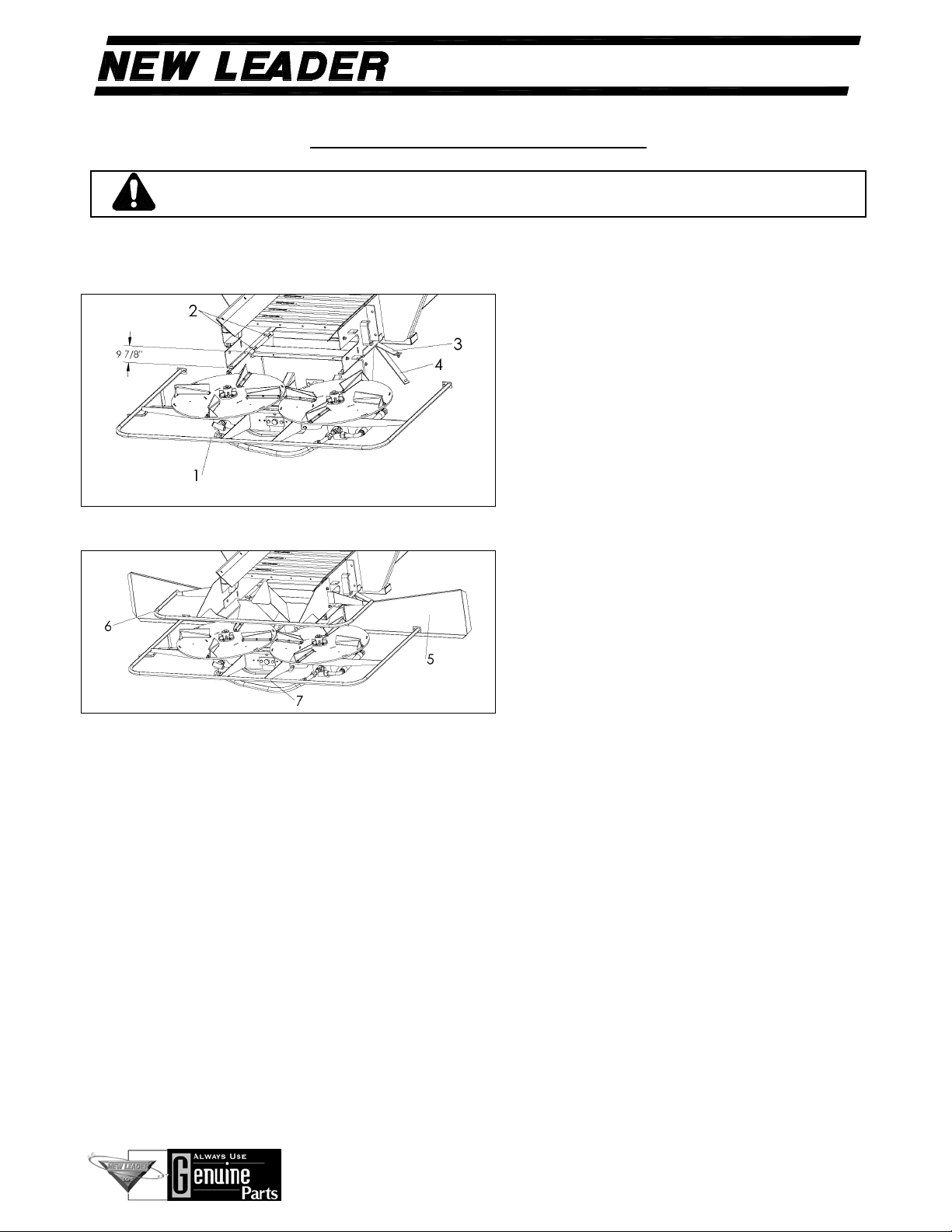
SPINNER ASSEMBLY INSTALLATION
WARNING Keep spinner assembly supported until mounting is complete. Never
exceed workload limits or use slings to lift items over people.
Use the following instructions when installing a G4 Spinner Assembly on a New Leader L5034 G4
spreader:
*9 7/8 = 25.08cm
1. Use a suitable lifting device to hoist the
spinner assembly (Item 1 - Figure A) onto
the rear of the sills. Note: The spinner
assembly weighs approximately 500 lbs.
(154 kg) Align the spinner assembly holes
with the sill holes. Insert four carriage bolts
(Item 2) through holes, place shield brackets
(Item 3), then stiffener bars (Item 4) on front
bolts and attach with washers, lock washers
and nuts. Hand-tighten only. Remove the
two wooden 2 x 4’s (5.08cm x 10.16cm) and
hardware used during shipping.
2. Make sure the spinner assembly is square.
Measure from the spinner mounting bracket
that sits on the sill to the end of the sill on
both sides. The distance should be
approximately 9-7/8” (25.08cm) on each
side as shown in Figure A. Center the
spinner assembly from side-to-side by
measuring from the spinner hub to the sill
on each side—these two measurements
should be equal. Tighten the rear bolts
securely.
Figure A – Spinner Assembly Installation
Figure B – Shield Installation
3. See Figure B. Install the right-hand (Item 5) and left-hand (Item 6) spinner shields on the spinner
assembly and attach the shield brackets (Item 3) and stiffener bars (Item 4) to the shields using
hardware provided. Attach the spinner guard (Item 7) both spinner shields with hardware provided.
Tighten all shield hardware securely, including the front bolts of the spinner assembly.
4. Install the pressure, return and case drain hoses. Crank the spinner assembly all the way forward
and back to make sure the hoses and fittings do not interfere with the spinner assembly as it moves.
Tie all loose areas of hose together with wire ties to prevent contact with moving parts during
operation.

4
HIGHWAY EQUIPMENT COMPANY
G
4
305438-SP-A
Page Rev. A
SPINNER ASSEMBLY INSTALLATION CONTINUED
LH RH
5. Make sure the fins are installed on the
spinner discs correctly. Position all fins in
the position 2 as shown in Figure C.
6. Set spinner RPM at 550-575 for compost
initially. These settings can be found using
the controller in the cab. The spinner
sensor will measure the spinner’s speed.
Figure C – Fin Location for 34” Conveyors
7. Slide the slots of the material divider (Item
8) onto both sills so material divider’s
mounting tab rests on sills’ flanges. Align
two holes on outside of each sill with
material divider holes, insert capscrews
and loosely attach washers, lock washers
and nuts. Secure mounting tab to sill’
flanges with capscrews, lock washers and
nuts. Tighten all hardare.
Figure D – Material Divider Installation

5
HIGHWAY EQUIPMENT COMPANY
G
4
305438-SP-A
Page Rev. A
ADJUSTING THE SPREAD PATTERN
NOTICE!
Spinner assembly has NOT been adjusted at the factory. Before spreading
material, spread pattern tests must be conducted to properly adjust the spread
pattern. A Spread Pattern Test Kit, part number 300508, is available for this
purpose. THE MANUFACTURER OF THIS SPREADER WILL NOT BE
LIABLE FOR MISAPPLIED MATERIAL DUE TO AN IMPROPERLY
ADJUSTED SPREADER!
It is recommended that spread pattern tests be conducted prior to each spreading season, after any
spreader maintenance, and periodically during the spreading season. Spread pattern tests must be
performed for each product and application rate.
Spread pattern is affected by many factors. Among the more significant of these are:
1. Spinner speed.
2. Material weight per cubic foot.
3. Material flow characteristics.
4. Rate of delivery of material.
5. Point of delivery of material on spinner discs.
6. Balance between deliveries to both spinner discs.
7. Angle of the distributor fins on the spinner discs.
8. Cleanliness of the spinner fins and discs.
9. Level of spreader.
10. Wind and humidity.
11. Spacing of swaths.
12. Wear on spinner fins.
Since many of these factors will vary for each job, trial and experience must be used to determine the
adjustments which must be made to obtain the spread width and spread pattern desired. The following
instructions are given to cover the adjustments available and the effect that each will have on the spread
pattern.

6
HIGHWAY EQUIPMENT COMPANY
G
4
305438-SP-A
Page Rev. A
ADJUSTING THE SPREAD PATTERN CONTINUED
SPINNERS
WARNING
Use great caution while working around the spreader. Contact with
spinners and other moving parts is very dangerous. Do not adjust
while machinery is moving, wear eye protection and avoid discharge
from spinners. Do not ride on moving spreader.
NOTICE! Spinner discs and fins must be kept clean and polished. Even a small build-up
on a spinner fin can significantly affect the spread pattern. Rusty, rough, bent
or worn fins will produce poor spread patterns.
Fan speed is adjustable from approximately 350 to 680 RPM. This is accomplished by changing the
settings in the controller.
Proper fan speed adjustment is very important in obtaining good spread patterns. The best fan speed to
use will depend entirely on the material being spread, and must be determined by testing.
Pattern width will vary anywhere from 25 to 55 feet.
For every material there is a critical fan speed. In other words, there is a speed which will result in the
maximum width obtainable. Going beyond this speed will not increase spread width, but will result in
poor patterns.
Too high a fan speed could result in a heavy deposit behind the truck due to break-down of material.
This upper speed limit will be quite low for finely powdered material, and can be quite high for
extremely coarse materials. In general, this critical speed will fall somewhere between 550 and 575
RPM for ordinary materials.
One way to adjust fan speed is to watch the material leaving the fans. At slow speed the material leaves
the blades in narrow bands. At medium speed it forms wide bands in the air. At somewhat higher
speed, the bands close into a uniform blur. Normally, the proper fan speed is slightly higher than that
when the bands close to a blur.

7
HIGHWAY EQUIPMENT COMPANY
G
4
305438-SP-A
Page Rev. A
TEST EQUIPMENT AND PROCEDURES
It is recommended that a spread pattern test be performed for each product and application rate you
handle. Once initial testing is completed, testing should be repeated at the beginning of every season,
or any time maintenance is performed on any component affecting spread patterns.
SPREAD PATTERN TEST KIT
PART NO. DESCRIPTION QTY PART NO. DESCRIPTION QTY
300508 Spread Pattern Test Kit,
includes the following:
70890 Collection Tray 21 99418 Data Sheets 100
87200 Divider 21 300503 Screw – #6-32 x 3/8 42
300506 Rack – Tube 1 300504 Nut – Lock #6-32 42
300507 Test Tubes 21 70897 Flags 5
300505 Clip – Molded 21 87199 Rope – 120’ marked 1
87332 Funnel 1 87201 Stakes 2
Note: Larger containers will be needed.
SPREADER PREPARATION
The spreader to be tested shall be in good mechanical condition and properly adjusted according to the
Operation and Maintenance Manual.
All damaged and worn parts must be replaced. Spinner discs and blades must be free of any material
build-up, rust or paint.
Fill the hopper with the material to be spread. Run the material out to the end of the conveyor.
Set the feedgate to deliver the required rate per acre. Make sure the feedgate is level and the indicator
reflects the actual gate opening measured by standing a tape measure vertically in the fertilizer.
Adjust the spinner assembly by turning the crank. To begin testing, position the spinner at 3.5 for
compost.
8
HIGHWAY EQUIPMENT COMPANY
G
4
305438-SP-A
Page Rev. A
TEST EQUIPMENT AND PROCEDURES CONTINUED
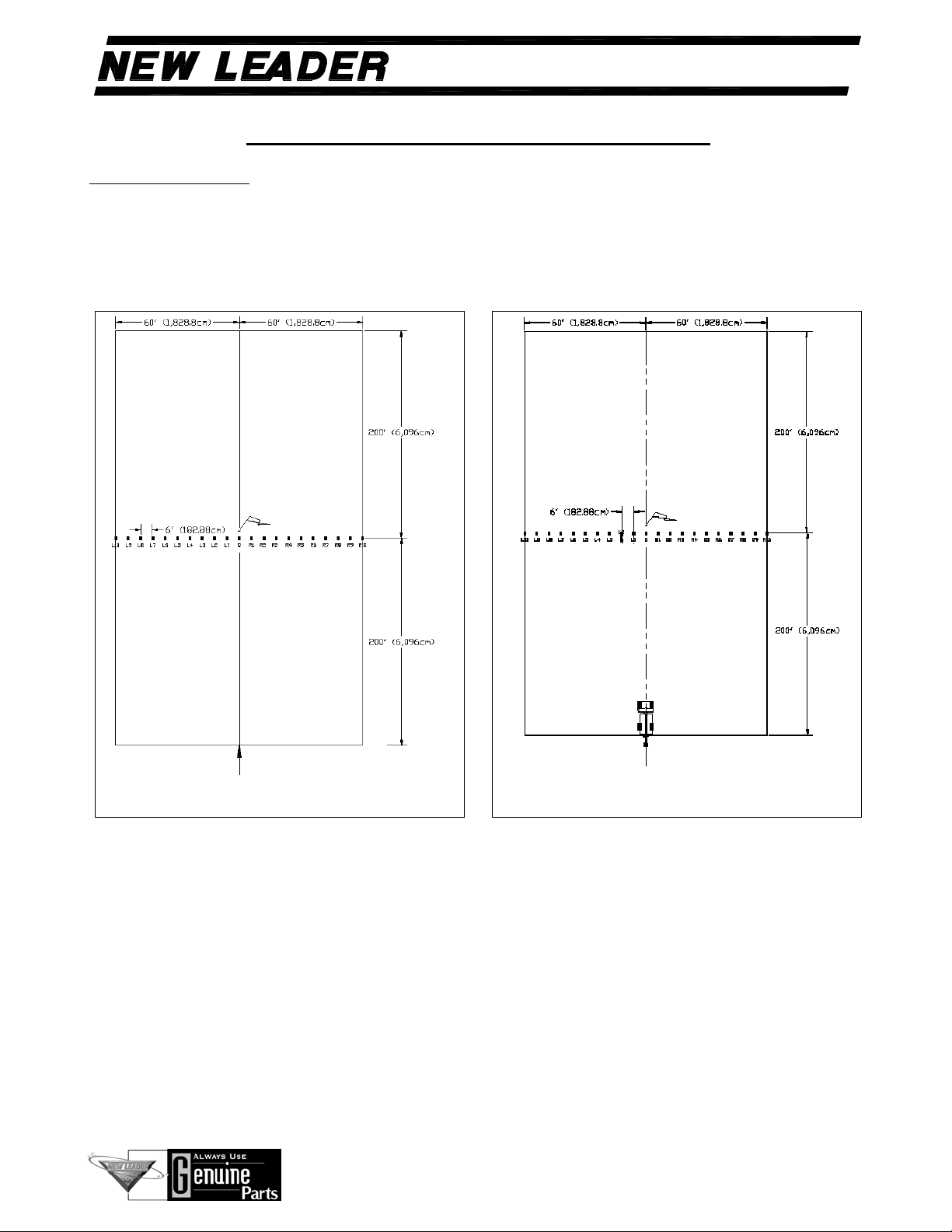
TEST PROCEDURE
The area selected for testing, measuring 120 feet x 400 feet (3,657.6cm x 12,192cm), should have a
slope of less than two degrees.
Insert a plastic grid into each of the 21 collection trays. Position the 21 collection trays on six-foot (6’)
(182.88cm) centers with the longest dimension of the tray parallel to the direction of travel. (Figure E)
DIRECTION OF TRAVEL
COURSE SET UP FOR PATTERN TEST
DIRECTION OF TRAVEL
COURSE SET UP FOR PATTERN TEST
Figure E – Tray Positions Figure F – Spreader Position

9
HIGHWAY EQUIPMENT COMPANY
G
4
305438-SP-A
Page Rev. A
TEST EQUIPMENT AND PROCEDURES CONTINUED
All testing should be done when the wind velocity is less than 5 MPH. If wind is present, testing must
be done with spreader traveling parallel (within ±15 degrees) to the wind direction.
Do not allow loaded spreader to sit for more than four hours prior to testing.
Prior to driving the spreader through the test course, it should be driven at least 450 feet (13,716cm) at
spreader test speeds.
Spreader must be driven over the collection trays in ONLY ONE DIRECTION.
Position spreader at the beginning of the course so that vehicle will straddle center collection tray.
(Figure F) Set gate opening based on desired rate/acre according to theoretical application charts
supplied with each unit.
Drive spreader completely through course at normal operating speeds.
DATA RECORDING
Using the data sheets supplied with the kit, document all spreader adjustments required.
Using the funnel, transfer the contents of each collection tray into its corresponding test tube beginning
at one end of the trays and working towards the opposite end.
Record the volume in each test tube in the box on the data sheet under the corresponding tray position.
(Figure G) NOTE: It is highly recommended that ONLY ONE ADJUSTMENT be made between test
samples taken. If more than one adjustment is made, it will be difficult to determine which adjustment
was responsible for the change in pattern shape.

10
HIGHWAY EQUIPMENT COMPANY
G
4
305438-SP-A
Page Rev. A
TEST EQUIPMENT AND PROCEDURES CONTINUED
Figure G – Spread Chart Example
11
HIGHWAY EQUIPMENT COMPANY
G
4
305438-SP-A
Page Rev. A
TEST EQUIPMENT AND PROCEDURES CONTINUED
Once you attain a desirable pattern (Figure K), optimum-driving centers can be determined. To
determine optimum driving centers (effective swath width), locate the points on both the left and right
side of the pattern where the amount of material applied is half the amount at the center of the pattern.
The distance between these two points represents the driving centers to be used.
When blended fertilizers are being applied, a visual inspection of the samples should be made to
determine whether the blend within the effective swath width is consistent with the desired blend. If
the blend is not consistent, a narrower overall swath width should be used and a new optimum driving
center (effective swath width) should be determined.
Once the effective swath width has been established, a change in the processor may be required.
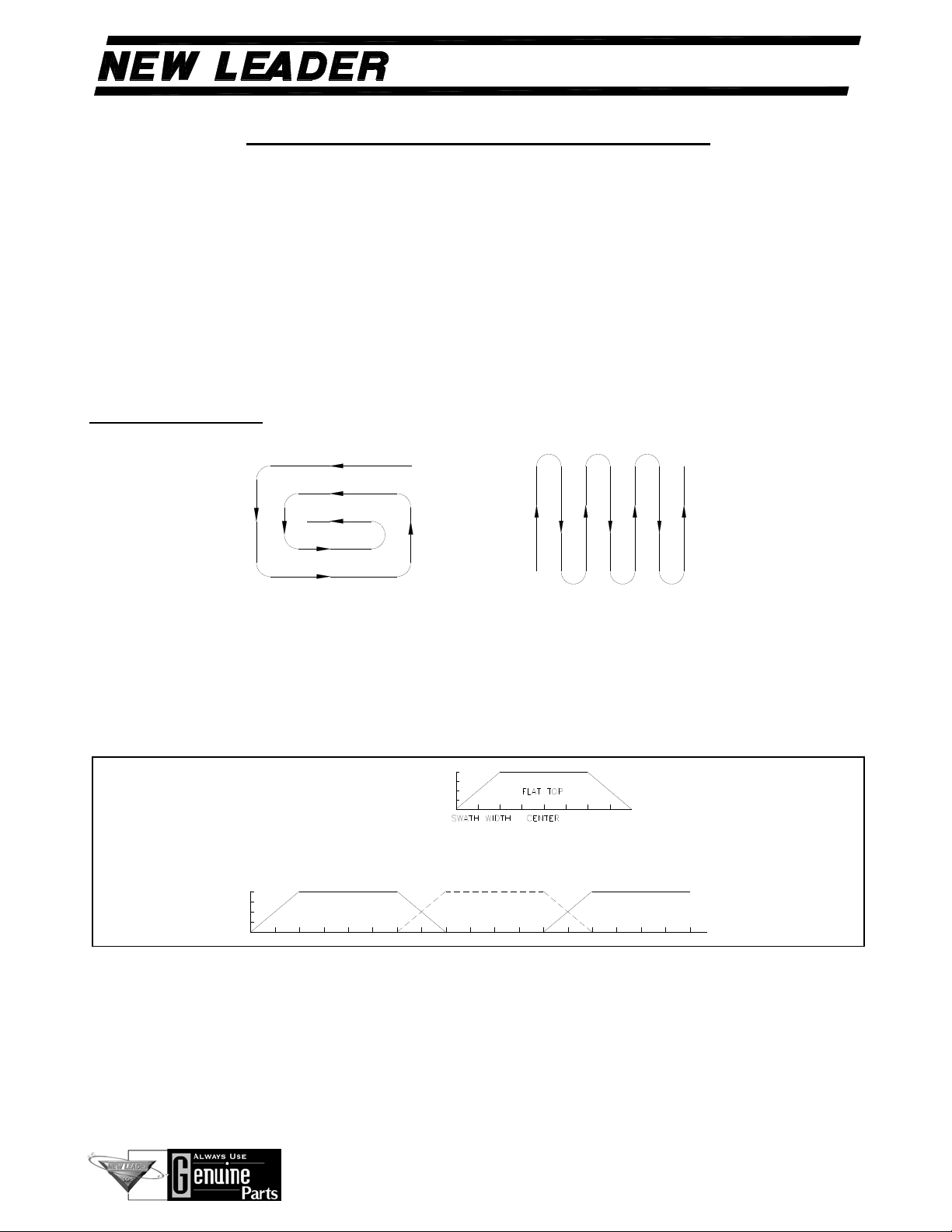
DRIVING METHODS
Figure I – Perimeter Method Figure J – Switch Back Method
The perimeter (Figure I) and switch back (Figure J) driving methods are both acceptable.
NOTE: Utilizing the switch back method amplifies non-symmetrical patterns by blending right side on
right and left side on left. The perimeter method compensates for non-symmetrical patterns by
blending the right side of the pattern with the left side of the adjacent pattern or vice versa.
FLAT TOP
IDEAL PATTERN OVERLAP
Figure K – Ideal Pattern

12
HIGHWAY EQUIPMENT COMPANY
G
4
305438-SP-A
Page Rev. A
TROUBLESHOOTING
PROBLEMS PATTERNS RECOMMENDED ADJUSTMENTS
Heavy Directly
Behind the Vehicle
RATE/ACRE
1. Move the spinner forward (toward the
conveyor).
2. Decrease spinner RPM.
3. Move one or two spinner blades to a
lower numbered hole.
Light Directly
Behind the Vehicle
1. Move the spinner rearward (away
from conveyor).
2. Increase spinner RPM.
3. Move one or two spinner blades to a
higher numbered hole.
Pattern Off Center
1. Check to see feedgate is level and free
of caked material.
2. Check to make sure individual spinner
speeds are equal.
3. Check to be sure spinner assembly is
mounted squarely and centered.
4. Testing should be done parallel to
wind.
Table of contents
Other Highway Equipment Company Spreader manuals


