manuals.online logo
Brands
  1. Home
  2. •
  3. Brands
  4. •
  5. HIK VISION
  6. •
  7. Keypad
  8. •
  9. HIK VISION DS-PKA-WLM-868 User manual

HIK VISION DS-PKA-WLM-868 User manual

COPYRIGHT ©2019 Hangzhou Hikvision Digital Technology
Co., Ltd.
ALL RIGHTS RESERVED.
Any and all informaon, including, among others, wordings,
pictures, graphs are the properes of Hangzhou Hikvision
Digital Technology Co., Ltd. or its subsidiaries (hereinaer
referred to be “Hikvision”). This user manual (hereinaer
referred to be “the Manual”) cannot be reproduced,
changed, translated, or distributed, parally or wholly, by
any means, without the prior wrien permission of
Hikvision. Unless otherwise spulated, Hikvision does not
make any warranes, guarantees or representaons,
express or implied, regarding to the Manual.
About this Manual
This Manual is applicable to Alarm Keypad.
The Manual includes instrucons for using and managing
the product. Pictures, charts, images and all other
informaon hereinaer are for descripon and explanaon
only. The informaon contained in the Manual is subject to
change, without noce, due to firmware updates or other
reasons. Please find the latest version in the company
website (hp://overseas.hikvision.com/en/).
Please use this user manual under the guidance of
professionals.
Legal Disclaimer
TO THE MAXIMUM EXTENT PERMITTED BY APPLICABLE LAW,
THE PRODUCT DESCRIBED, WITH ITS HARDWARE, SOFTWARE
AND FIRMWARE, IS PROVIDED “AS IS”, WITH ALL FAULTS AND
ERRORS, AND HIKVISION MAKES NO WARRANTIES, EXPRESS
OR IMPLIED, INCLUDING WITHOUT LIMITATION,
MERCHANTABILITY, SATISFACTORY QUALITY, FITNESS FOR A
PARTICULAR PURPOSE, AND NON-INFRINGEMENT OF THIRD
PARTY. IN NO EVENT WILL HIKVISION, ITS DIRECTORS,
OFFICERS, EMPLOYEES, OR AGENTS BE LIABLE TO YOU FOR
ANY SPECIAL, CONSEQUENTIAL, INCIDENTAL, OR INDIRECT
DAMAGES, INCLUDING, AMONG OTHERS, DAMAGES FOR
LOSS OF BUSINESS PROFITS, BUSINESS INTERRUPTION, OR
LOSS OF DATA OR
Trademarks Acknowledgement and other
Hikvision’s trademarks and logos are the properes of
Hikvision in various jurisdicons. Other trademarks and
logos menoned below are the properes of their
respecve owners.
DOCUMENTATION, IN CONNECTION WITH THE USE OF THIS
PRODUCT, EVEN IF HIKVISION HAS BEEN ADVISED OF THE
POSSIBILITY OF SUCH DAMAGES.
REGARDING TO THE PRODUCT WITH INTERNET ACCESS, THE
USE OF PRODUCT SHALL BE WHOLLY AT YOUR OWN RISKS.
HIKVISION SHALL NOT TAKE ANY RESPONSIBILITES FOR
ABNORMAL OPERATION, PRIVACY LEAKAGE OR OTHER
DAMAGES RESULTING FROM CYBER ATTACK, HACKER
ATTACK, VIRUS INSPECTION, OR OTHER INTERNET SECURITY
RISKS; HOWEVER, HIKVISION WILL PROVIDE TIMELY
TECHNICAL SUPPORT IF REQUIRED.
SURVEILLANCE LAWS VARY BY JURISDICTION. PLEASE CHECK
ALL RELEVANT LAWS IN YOUR JURISDICTION BEFORE USING
THIS PRODUCT IN ORDER TO ENSURE THAT YOUR USE
CONFORMS THE APPLICABLE LAW. HIKVISION SHALL NOT BE
LIABLE IN THE EVENT THAT THIS PRODUCT IS USED WITH
ILLEGITIMATE PURPOSES.
IN THE EVENT OF ANY CONFLICTS BETWEEN THIS MANUAL
AND THE APPLICABLE LAW, THE LATER PREVAILS.
Product Information
1
24
5
3
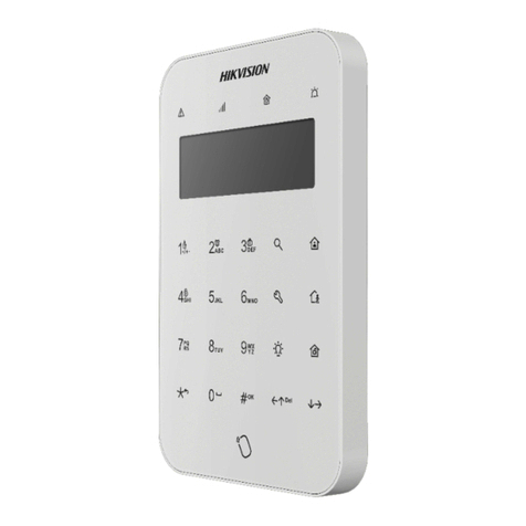
Wireless Alarm Keypad
This product and - if applicable - the supplied
accessories too are marked with "CE" and comply
therefore with the applicable harmonized European
standards listed under the RE Direcve 2014/53/EU,
the EMC Direcve 2014/30/EU, the LVD Direcve
2014/35/EU, the RoHS Direcve 2011/65/EU.
2012/19/EU (WEEE direcve): Products marked
with this symbol cannot be disposed of as unsorted
municipal waste in the European Union. For proper
recycling, return this product to your local supplier
upon the purchase of equivalent new equipment, or
dispose of it at designated collecon points. For
more informaon see: www.recyclethis.info
The Input voltage should meet both the SELV (Safety
Extra Low Voltage) and the Limited Power Source
according to the IEC60950-1 standard. Please refer
to technical specificaons for detailed informaon.
Tamper Screw
1
2
3
4
5
2
3
1
1
3
21
Control
Panel
Do not mix baeries of
different brands.
Do not mix old and new
baeries.
EN50131-1:2006+A2:2017
EN50131-3:2009E
N50131-5-3:2017
Security Grade 2
Environmental Class II
Present
Beep
Tag Sensed
Present Remove
Beep
Tag Sensed Hold 3s,
remove aer a beep
1
2
Present
Beep
Tag Sensed
3System
Armed
Remove
3 failed aempts
(different unregistered
tag or different
password) will cause
the keypad lock (90 s).
Refer to the Components
and Indicaon
secon for indicator and
buzzer descripon.
3. Secure the mounng plate on the wall with four supplied screws.
4. Rotate the keypad body clockwise to fasten the body on the plate.
1. Loosen the set screws on boom of the keypad.
2. Rotate an-clockwise to remove the mounng plate.
It is required to insert the screw for tamper alarm.
5. Tighten the screw on the boom to fix the keypad on the mounng
plate and complete the installaon.
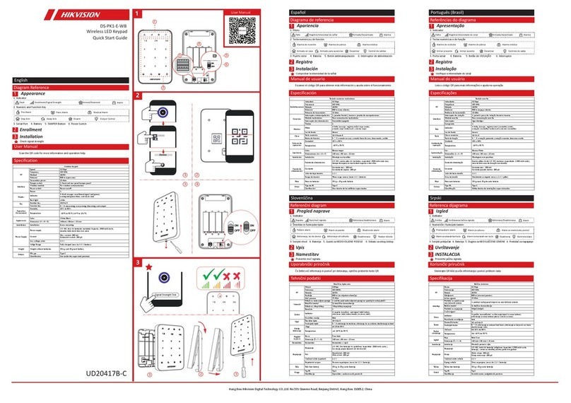
Enrollment
English
Diagram Reference
Specification
Components and Indicaon
1
3
Installaon4
5
Power On
2
Power on the security control panel.
Make the control panel enter the
enrollment mode. Press the tamper
switch (on the board) of the keypad. The
paron indicators flashes 4 mes when
the keypad is enrolled and ready for
work.
Note: The distance between the security
control panel and the keypad should be
less than 50 cm.
1. Loosen the set screws on boom of the keypad.
2. Remove the mounng plate.
3. Install four AA baeries according to the polarity mark.
Note: Do not reverse the polarity of the baery.
Check Signal Strength
Enter the signal checking mode by operang on the control panel.
Trigger the tamper alarm.
Power indicator flashes 3 mes - Strong Signal
Fault indicator flashes 3 mes - Weak Signal
Buzzer
1. Indicator
2. Tag Area
3. TAMPER Switch (on the board)
Power
IndicatorGreen
Blue
Orange
Red
Keypad Backlight White Keypad locked: flashes 2 times
Turn off if no operation for 5 s, turn on when touched
Normal Battery: Solid green for 2s (keypad waked up)
Low Battery:Flashing green flashes 3 times (keypad waked up)
Weak Signal Strength:Flashes 3 times
Strong Signal Strength:Flashes 3 times
Armed: Related LED flashes once, and light on 2 s while
the keypad is waked up
Disarmed/Alarm Cleared:Related LED flashes twice
Operation failed: Related LED flashes 3 times
Alarm: Related LED flashes 30s
Enrolled and Starts work: 4 LEDs flashes 4 times together
Patrol tag presented: Power and Fault LEDs flashes 2 times
Zone/ Fire Alarm Triggered:Flashes 30s
No Alarm or Alarm Restored:Off
Partition
Indicator
Fault
Indicator
Alarm
Indicator
Present Tag/Tap Key/Armed
Disarmed
Operation Failed
Keypad Tampered
Tag Enrolled
Zone Tampered
Fire Alarm
Beep Beep Beep
Beep Beep Beep Beep Beep
Beep
Beep
Long Beep (30 s)
Long Beep (30 s)
Beep Beep
Formang
Remove the baery. Hold the TAMPER buon (with slend rod) and power
the keypad on at the same me. Release the buon when any of the
power, alarm, or fault indicators starts flash. The four indicators flash 4
me aer the formang is completed.
Local Enrollment APP Enrollment
Operaon
Operation
All Partition
1. Enter the user password.
2. Tap the stay/away/disarm key.
Specified
Partition
1
. Tap the user password.
2
. Tap the √ key.
3
.
Enter the partition No.(1/2/3/4).
4
. Tap the stay/away/disarm key.
Partition
Keypad
Fire Alarm
Panic Alarm
Confirm
Tasks
1
.Enter the user password.
2
.Tap the stay/away/disarm key.
Stay/Away Arming
Disarming
Global Keypad
Hold the fire alarm key for 3 s.
Hold the disarming key for 3 s.
Tap the √ key.
1Away Arming
Other
Operaon
Tag Operaon 2Stay Arming 3Disarming
Delete Delete the latest key operation
The buzzer indicates the operation status
3. The buzzer indicates the
operation status
5. The buzzer indicates the
operation status
The buzzer indicates the operation status
1. Log in to the APP Store. Search for
“Hik-Connect” .Download and install the
client to your phone. Run the client.
2. Power on the security control panel.
3. Log in the client and tap the icon “+”
to add the control panel. Scan the QR
code or input the device serial No.
(serial No. is not supported by device
with 868 RF frequency). to add the
device( in the registraon mode).
4. Tap the “+” icon on the device page
to add the peripherals.
RF speed 10.0kbps/4.8kbps
RF frequency 433.6MHz/868.05MHz
RF method 2GFSK
Transmission distance 800m (open area)
Power 10dBm
Tamper-proof 1 tamper switch, front and rear tamper-proof
Wireless Module Communicates with control panel
Card reader Supports standard IC card
Buzzer 1
Serial port 1, reserved
Indicator 3status indicators:power (green), fault (red), and alarm (red)
4paron indicators:armed/disarmed (blue)
Backlight 1 group,white
Numeric key 10, 0 to 9
Funcon key 6, fire, away arming, stay arming, diarming, deleng, and OK
Electrical & Baery Power 4AA Baeries,3V DC,≥ 2 years standby
Operaon humidity 10%to 90%
Operaon temperature ﹣10℃to +55℃
Color White/Black
Installaon Wall mounng with screws
Dimension Diameter:132 mm (52"), Deep:23mm(9")
Weight 165 g (without baery)
Wireless Keypad
RF
Interface and
Component
Others
UD15019B
4. Faites tourner le corps du clavier dans le sens horaire pour fixer le corps sur la plaque.
5. Serrez la vis du bas pour fixer le clavier sur la plaque de montage et terminer l’installaon.
Inscripon
Français
Références du schéma
Spécificaon
Composants et indicaon
1
3
Installaon4
5
Mise sous tension
2
Il est nécessaire d’insérer la vis pour l’alarme de sabotage.
Inscripon locale
Allumez le panneau de commande de sécurité.
Accédez au mode inscripon sur le panneau de
commande. Appuyez sur le contact ansabotage
(intégré sur la carte) du clavier. Lorsque le clavier
est inscrit et prêt à fonconner, les voyants de
paron clignotent 4 fois.
Remarque : la distance entre le panneau de
commande de sécurité et le clavier doit être
inférieure à 50 cm.
1. Desserrez les vis de fixaon situées au bas du clavier.
2. Rerez la plaque de montage.
3. Installez 4 piles de type AA en respectant les marques de polarité.
Remarque : ne pas inverser la polarité des piles.
Vérifier la puissance du signal
Accédez au mode de mesure du signal à parr du panneau de commande. Déclenchez l’alarme de
sabotage.
Le voyant d’alimentaon clignote 3 fois : le signal est fort
Le voyant de panne clignote 3 fois : le signal est faible
1. Desserrez les vis de fixaon situées au bas du clavier.
2. Tournez dans le sens anhoraire pour rerer la plaque de montage.
3. Fixez la plaque de montage sur le mur à l’aide des 4 vis fournies.
Aversseur
1. Voyant
2. Zone de radioéquee
3. Contact ansabotage (intégré sur la carte)
Vert
Bleu
Orange
Rouge
Rétroéclairage du clavier Blanc Clavier bloqué : le voyant clignote 2 fois
Il s’éteint si aucune opéraon n’est effectuée pendant 5 s. Il s’allume au toucher
Alarme de zone/incendie déclenchée : le voyant clignote pendant 30 s
Aucune alarme ou fin d’alarme : le voyant est éteint
Formatage
Rerez la baerie. Appuyez sur et maintenez enfoncé le bouton SABOTAGE (avec une ge mince) et
meez sous tension le clavier en même temps. Relâchez le bouton dès que l’un des voyants
d’alimentaon, d’alarme ou de panne se met à clignoter. Une fois le formatage terminé, les 4 voyants
clignotent 4 fois.
RF
Opéraon
12 3
Inscripon dans l’applicaon
1. Connectez-vous au magasin d’applicaon APP
Store. Recherchez l’applicaon « Hik-Connect ».
Téléchargez et installez le client sur votre
téléphone. Exécutez le client.
2. Allumez le panneau de commande de sécurité.
3. Connectez-vous au client et appuyez sur l’icône
« + » pour ajouter le panneau de commande.
Scannez le code QR ou saisissez le numéro de
série de l’appareil (le numéro de série n’est pas
pris en charge par un appareil fonconnant à la
radiofréquence de 868 MHz) pour ajouter
l’appareil (en mode enregistrement).
4. Appuyez sur l’icône « + » dans la page de
l’appareil pour ajouter les périphériques.
Piles normales : le voyant est vert connu pendant 2 s (clavier réacvé)
Piles faibles : le voyant clignote 3 fois en vert (clavier réacvé)
Radioéquee de patrouille présentée : les voyants d’alimentaon et de panne
clignotent 2 fois
Puissance du signal forte : le voyant clignote 3 fois
Armé : le voyant correspondant clignote une seule fois et s’allume pendant 2 s tandis
que le clavier est réacvé.
Désarmée/alarme annulée : le voyant correspondant clignote 2 fois
Échec de l’opéraon : le voyant correspondant clignote 3 fois
Alarme : le voyant correspondant clignote pendant 30 s
Appareil inscrit et début de fonconnement : les 4 voyants clignotent simultanément
4 fois
Puissance du signal faible : le voyant clignote 3 fois
Radioéquee de patrouille présentée : les voyants d’alimentaon et de panne
clignotent 2 fois
Voyant
d’alimentaon
Indicateur
de paron
Voyant de
panne
Voyant
d’alarme
Ulisaon des
radioéquees
Armement en mode
absence
Armement en mode à
domicile Désarmement
Autre ulisaon
Opéraon Tâches
Armement en mode à
domicile/absence
Désarmement
Clavier global
Clavier de la
paron
Toutes les
parons
Paron
spécifiée
Alarme d’incendie
Alarme de panique
Confirmer
Supprimer
Appuyez sur la touche √.
Supprime la dernière opéraon de la touche.
Maintenez la touche d’alarme incendie enfoncée pendant 3 s.
L’aversseur indique l’état de l’opéraon.
Maintenez la touche de désarmement enfoncée pendant 3 s.
L’aversseur indique l’état de l’opéraon.
1. Saisissez le mot de passe de l’ulisateur.
2. Appuyez sur la touche mode à domicile/absence/désarmer.
1. Saisissez le mot de passe de l’ulisateur.
2. Appuyez sur la touche mode à
domicile/absence/désarmer.
3. L’aversseur indique l’état de l’opéraon.
1. Saisissez le mot de passe de l’ulisateur.
2. Appuyez sur la touche √.
3. Saisissez le numéro de paron (1/2/3/4).
4. Appuyez sur la touche mode à
domicile/absence/désarmer.
5. L’aversseur indique l’état de l’opéraon.
3 voyants d’état : alimentaon (vert), panne (orange) et alarme (rouge)
4 voyants de paron : armé/désarmé (bleu)
Présentaon d’une radioéquee/Appui sur une touche/Armé
Désarmé
Échec de l’opéraon
Sabotage du clavier
Radioéquee inscrite
Sabotage d’une zone
Alarme d’incendie
Bip
Bip Bip
Bip Bip Bip
Bip Bip Bip Bip Bip
Bip
Bip long (30 s)
Bip long (30 s)
Interface et composant
Caractérisques électriques et piles
Autres
Vitesse RF
Fréquence RF
Méthode RF
Distance de transmission
Puissance
Ansabotage
Module sans fil
Lecteur de radioéquee
Aversseur
Port série
10,0 kbit/s/4,8 kbit/s
433 MHz/868 MHz
2GFSK
800 m (espace dégagé)
10 dBm
1 contact ansabotage à l’avant et à l’arrière
Communicaon avec le panneau de commande
Prise en charge de carte à puce
1
1, réservé
Clavier sans fil
Voyant
Rétroéclairage
Touche numérique
Touche de foncon
Alimentaon
Humidité de fonconnement
Température de fonconnement
Couleur
Installaon
1 groupe
10 (de 0 à 9)
6 (incendie, armement en mode absence, armement en mode à domicile, désarmement,
suppression et OK)
4 piles de type AA, 3 V CC, autonomie en veille ≥ 3 ans
10 à 90 %
-10 à +55 °C
Blanc/Noir
Montage mural par vis
4. Gire o corpo do teclado no sendo horário para prendê-lo na placa.
5. Aperte o parafuso na parte inferior para fixar o teclado na placa de montagem e finalize a instalação.
Registro
Português
Referências do diagrama
Especificação
Componentes e indicação
1
3
Instalação4
5
Avação
2
É necessário inserir o parafuso para o alarme de violação.
Registro local
Ligue o painel de controle de segurança. Faça com
que o painel de controle entre em modo de
registro. Pressione a chave de violação (na placa) do
teclado. Os indicadores de parção piscarão 4 vezes
quando o teclado esver registrado e pronto para
operação.
Observação: a distância entre o painel de controle
de segurança e o teclado deve ser menor do que
50 cm.
1. Solte os parafusos de ajuste na parte inferior do teclado.
2. Rere a placa de montagem.
3. Instale quatro pilhas AA de acordo com a marcação de polaridade.
Observação: não inverta a polaridade das pilhas.
Verificar a intensidade do sinal
Entre no modo de verificação de sinal operando pelo painel de controle. Acione o alarme de violação.
Indicador de energia pisca 3 vezes - sinal forte
Indicador de falha pisca 3 vezes - sinal fraco
1. Solte os parafusos de ajuste na parte inferior do teclado.
2. Gire no sendo an-horário para rerar a placa de montagem.
3. Fixe a placa de montagem na parede com os quatro parafusos fornecidos.
Campainha
1. Indicador
2. Área da tag
3. Chave de VIOLAÇÃO (na placa)
Verde
Azul
Laranja
Vermelho
Luz de fundo do teclado Branco Teclado bloqueado: pisca duas vezes
Desliga se não houver operação por 5 s; liga quando houver algum toque
Alarme de zona/incêndio avado: Pisca por 30 s
Nenhum alarme ou alarme redefinido: Desligado
Formatação
Remova a bateria. Pressione o botão VIOLAÇÃO (com uma haste fina) e ligue o teclado ao mesmo tempo.
Solte o botão quando o indicador de energia, de alarme ou de falha começar a piscar. Os quatro
indicadores piscarão 4 vezes quando a formatação for finalizada.
RF
Operação
12 3
Registro no app
1. Acesse a loja de apps. Procure por
“Hik-Connect”. Baixe e instale o cliente em seu
telefone. Execute o cliente.
2. Ligue o painel de controle de segurança.
3. Acesse o cliente e toque no ícone “+” para
adicionar o painel de controle. Leia o código
QR ou insira o número de série do disposivo
(o número de série não é suportado por
disposivos com frequência de RF 868).
4. Toque no ícone “+” na página do disposivo
para adicionar os periféricos.
Pilhas normais: aceso em verde por 2 s (teclado avo)
Pilhas fracas: pisca em verde 3 vezes (teclado avo)
Tag de patrulha apresentada: LEDs de energia e de falha piscam 2 vezes
Intensidade de sinal alta: pisca 3 vezes
Armado: LED correspondente pisca uma vez e acende por 2 s enquanto o teclado é
avado.
Desarmado/Alarme eliminado: LED correspondente pisca duas vezes
Falha na operação: LED correspondente pisca 3 vezes
Alarme: LED correspondente pisca por 30 s
Registrado e ao começar a funcionar: os 4 LEDs piscam juntos 4 vezes
Intensidade de sinal baixa: pisca 3 vezes
Tag de patrulha apresentada: LEDs de energia e de falha piscam 2 vezes
Indicador
de energia
Indicador
de parção
Indicador
de falha
Indicador
de alarme
Operação de tag Armação remota Armação de
permanência Desarme
Outra
operação
Operação Tarefas
Armação e desarme
local/remoto
Teclado global
Teclado da
parção
Todas as
parções
Parção
especificada
Alarme de incêndio
Alarme de pânico
Confirmar
Excluir
Toque na tecla √.
Exclua a úlma operação da tecla.
Pressione a tecla alarme de incêndio por 3 s.
A campainha indica o status de operação.
Pressione a tecla de desarme por 3 s.
A campainha indica o status de operação.
1. Insira a senha do usuário.
2. Toque na tecla local/remoto/desarme.
1. Insira a senha do usuário.
2. Toque na tecla local/remoto/desarme.
3. A campainha indica o status de
operação.
1. Digite a senha do usuário.
2. Toque na tecla √.
3. Insira o número da parção (1/2/3/4).
4. Toque na tecla local/remoto/desarme.
5. A campainha indica o status de operação.
3 indicadores de status: energia (verde), falha (laranja) e alarme (vermelho)
4 indicadores de parção: armado/desarmado (azul)
Apresentar tag/Tocar na tecla/Armado
Desarmado
Falha na operação
Teclado violado
Tag registrada
Zona violada
Alarme de incêndio
Um bipe
Dois bipes
Três bipes
Cinco bipes
Um bipe
Bipe longo (30 s)
Bipe longo (30 s)
Interface e componente
Componentes elétricos e pilhas
Outros
Velocidade de RF
Frequência de RF
Método de RF
Distância de transmissão
Potência
Anviolação
Módulo sem fio
Leitor de tag
Campainha
Porta serial
10,0 kbps/4,8 kbps
433 MHz/868 MHz
2GFSK
800 m (espaço aberto)
10 dBm
1 chave de violação, frente e traseira invioláveis
Comunica-se com o painel de controle
Suporta cartão IC padrão
1
1, reservado
Teclado sem fio
Indicador
Luz de fundo
Tecla numérica
Tecla de função
Alimentação
Umidade de operação
Temperatura de operação
Cor
Instalação
1 grupo
10, 0 a 9
6, incêndio, armação remota, armação local, desarme, exclusão e OK
4 pilhas AA, 3 VCC, ≥ 3 anos em stand-by
10% a 90%
-10°C a +55°C
Branco/Preto
Montagem na parede com parafusos
4. Ruotare il corpo della tasera in senso orario per stringerlo sulla piastra di montaggio.
5. Stringere la vite alla base per fissare la tasera sulla piastra di montaggio e completare
l’installazione.
Registrazione
Italiano
Riferimen agli schemi
Specifiche
Componen e indicazioni
1
3
Installazione4
5
Accensione
2
È necessario inserire la vite per avare l'allarme an-manomissione.
Registrazione locale
Accendere il pannello di controllo di sicurezza.
Accedere alla modalità di registrazione dal pannello
di controllo. Premere l'interruore
an-manomissione (sul pannello di controllo) della
tasera. Gli indicatori di parzione lampeggiano
4 volte quando la tasera viene registrata ed è
pronta per essere ulizzata.
Nota: la distanza tra il pannello di controllo di
sicurezza e la tasera deve essere inferiore a 50 cm.
1. Allentare le vi alla base della tasera.
2. Rimuovere la piastra di montaggio.
3. Installare quaro baerie AA, rispeando la polarità indicata.
Nota: Non inverre la polarità delle baerie.
Controllo intensità del segnale
Entrare in modalità di controllo del segnale agendo sul pannello di controllo. Avazione allarme
an-manomissione.
L'indicatore di alimentazione lampeggia 3 volte - Segnale forte
L'indicatore di errore lampeggia 3 volte - Segnale debole
1. Allentare le vi alla base della tasera.
2. Ruotare la piastra di montaggio in senso anorario per rimuoverla.
3. Fissare la piastra di montaggio alla parete ulizzando le quaro vi fornite in dotazione.
Avvisatore acusco
1. Indicatore LED
2. Area tag
3. Interruore an-manomissione (sul pannello di controllo)
Verde
Blu
Arancione
Rosso
Retroilluminazione
tasera Bianco Tasera bloccata: lampeggia 2 volte
Si spegne in caso di inulizzo per 5 secondi e si accende toccandolo
Allarme zona/incendio avato: Lampeggia per 30 secondi
Nessun allarme o allarme riprisnato: Spento
Formaazione
Rimuovere la baeria. Tenere premuto il pulsante ANTI-MANOMISSIONE (con l'apposita ascella) e allo
stesso tempo accendere la tasera. Rilasciare il pulsante quando gli indicatori di alimentazione, di allarme
o di errore iniziano a lampeggiare. I quaro indicatori lampeggiano 4 volte una volta completata la
formaazione.
RF
Funzionamento
12 3
Registrazione dell'app
1. Accedere all'App Store. Cercare "Hik-Connect".
Scaricare e installare l'applicazione client sul
telefono. Lanciare l'applicazione client.
2. Accendere il pannello di controllo di sicurezza.
3. Accedere all'applicazione client e toccare l'icona
"+" per aggiungerla al pannello di controllo.
Eseguire la scansione del codice QR o immeere
il numero di serie del disposivo (il numero di
serie non è supportato dai disposivi con
frequenza RF 868) per aggiungere il disposivo
(in modalità di registrazione).
4. Toccare l'icona "+" sulla pagina del disposivo
per aggiungere le periferiche.
Baeria normale: Verde acceso per 2 secondi (la tasera si riava)
Baeria scarica: Verde lampeggiante per 3 volte (la tasera si riava)
Tag paugliamento presente: I LED di alimentazione e di errore lampeggiano 2 volte
Potenza segnale forte: Lampeggia 3 volte
Inserito: Il LED corrispondente lampeggia una volta e rimane acceso 2 secondi
quando la tasera si riava.
Allarme disinserito/cancellato: il LED corrispondente lampeggia due volte
Operazione non riuscita: Il LED corrispondente lampeggia 3 volte
Allarme: Il LED corrispondente lampeggia 30 secondi
Avità registrata: I 4 LED lampeggiano 4 volte contemporaneamente
Potenza segnale debole: Lampeggia 3 volte
Tag paugliamento presente: I LED di alimentazione e di errore lampeggiano 2 volte
Indicatore di
alimentazione
Indicatore
di parzione
Indicatore
di errore
Indicatore
di allarme
Funzione dei tag Inserimento in modalità
assenza
Inserimento modalità
presenza Disinserimento
Altre operazioni
Funzionamento Avità
Inserimento/Disinserimento
presenza/assenza
Tasera globale
Tasera parzione
Tue le parzioni
Parzione
specificata
Allarme incendio
Allarme panico
Conferma
Cancella
Toccare il tasto √.
Cancellare l'ulma operazione eseguita con il tasto.
Tenere premuto il tasto di allarme incendio per 3 secondi.
L'avvisatore acusco indica lo stato di funzionamento.
Tenere premuto il tasto di disinserimento per 3 secondi.
L'avvisatore acusco indica lo stato di funzionamento.
1. Immeere la password utente.
2. Toccare il tasto di disinserimento presenza/assenza.
1. Immeere la password utente.
2. Toccare il tasto di disinserimento presenza/assenza.
3. L'avvisatore acusco indica lo stato di
funzionamento.
1. Immeere la password utente.
2. Toccare il tasto √.
3. Immeere il n. di parzione (1/2/3/4).
4. Toccare il tasto di disinserimento
presenza/assenza.
5. L'avvisatore acusco indica lo stato di
funzionamento.
3 indicatori di stato: alimentazione (verde), errore (arancione) e allarme (rosso)
4 indicatori di parzione: inserito/disinserito (blu)
Presenza tag/Tocca tasto/Inserito
Disinserito
Operazione non riuscita
Tasera manomessa
Tag registrato
Zona manomessa
Allarme incendio
Un segnale acusco
Due segnali acusci
Tre segnali acusci
Cinque segnali acusci
Un segnale acusco
Un segnale acusco prolungato (30 secondi)
Interfaccia e componen
Elericità e baeria
Altro
Velocità RF
Frequenza RF
Metodo RF
Distanza di trasmissione
Alimentazione
An-manomissione
Modulo wireless
Leore di tag
Avvisatore acusco
Porta seriale
10,0 kbps/4,8 kbps
433 MHz/868 MHz
2 GFSK
800 m (spazi aper)
10 dBm
1 interruore an-manomissione anteriore e posteriore
Comunica con il pannello di controllo
Supporta una scheda IC standard
1
1, riservato
Tasera wireless
Indicatore LED
Retroilluminazione
Tasto numerico
Tasto funzione
Alimentazione
Umidità operava
Temperatura di esercizio
Colore
Installazione
1 gruppo
10, da 0 a 9
6, incendio, inserimento assenza, inserimento presenza, disinserimento, eliminazione e OK
4 baerie AA, 3 V CC, tempo di stand-by ≥ 3 anni
Da 10% a 90%
Da -10 °C a +55 °C
Bianco/Nero
Montaggio a parete con vi
4. Gire la carcasa del teclado numérico en sendo horario para asegurar la carcasa al disco.
5. Apriete el tornillo ubicado en la parte inferior para fijar el teclado numérico al disco de montaje y
completar la instalación.
Registro
Español
Diagrama de referencia
Especificaciones
Componentes e indicación
1
3
Instalación4
5
Encendido
2
Se requiere introducir el tornillo para la alarma de manipulación.
Registro local
Encienda el panel de control de seguridad. En el
panel de control, acceda al modo de registro. Pulse
el interruptor de manipulación (en el tablero) del
teclado numérico. Una vez registrado y operavo el
teclado numérico, los indicadores de parción
parpadean 4 veces.
Nota: La distancia entre el panel de control de
seguridad y el teclado numérico debe ser inferior
a 50 cm.
1. Afloje los tornillos de fijación ubicados en la parte inferior del teclado numérico.
2. Extraiga el disco de montaje.
3. Inserte cuatro pilas AA respetando las marcas de polaridad.
Nota: No invierta la polaridad de las pilas.
Comprobar la intensidad de la señal
Acceda al modo de comprobación de la señal ulizando el panel de control. Dispare la alarma de
manipulación.
El indicador de alimentación parpadea 3 veces: señal fuerte
El indicador de fallo parpadea 3 veces: señal débil
1. Afloje los tornillos de fijación ubicados en la parte inferior del teclado numérico.
2. Gire en sendo anhorario para extraer el disco de montaje.
3. Fije el disco de montaje a la pared con los cuatro tornillos suministrados.
Timbre
1. Indicador
2. Área para la equeta
3. Interruptor de MANIPULACIÓN (en el tablero)
Verde
Azul
Naranja
Rojo
Luz de fondo del
teclado numérico Blanco Teclado numérico bloqueado: parpadea 2 veces
Se apaga si no se realiza ninguna operación durante 5 s, se enciende al tocarlo
Alarma de zona/incendio disparada: Parpadea 30 s
Ninguna alarma o alarma restaurada: Apagado
Formateo
Rere las pilas. Mantenga pulsado el botón MANIPULACIÓN (con la varilla) y encienda el teclado
numérico al mismo empo. Suelte el botón cuando cualquiera de los indicadores de alimentación, alarma
o fallo comience a parpadear. Los cuatro indicadores parpadean 4 veces una vez completado el formateo.
Radiofrecuencia
Funcionamiento
12 3
Registro de la aplicación
1. Acceda a APP Store. Busque «Hik-Connect».
Descargue e instale la aplicación en su teléfono.
Ejecute la aplicación.
2. Encienda el panel de control de seguridad.
3. Inicie sesión en la aplicación y pulse el icono «+»
para agregar el panel de control. Estando en el
modo de registro, escanee el código QR o
introduzca el n.º de serie del disposivo para
agregar el disposivo (la introducción del n.º de
serie no es compable con los disposivos con
frecuencia de radiofrecuencia de 868).
4. Pulse el icono «+» en la página del disposivo
para agregar los periféricos.
Carga normal de las pilas: Verde fijo durante 2 s (teclado numérico acvado)
Carga baja de las pilas: Parpadea en verde 3 veces (teclado numérico acvado)
Equeta de patrulla presentada: Los ledes de fallo y alimentación parpadean
2 veces
Intensidad de señal fuerte: Parpadea 3 veces
Armado: El led relacionado parpadea una vez, iluminándose durante 2 s mientras que
el teclado numérico esté acvado.
Alarma desarmada/borrada: el led relacionado parpadea 2 veces
Error en la operación: El led relacionado parpadea 3 veces
Alarma: El led relacionado parpadea 30 s
Registrado y empieza a funcionar: Cuatro ledes parpadean 4 veces al mismo
empo
Intensidad de señal débil: Parpadea 3 veces
Equeta de patrulla presentada: Los ledes de fallo y alimentación parpadean 2 veces
Indicador de
alimentación
Indicador
de parción
Indicador
de fallo
Indicador
de alarma
Operaciones con
equeta Armado de ausencia Permanecer armado Desarmado
Otras
operaciones
Funcionamiento Tareas
Armado/desarmado de
presencia/ausencia
Teclado numérico
global
Teclado numérico
de parción
Todas las
parciones
Parción
especificada
Alarma de incendio
Alarma de pánico
Confirmar
Eliminar
Pulse la tecla √.
Elimina la úlma operación de la tecla.
Mantenga pulsada la tecla de la alarma de incendio durante 3 s.
El mbre indica el estado de funcionamiento.
Mantenga pulsada la tecla de desarmado durante 3 s.
El mbre indica el estado de funcionamiento.
1. Introduzca la contraseña de usuario.
2. Pulse la tecla de desarmado de presencia/ausencia.
1. Introduzca la contraseña de usuario.
2. Pulse la tecla de desarmado de
presencia/ausencia.
3. El mbre indica el estado de funcionamiento.
1. Introduzca la contraseña de usuario.
2. Pulse la tecla √.
3. Introduzca el n.º de parción (1, 2, 3 o 4).
4. Pulse la tecla de desarmado de
presencia/ausencia.
5. El mbre indica el estado de funcionamiento.
3 indicadores de estado: alimentación (verde), fallo (naranja) y alarma (rojo)
4 indicadores de parción: armado/desarmado (azul)
Presentar equeta/pulsar tecla/armado
Desarmado
Error en la operación
Teclado numérico manipulado
Equeta registrada
Zona manipulada
Alarma de incendio
Pido
Pido pido
Pido pido pido
Pido pido pido pido pido
Pido
Pido prolongado (30 s)
Conexión y componentes
Electricidad y pilas
Otros
Velocidad de radiofrecuencia
Frecuencia de radiofrecuencia
Método de radiofrecuencia
Distancia de transmisión
Alimentación
Anmanipulación
Módulo inalámbrico
Lector de equetas
Timbre
Puerto serie
10 kbps/4,8 kbps
433 MHz/868 MHz
2-GFSK
800 m (área abierta)
10 dBm
1 interruptor de manipulación, anmanipulación frontal y posterior
Se comunica con el panel de control
Compable con tarjetas de circuito integrado comunes
1
1, reservado
Teclado numérico inalámbrico
Indicador
Luz de fondo
Tecla numérica
Tecla de función
Alimentación
Humedad de funcionamiento
Temperatura de funcionamiento
Color
Instalación
1 grupo
10: de 0 a 9
6: incendio, armado de ausencia, armado de presencia, desarmado, eliminar y aceptar
4 pilas AA, 3 VCC, ≥ 3 años en modo de espera
10 % a 90 %
De -10 °C a +55 °C
Blanco/negro
Montaje mural con tornillos
4. Поверните корпус клавиатуры по часовой стрелке, чтобы прикрепить его к монтажной пластине.
5. Затяните винт в нижней части, чтобы зафиксировать клавиатуру на монтажной пластине и
завершить установку.
Регистрация
Русский
Пояснения к схемам
Технические данные
Компоненты и индикаторы
1
3
Установка4
5
Включение устройства
2
Требуется закрутить винт для сигнализации взлома.
Локальная регистрация
Включите панель управления системой
безопасности. Включите режим регистрации на
панели управления системой безопасности.
Нажмите датчик взлома на печатной плате
клавиатуры. Когда клавиатура зарегистрируется
и будет готова к работе, индикаторы разделов
мигнут 4 раза.
Примечание: Расстояние между панелью
управления системой безопасности и
клавиатурой должно быть менее 50 см.
1. Ослабьте фиксирующие винты на основании клавиатуры.
2. Снимите монтажную пластину.
3. Установите четыре батареи типа ААА, соблюдая полярность.
Примечание: Не перепутайте полярность батарей.
Проверка уровня сигнала
Включите режим проверки уровня сигнала на панели управления. Запустите тревогу взлома.
Индикатор питания мигает 3 раза – мощный сигнал
Индикатор отказа мигает 3 раза – слабый сигнал
1. Ослабьте фиксирующие винты на основании клавиатуры.
2. Поверните монтажную пластину против часовой стрелки, чтобы снять ее.
3. Прикрепите монтажную пластину к стене с помощью четырех прилагаемых винтов.
Зуммер
1. Индикатор
2. Область действия брелока
3. Датчик ВЗЛОМА (на плате)
Зеленый
Синий
Оранжевый
Красный
Подсветка клавиатуры Белый Клавиатура заблокирована: мигает 2 раза
Выключается при отсутствии активности в течение 5 сек., включается при прикосновении
Срабатывание пожарной сигнализации/сигнализации зоны: мигает 30 сек.
Нет сигналов тревоги или они сброшены: выкл.
Форматирование
Извлеките батареи. Удерживая кнопку ВЗЛОМА (с помощью тонкой шпильки), подайте питание на
клавиатуру. Отпустите кнопку, когда начнет мигать любой из индикаторов (питания, тревоги или
отказа). Когда форматирование будет выполнено, четыре индикатора мигнут 4 раза.
Радиоканал
Операция
12 3
Регистрация в приложении
1. Войдите в APP Store. Найдите клиентское
приложение «Hik-Connect». Скачайте его и
установите на телефон. Запустите клиентское
приложение.
2. Включите панель управления системой
безопасности.
3. Войдите в клиентское приложение и нажмите
значок «+», чтобы добавить панель
управления. Чтобы добавить устройство
(в режиме регистрации), отсканируйте QR-код
или введите серийный номер устройства (ввод
серийного номера не поддерживается для
устройств с радиочастотой 868 МГц).
4. Для добавления периферийных устройств
нажмите значок «+» на странице устройства.
Нормальное состояние батарей: зеленый индикатор непрерывно светится 2 сек. (клавиатура
инициализирована)
Батареи разряжены: зеленый индикатор мигает 3 раза (клавиатура инициализирована)
Патрульный брелок поднесен: светодиоды питания и отказа мигают 2 раза
Мощный сигнал: индикатор мигает 3 раза
Постановка на охрану: соответствующий светодиод мигнет один раз, а затем будет светиться
постоянно 2 сек., пока выполняется инициализация клавиатуры.
Снято с охраны/тревога сброшена: соответствующий светодиод мигнет два раза
Сбой операции: соответствующий светодиод мигнет 3 раза
Тревога: соответствующий светодиод мигает в течение 30 сек.
Устройство зарегистрировано и начало работать: все 4 светодиода мигнут 4 раза
Слабый сигнал: индикатор мигает 3 раза
Патрульный брелок поднесен: светодиоды питания и отказа мигают 2 раза
Индикатор
питания
Индикатор
разделов
Индикатор
сбоя
Индикатор
тревоги
Операции с
брелоком
Полная охрана Частичная охрана Снятие с охраны
Другие
операции
Операция Задачи
Постановка на полную/
частичную охрану и снятие с
полной/частичной охраны
Общая клавиатура
Клавиатура
раздела
Все разделы
Заданный
раздел
Пожарная тревога
Экстренная тревога
Подтвердить
Удалить
Нажмите кнопку √.
Удаление последней операции, связанной с нажатием кнопки.
Нажмите кнопку пожарной тревоги и удерживайте ее 3 сек.
Зуммер подтверждает выполнение операции.
Нажмите кнопку снятия с охраны и удерживайте ее 3 сек.
Зуммер подтверждает выполнение операции.
1. Введите пароль пользователя.
2. Нажмите кнопку снятия с полной/частичной охраны.
1. Введите пароль пользователя.
2. Нажмите кнопку снятия с полной/частичной
охраны.
3. Зуммер подтверждает выполнение операции.
1. Введите пароль пользователя.
2. Нажмите кнопку √.
3. Введите номер раздела (1/2/3/4).
4. Нажмите кнопку снятия с полной/частичной
охраны.
5. Зуммер подтверждает выполнение операции.
3 индикатора состояния: питание (зеленый), сбой (оранжевый) и тревога
(красный)
4 индикатора разделов: постановка на охрану/снятие с охраны (синие)
Поднесение брелока/нажатие кнопки/постановка на охрану
Снятие с охраны
Сбой операции
Клавиатура взломана
Брелок зарегистрирован
Взлом зоны
Пожарная тревога
1 сигнал
2 сигнала
3 сигнала
5 сигналов
1 сигнал
Продолжительный звуковой сигнал (30 сек.)
Интерфейс и компоненты
Электропитание и батареи
Прочее
Скорость передачи данных по радиоканалу
Радиочастота
Метод радиопередачи
Дальность передачи
Питание
Защита от взлома
Беспроводной модуль
Считыватель брелоков
Зуммер
Последовательный порт
10,0/4,8 кбит/с
433/868 МГц
2GFSK
800 м (на открытом пространстве)
10 дБм
1 датчик взлома, защита от вскрытия спереди и сзади
Связь с панелью управления
Поддержка стандартных IC-карт
1
1 (резервный)
Беспроводная клавиатура
Индикатор
Подсветка
Цифровая кнопка
Функциональная кнопка
Питание
Влажность при эксплуатации
Рабочая температура
Цвет
Установка
1 группа
10: от 0 до 9
6: пожарная охрана, полная охрана, частичная охрана, снятие с охраны, удаление и OK
4 батареи типа АА, 3 В пост. тока, не менее 3 лет в режиме ожидания
10–90%
от -10°C до +55°C
Белый/черный
Настенный монтаж с помощью винтов
4. Drehen Sie das Tastenfeld-Gehäuse im Uhrzeigersinn, um das Gehäuse an der Plae zu befesgen.
5. Ziehen Sie die Schraube an der Unterseite an, um das Tastenfeld an der Montageplae zu befesgen
und die Montage abzuschließen.
Anmeldung
Deutsch
Verweis auf Schaubild
Technische Daten
Bestandteile und Anzeige
1
3
Montage4
5
Einschalten
2
Die Schraube für den Sabotagealarm muss eingesetzt werden.
Lokale Anmeldung
Schalten Sie die Alarmzentrale ein. Rufen Sie den
Registriermodus am Bedienfeld auf. Drücken Sie
den Sabotageschalter (auf der Plane) des
Tastenfeldes. Die Paronsanzeigen blinken
viermal, wenn das Tastenfeld angemeldet und
betriebsbereit ist.
Hinweis: Der Abstand zwischen Alarmzentrale und
dem Tastenfeld sollte unter 50 cm liegen.
1. Lösen Sie die Feststellschrauben unten am Tastenfeld.
2. Enernen Sie die Befesgungsplae.
3. Legen Sie vier AA-Baerien gemäß den Polaritätsmarkierungen ein.
Hinweis: Verpolen Sie die Baerien nicht.
Signalstärke überprüfen
Rufen Sie den Signalprüfmodus am Bedienfeld auf. Lösen Sie den Sabotagealarm aus.
Betriebsanzeige blinkt dreimal – starkes Signal
Fehleranzeige blinkt dreimal – schwaches Signal
1. Lösen Sie die Feststellschrauben unten am Tastenfeld.
2. Drehen Sie gegen den Uhrzeigersinn, um die Befesgungsplae zu enernen.
3. Befesgen Sie die Befesgungsplae mit vier beiliegenden Schrauben an der Wand.
Summer
1. Statusleuchte
2. Tag-Bereich
3. SABOTAGE-Schalter (auf der Plane)
Grün
Blau
Orange
Rot
Hintergrundbeleuchtung
des Tastenfelds Weiß Tastenfeld gesperrt: blinkt zweimal
Schaltet aus, wenn 5 s lang nicht bedient, schaltet ein bei Berührung
Zonen- / Feueralarm ausgelöst: Blinkt 30 s lang
Kein Alarm oder Alarm zurückgesetzt: Aus
Formaeren
Enernen Sie die Baerie. Halten Sie die SABOTAGE-Taste gedrückt (mit einem dünnen Stäbchen) und
schalten Sie gleichzeig das Tastenfeld ein. Lassen Sie die Taste los, wenn Betriebs-, Alarm- oder
Fehleranzeige zu blinken beginnt. Die vier Anzeigen blinken nach Abschluss der Formaerung viermal.
Funk
Betriebsart
12 3
App-Registrierung
1. Melden Sie sich beim App Store an. Suchen Sie
nach „Hik-Connect“. Laden Sie den Client herunter
und installieren Sie ihn auf Ihrem Smartphone.
Führen Sie den Client aus.
2. Schalten Sie die Alarmzentrale ein.
3. Melden Sie sich beim Client an und ppen Sie auf
das Symbol „+“, um das Bedienfeld hinzuzufügen.
Scannen Sie den QR-Code oder geben Sie die
Seriennummer des Geräts ein (Seriennummer
wird vom Gerät mit Funkfrequenz 868 MHz
nicht unterstützt), um das Gerät hinzuzufügen
(im Registrierungsmodus).
4. Tippen Sie auf das Symbol „+“ auf der Geräteseite,
um die Peripheriegeräte hinzuzufügen.
Baerie normal: Dauerha grün für 2 s (Tastenfeld aufgeweckt)
Baerie schwach: Blinkt dreimal grün (Tastenfeld aufgeweckt)
Patrouillen-Tag vorgezeigt: Die Betriebs- und Fehler-LEDs blinken zweimal
Signal stark: Blinkt dreimal
Scharfgeschaltet: Zugehörige LED blinkt einmal und leuchtet 2 s lang, während das Tastenfeld
aufgeweckt wird.
Unscharf / Alarm gelöscht: Zugehörige LED blinkt zweimal
Vorgang fehlgeschlagen: Zugehörige LED blinkt dreimal
Alarm: Zugehörige LED blinkt 30 s lang
Angemeldet und startet Betrieb: 4 LEDs blinken viermal zusammen
Signal schwach: Blinkt dreimal
Patrouillen-Tag vorgezeigt: Die Betriebs- und Fehler-LEDs blinken zweimal
Betriebsanzeige
Paronsanzeige
Fehleranzeige
Alarmanzeige
Tag-Betrieb Abwesend scharfschalten Anwesend
scharfschalten Unscharfschalten
Weitere
Betriebsarten
Betriebsart Aufgaben
(Un-)Scharfschaltung
anwesend / abwesend
Allgemeines
Tastenfeld
Paronstastenfeld
Alle Paronen
Angegebene
Paron
Feueralarm
Noallalarm
Bestägen
Löschen
Drücken Sie die √-Taste.
Letzte Tasteneingabe löschen.
Feueralarmtaste 3 s lang gedrückt halten.
Der Summer gibt den Betriebszustand an.
Unscharfschalte-Taste 3 s lang gedrückt halten.
Der Summer gibt den Betriebszustand an.
1. Geben Sie das Benutzerpasswort ein.
2. Tippen Sie auf die Taste für anwesend / abwesend / unscharfschalten.
1. Geben Sie das Benutzerpasswort ein.
2. Tippen Sie auf die Taste für anwesend /
abwesend / unscharfschalten.
3. Der Summer gibt den Betriebszustand an.
1. Geben Sie das Benutzerpasswort ein.
2. Drücken Sie die √-Taste.
3. Geben Sie die Paronsnummer (1 / 2 / 3 / 4)
ein.
4. Tippen Sie auf die Taste für anwesend /
abwesend / unscharfschalten.
5. Der Summer gibt den Betriebszustand an.
3 Statusanzeigen: Strom (grün), Fehler (orange) und Alarm (rot)
4 Paronsanzeigen: Scharf / unscharf (blau)
Tag vorzeigen / Taste ppen / scharfgeschaltet
Unscharfgeschaltet
Vorgang fehlgeschlagen
Tastenfeld saboert
Tag angemeldet
Zone saboert
Feueralarm
Piep
Piep piep
Piep piep piep
Piep piep piep piep piep
Piep
Langer Piepton (30 s)
Schnistellen und Bestandteile
Elektrische Spezifikaonen und Baerie
Sonsges
Funkgeschwindigkeit
Funkfrequenz
Funkmethode
Übertragungsreichweite
Leistung
Sabotagesicherheit
Funkmodul
Tag-Leser
Summer
Serielle Schnistelle
10,0 kbps / 4,8 kbps
433 MHz / 868 MHz
2GFSK
800 m (offenes Gelände)
10 dBm
1 Sabotageschalter, vorne und hinten sabotagesicher
Kommuniziert mit Bedienfeld
Unterstützt Standard-Chipkarte
1
1, belegt
Kabelloses Tastenfeld
Statusleuchte
Hintergrundbeleuchtung
Zifferntaste
Funkonstaste
Spannungsversorgung
Betriebsfeuchgkeit
Betriebstemperatur
Farbe
Montage
1 Gruppe
10, 0 bis 9
6, Feuer, abwesend scharfschalten, anwesend scharfschalten, unscharfschalten, löschen und OK
4 AA-Baerien, 3 V DC, ≥ 3 Jahre Standby
10 % bis 90 %
-10 °C bis +55 °C
Weiß / Schwarz
Wandmontage mit Schrauben
4. Obróć korpus panelu sterowania zgodnie z kierunkiem ruchu wskazówek zegara, aby przymocować
go do płyty.
5. Dokręć wkręt na podstawie, aby przymocować panel sterowania na płycie montażowej i ukończyć
instalację.
Rejestracja
Polski
Opis diagramu
Specyfikacje
Składniki i wskaźniki
1
3
Instalacja4
5
Włączanie zasilania
2
Wymagane jest użycie wkrętu zabezpieczenia antysabotażowego.
Rejestracja lokalna
Włącz zasilanie centrali alarmowej. Przełącz
centralę alarmową do trybu rejestracji. Naciśnij
przycisk zabezpieczenia antysabotażowego (na
płycie) centrali alarmowej. Wskaźniki partycji
zamigają 4 razy, gdy panel sterowania zostanie
zarejestrowany i uruchomiony.
Uwaga: odległość centrali alarmowej od panelu
sterowania powinna być mniejsza niż 50 cm.
1. Poluzuj śruby na podstawie panelu sterowania.
2. Usuń płytę montażową.
3. Zainstaluj cztery baterie AA zgodnie z oznaczeniem biegunów.
Uwaga: nie wolno odwracać biegunowości baterii.
Sprawdzanie siły sygnału
Przełącz do trybu sprawdzania sygnału, korzystając z panelu sterowania. Wyzwól alarm sabotażowy.
Wskaźnik zasilania zamiga 3 razy, jeżeli sygnał jest silny
Wskaźnik usterki zamiga 3 razy, jeżeli sygnał jest słaby
1. Poluzuj śruby na podstawie panelu sterowania.
2. Obróć płytę montażową przeciwnie do kierunku ruchu wskazówek zegara, aby ją odłączyć.
3. Przymocuj płytę montażową na ścianie czterema dostarczonymi wkrętami.
Brzęczyk
1. Wskaźnik
2. Obszar tagów
3. Przełącznik zabezpieczenia ANTYSABOTAŻOWEGO (na płycie)
Zielony
Niebieski
Pomarańczowy
Czerwony
Podświetlenie panelu
sterowania Biały Panel sterowania zablokowany: miga 2 razy
Wyłączony, jeżeli żadne operacje nie są wykonywane przez 5 s. Włączony po dotknięciu
Alarm strefowy/pożarowy: miga przez 30 s
Brak alarmu lub zresetowanie alarmu: wyłączony
Formatowanie
Wyjmij baterię. Naciśnij i przytrzymaj przycisk zabezpieczenia antysabotażowego (przedmiotem z cienkim
zakończeniem) i równocześnie włącz zasilanie panelu sterowania. Zwolnij przycisk, gdy dowolny wskaźnik
(zasilania, alarmu lub usterki) zacznie migać. Cztery wskaźniki zamigają 4 razy po ukończeniu formatowania.
Moduł radiowy
Operacja
12 3
Rejestracja w aplikacji
1. Zaloguj się do witryny internetowej APP Store.
Wyszukaj aplikację Hik-Connect. Pobierz
aplikację kliencką i zainstaluj ją na telefonie.
Uruchom aplikację kliencką.
2. Włącz zasilanie centrali alarmowej.
3. Zaloguj się do aplikacji klienckiej i naciśnij ikonę
„+”, aby dodać centralę alarmową. Zeskanuj kod
QR lub wprowadź numer seryjny urządzenia (nr
seryjny nie jest obsługiwany przez urządzenie
korzystające z częstotliwości radiowej 868 MHz),
aby dodać urządzenie (w trybie rejestracji).
4. Naciśnij ikonę „+” na stronie urządzenia, aby
dodać wyposażenie zewnętrzne.
Normalny stan baterii: włączony (zielony) przez 2 s (panel sterowania
uaktywniony)
Niskie napięcie baterii: miga (zielony) 3 razy (panel sterowania uaktywniony)
Zbliżenie tagu patrolowego: wskaźniki zasilania i usterki migają 2 razy
Silny sygnał: miga 3 razy
Uzbrojenie: odpowiedni wskaźnik miga jeden raz i jest włączony przez 2 s, gdy panel
sterowania jest uaktywniony.
Rozbrojenie/zresetowanie alarmu: odpowiedni wskaźnik miga dwa razy
Błąd operacji: odpowiedni wskaźnik miga 3 razy
Alarm: odpowiedni wskaźnik miga przez 30 s
Rejestracja i uruchomienie: 4 wskaźniki migają równocześnie 4 razy
Słaby sygnał: miga 3 razy
Zbliżenie tagu patrolowego: wskaźniki zasilania i usterki migają 2 razy
Wskaźnik
zasilania
Wskaźnik
partycji
Wskaźnik
usterki
Wskaźnik
alarmu
Obsługa tagów Uzbrajanie pełne Uzbrajanie
selektywne Rozbrajanie
Inna
operacja
Operacja Procedury
Uzbrajanie
selektywne/pełne lub
rozbrajanie
Ogólny panel
sterowania
Panel sterowania
partycji
Wszystkie
partycje
Wybrana
partycja
Alarm pożarowy
Alarm ogólny
Potwierdzenie
Usunięcie
Naciśnij przycisk √.
Anulowanie ostatniej operacji.
Naciśnij przycisk alarmu i przytrzymaj go przez 3 s.
Brzęczyk sygnalizuje stan operacyjny.
Naciśnij przycisk rozbrajania i przytrzymaj go przez 3 s.
Brzęczyk sygnalizuje stan operacyjny.
1. Wprowadź hasło użytkownika.
2. Naciśnij przycisk uzbrajania selektywnego/pełnego lub
rozbrajania.
1. Wprowadź hasło użytkownika.
2. Naciśnij przycisk uzbrajania
selektywnego/pełnego lub rozbrajania.
3. Brzęczyk sygnalizuje stan operacyjny.
1. Wprowadź hasło użytkownika.
2. Naciśnij przycisk √.
3. Wprowadź numer partycji (1/2/3/4).
4. Naciśnij przycisk uzbrajania
selektywnego/pełnego lub rozbrajania.
5. Brzęczyk sygnalizuje stan operacyjny.
3 wskaźniki stanu: zasilanie (zielony), usterka (pomarańczowy) i alarm (czerwony)
4 wskaźniki partycji: uzbrojenie/rozbrojenie (niebieski)
Zbliżenie tagu / naciśnięcie przycisku / uzbrojenie
Rozbrojenie
Błąd operacji
Sabotaż panelu sterowania
Zarejestrowanie tagu
Sabotaż strefy
Alarm pożarowy
1 krótki sygnał dźwiękowy
2 krótkie sygnały dźwiękowe
3 krótkie sygnały dźwiękowe
5 krótkich sygnałów dźwiękowych
1 krótki sygnał dźwiękowy
Długi sygnał dźwiękowy (30 s)
Interfejs i składniki
Zasilanie elektryczne i baterie
Inne
Szybkość transmisji radiowej
Częstotliwość radiowa
Metoda transmisji radiowej
Zasięg transmisji
Zasilanie
Zabezpieczenie antysabotażowe
Moduł bezprzewodowy
Czytnik tagów
Brzęczyk
Port szeregowy
10,0 kb/s / 4,8 kb/s
433 MHz / 868 MHz
2GFSK
800 m (otwarta przestrzeń)
10 dBm
1 przełącznik zabezpieczenia antysabotażowego, przednie i tylne zabezpieczenie antysabotażowe
Komunikacja z centralą alarmową
Obsługa standardowych kart do kamer internetowych
1
1 zarezerwowany
Bezprzewodowy panel sterowania
Wskaźnik
Podświetlenie
Klawisze numeryczne
Przyciski funkcyjne
Zasilanie
Wilgotność (użytkowanie)
Temperatura (użytkowanie)
Kolor
Instalacja
1 grupa
10, 0–9
6 (alarm pożarowy, uzbrajanie pełne, uzbrajanie selektywne, rozbrajanie, anulowanie i potwierdzanie)
4 baterie AA, 3 V DC, zasilanie ≥ 3 lata w trybie gotowości
Od 10% do 90%
Od –10°C do +55°C
Czarny/biały
Montaż ścienny przy użyciu wkrętów

Other HIK VISION Keypad manuals

HIK VISION DS-PK1-E-WB User manual

HIK VISION

HIK VISION DS-PK1-E-WB User manual

HIK VISION DS-KDM9403-FKP User manual

HIK VISION

HIK VISION DS-KDM9403-FKP User manual

HIK VISION DS-PKFS-4 User manual

HIK VISION

HIK VISION DS-PKFS-4 User manual

HIK VISION DS-PK00-LCD series User manual

HIK VISION

HIK VISION DS-PK00-LCD series User manual

HIK VISION DS-PK1-E-WA User manual

HIK VISION

HIK VISION DS-PK1-E-WA User manual

HIK VISION DS-KDM9633-KP User manual

HIK VISION

HIK VISION DS-KDM9633-KP User manual

HIK VISION Pyronix MX-SERIES User manual

HIK VISION

HIK VISION Pyronix MX-SERIES User manual

HIK VISION DS-PK1-LRT-HWE User manual

HIK VISION

HIK VISION DS-PK1-LRT-HWE User manual

HIK VISION DS-PK1-LT-WE Series User manual

HIK VISION

HIK VISION DS-PK1-LT-WE Series User manual

HIK VISION DS-PK1-E-WE User manual

HIK VISION

HIK VISION DS-PK1-E-WE User manual

HIK VISION DS-PK1-LRT-HWB User manual

HIK VISION

HIK VISION DS-PK1-LRT-HWB User manual

HIK VISION DS-PK-L Series User manual

HIK VISION

HIK VISION DS-PK-L Series User manual

HIK VISION DS-PK1-LRT-HWB User manual

HIK VISION

HIK VISION DS-PK1-LRT-HWB User manual

HIK VISION DS-PK1-E-WB User manual

HIK VISION

HIK VISION DS-PK1-E-WB User manual

Popular Keypad manuals by other brands

Dorma AC217 installation instructions

Dorma

Dorma AC217 installation instructions

Fasttel FT23K user guide

Fasttel

Fasttel FT23K user guide

Sony PlayStation 3 CECHZK1GB instruction manual

Sony

Sony PlayStation 3 CECHZK1GB instruction manual

Samsung OfficeServ ITP-5107S Quick reference guide

Samsung

Samsung OfficeServ ITP-5107S Quick reference guide

Gecko in.k800 Quick reference card

Gecko

Gecko in.k800 Quick reference card

Visonic CL-80 installation instructions

Visonic

Visonic CL-80 installation instructions

Bosch DS7446KP user guide

Bosch

Bosch DS7446KP user guide

CAMDEN CM-110SK installation instructions

CAMDEN

CAMDEN CM-110SK installation instructions

First Alert FA220KP Installation and setup guide

First Alert

First Alert FA220KP Installation and setup guide

Vanderbilt SPCK520 installation instructions

Vanderbilt

Vanderbilt SPCK520 installation instructions

Rose electronics RCK-KP4x5-P Installation and operation manual

Rose electronics

Rose electronics RCK-KP4x5-P Installation and operation manual

NAPCO RP1016LCD operating guide

NAPCO

NAPCO RP1016LCD operating guide

X-keys X-Key-24-USB product manual

X-keys

X-keys X-Key-24-USB product manual

Tate Colson APX-03 installation instructions

Tate Colson

Tate Colson APX-03 installation instructions

APO DK-9350 Programming & installation manual

APO

APO DK-9350 Programming & installation manual

AMX METREAU MET-13E quick start guide

AMX

AMX METREAU MET-13E quick start guide

Dolphin Transmitter Solutions DOLKWP433RCP2SQ manual

Dolphin

Dolphin Transmitter Solutions DOLKWP433RCP2SQ manual

JVA 4-Line quick start guide

JVA

JVA 4-Line quick start guide

manuals.online logo
manuals.online logoBrands
  • About & Mission
  • Contact us
  • Privacy Policy
  • Terms and Conditions

Copyright 2025 Manuals.Online. All Rights Reserved.