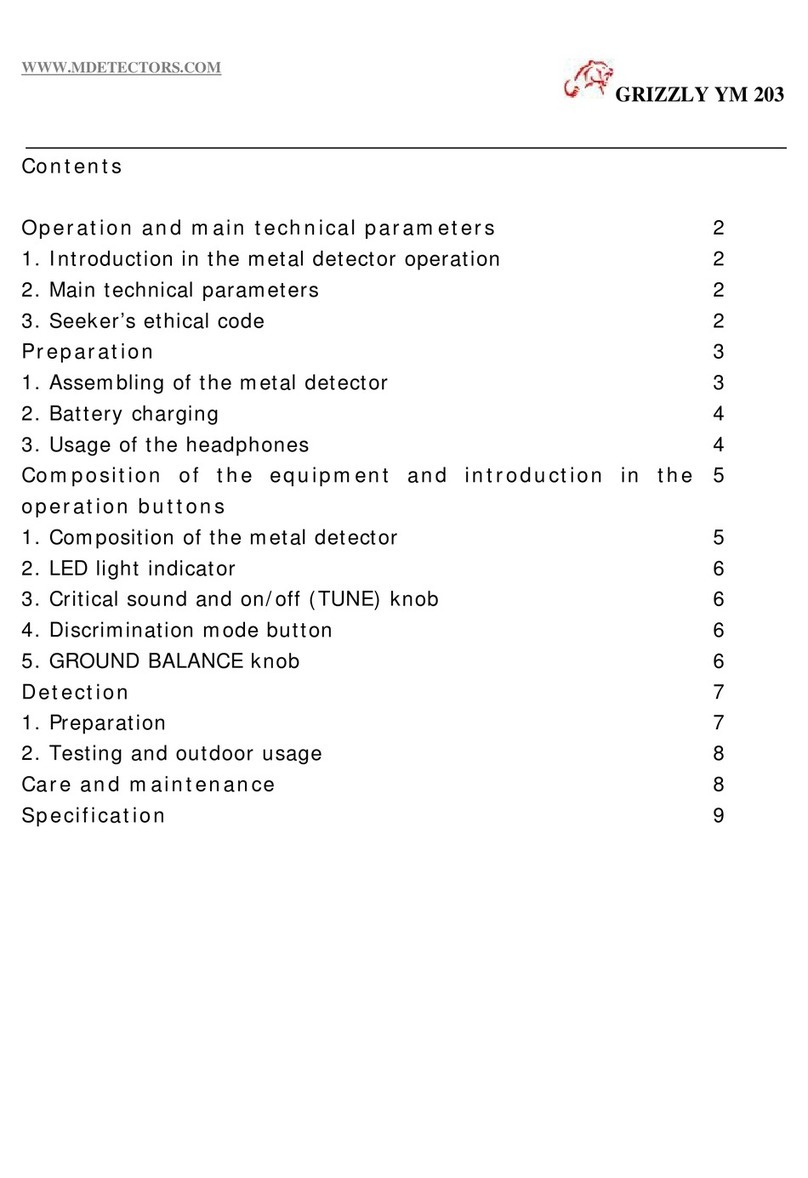
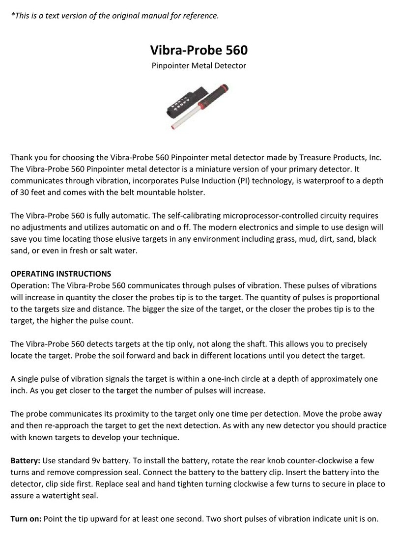
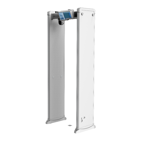
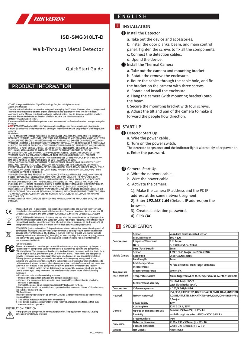
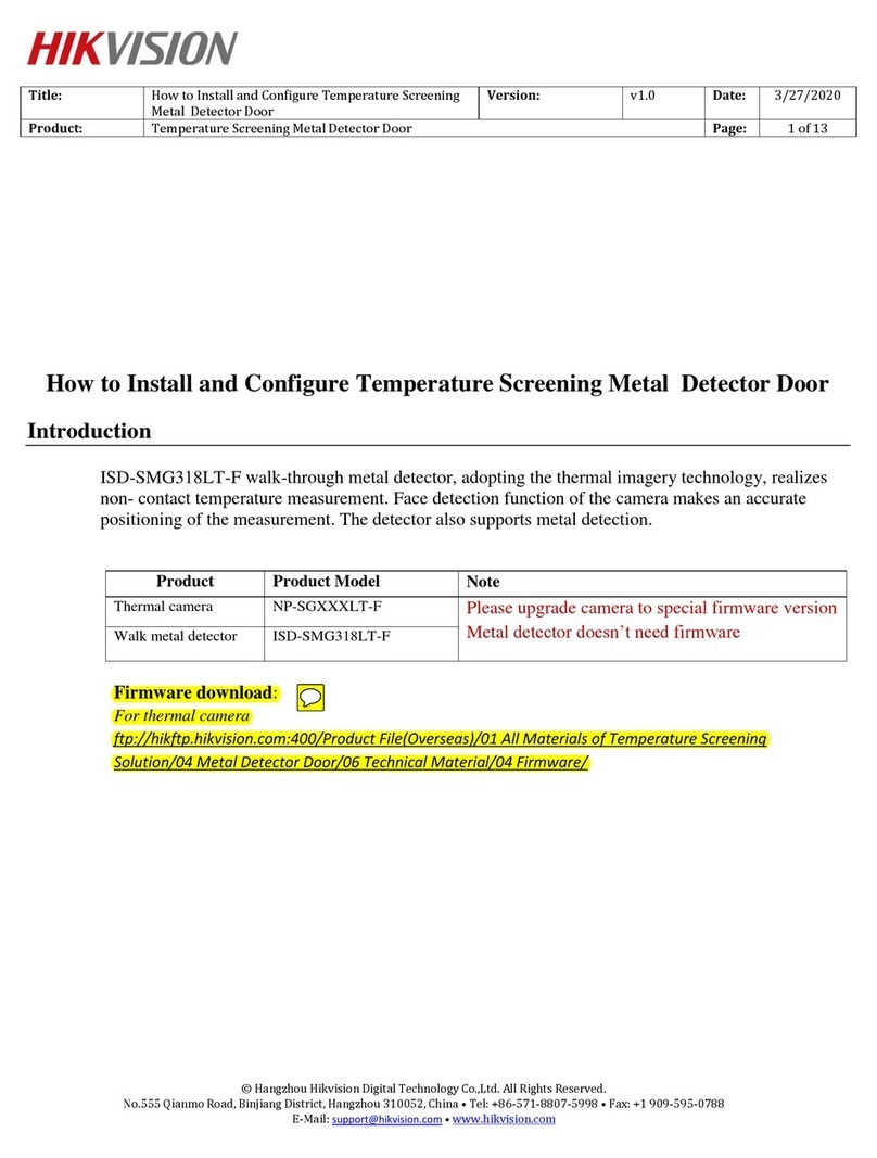
HIK VISION ISD-SMG318LT-D User manual

ISD-SMG318LT-D
Walk-Through Metal Detector
User Manual

1
Legal Information
About this Manual
The Manual includes instructions for using and managing the Product. Pictures, charts, images and all other information hereinafter
are for description and explanation only. The information contained in the Manual is subject to change, without notice, due to
firmware updates or other reasons. Please find the latest version of this Manual at the Hikvision website
(https://www.hikvision.com/).
Please use this Manual with the guidance and assistance of professionals trained in supporting the Product.
Trademarks
and other Hikvision's trademarks and logos are the properties of Hikvision in various
jurisdictions.
Other trademarks and logos mentioned are the properties of their respective owners.
Disclaimer
TO THE MAXIMUM EXTENT PERMITTED BY APPLICABLE LAW, THIS MANUAL AND THE PRODUCT DESCRIBED, WITH ITS HARDWARE,
SOFTWARE AND FIRMWARE, ARE PROVIDED “AS IS” AND “WITH ALL FAULTS AND ERRORS”. HIKVISION MAKES NO WARRANTIES,
EXPRESS OR IMPLIED, INCLUDING WITHOUT LIMITATION, MERCHANTABILITY, SATISFACTORY QUALITY, OR FITNESS FOR A
PARTICULAR PURPOSE. THE USE OF THE PRODUCT BY YOU IS AT YOUR OWN RISK. IN NO EVENT WILL HIKVISION BE LIABLE TO YOU
FOR ANY SPECIAL, CONSEQUENTIAL, INCIDENTAL, OR INDIRECT DAMAGES, INCLUDING, AMONG OTHERS, DAMAGES FOR LOSS OF
BUSINESS PROFITS, BUSINESS INTERRUPTION, OR LOSS OF DATA, CORRUPTION OF SYSTEMS, OR LOSS OF DOCUMENTATION,
WHETHER BASED ON BREACH OF CONTRACT, TORT (INCLUDING NEGLIGENCE), PRODUCT LIABILITY, OR OTHERWISE, IN CONNECTION
WITH THE USE OF THE PRODUCT, EVEN IF HIKVISION HAS BEEN ADVISED OF THE POSSIBILITY OF SUCH DAMAGES OR LOSS.
YOU ACKNOWLEDGE THAT THE NATURE OF INTERNET PROVIDES FOR INHERENT SECURITY RISKS, AND HIKVISION SHALL NOT TAKE
ANY RESPONSIBILITIES FOR ABNORMAL OPERATION, PRIVACY LEAKAGE OR OTHER DAMAGES RESULTING FROM CYBER-ATTACK,
HACKER ATTACK, VIRUS INSPECTION, OR OTHER INTERNET SECURITY RISKS; HOWEVER, HIKVISION WILL PROVIDE TIMELY TECHNICAL
SUPPORT IF REQUIRED.
YOU AGREE TO USE THIS PRODUCT IN COMPLIANCE WITH ALL APPLICABLE LAWS, AND YOU ARE SOLELY RESPONSIBLE FOR ENSURING
THAT YOUR USE CONFORMS TO THE APPLICABLE LAW. ESPECIALLY, YOU ARE RESPONSIBLE, FOR USING THIS PRODUCT IN A MANNER
THAT DOES NOT INFRINGE ON THE RIGHTS OF THIRD PARTIES, INCLUDING WITHOUT LIMITATION, RIGHTS OF PUBLICITY,
INTELLECTUAL PROPERTY RIGHTS, OR DATA PROTECTION AND OTHER PRIVACY RIGHTS. YOU SHALL NOT USE THIS PRODUCT FOR ANY
PROHIBITED END-USES, INCLUDING THE DEVELOPMENT OR PRODUCTION OF WEAPONS OF MASS DESTRUCTION, THE DEVELOPMENT
OR PRODUCTION OF CHEMICAL OR BIOLOGICAL WEAPONS, ANY ACTIVITIES IN THE CONTEXT RELATED TO ANY NUCLEAR EXPLOSIVE
OR UNSAFE NUCLEAR FUEL-CYCLE, OR IN SUPPORT OF HUMAN RIGHTS ABUSES.
IN THE EVENT OF ANY CONFLICTS BETWEEN THIS MANUAL AND THE APPLICABLE LAW, THE LATER PREVAILS.

2
Regulatory Information
FCC Information
Please take attention that changes or modification not expressly approved by the party responsible for compliance could void the
user’s authority to operate the equipment.
FCC compliance: This equipment has been tested and found to comply with the limits for a Class A digital device, pursuant to part 15
of the FCC Rules. These limits are designed to provide reasonable protection against harmful interference when the equipment is
operated in a commercial environment. This equipment generates, uses, and can radiate radio frequency energy and, if not installed
and used in accordance with the instruction manual, may cause harmful interference to radio communications. Operation of this
equipment in a residential area is likely to cause harmful interference in which case the user will be required to correct the
interference at his own expense.
FCC Conditions
This device complies with part 15 of the FCC Rules. Operation is subject to the following two conditions:
1. This device may not cause harmful interference.
2. This device must accept any interference received, including interference that may cause undesired operation.
EU Conformity Statement
This product and - if applicable - the supplied accessories too are marked with "CE" and comply therefore with the
applicable harmonized European standards listed under the EMC Directive 2014/30/EU, the LVD Directive 2014/35/EU,
the RoHS Directive 2011/65/EU.
2012/19/EU (WEEE directive): Products marked with this symbol cannot be disposed of as unsorted municipal waste in
the European Union. For proper recycling, return this product to your local supplier upon the purchase of equivalent
new equipment, or dispose of it at designated collection points. For more information see: www.recyclethis.info
2006/66/EC (battery directive): This product contains a battery that cannot be disposed of as unsorted municipal waste
in the European Union. See the product documentation for specific battery information. The battery is marked with this
symbol, which may include lettering to indicate cadmium (Cd), lead (Pb), or mercury (Hg). For proper recycling, return
the battery to your supplier or to a designated collection point. For more information see: www.recyclethis.info
BATTERY WARNING
1. Do not ingest battery, Chemical Burn Hazard
2. Keep new and used batteries away from the children.
3. If the battery compartment does not close securetyly, stop using the product and keep it away from children.
4. This product contains a coin / button cell battery. If the coin / button cell battery is swallowed, it can cause severe internal
burns in just 2 hours and lead to death.
5. If you think batteries might have been swallowed or placed inside any part of the body, seek immediate medical attention.
BATTERY CAUTION
1. Risk of fire or explosion if the battery is replaced by an incorrect type.
2. Improper replacement of the battery with an incorrect type may defeat a safeguard (for example, in the case of some lithium
battery types).
3. Do not dispose of the battery into fire or a hot oven, or mechanically crush or cut the battery, which may result in an
explosion.
4. Do not leave the battery in an extremely high temperature surrounding environment, which may result in an explosion or the
leakage of flammable liquid or gas.

3
5. Do not subject the battery to extremely low air pressure, which may result in an explosion or the leakage of flammable liquid
or gas.
6. Dispose of used batteries according to the instructions
7. The equipment is not suitable for use in locations where children are likely to be present.
INSTALLATION CAUTION
1. The additional force shall be equal to three times the weight of the equipment but not less than 50N. The equipment and its
associated mounting means shall remain secure during the installation. After the installation, the equipment, including any
associated mounting plate, shall not be damaged.
2. This equipment is not suitable for use in locations where children are likely to be present.

4
Symbol Conventions
The symbols that may be found in this document are defined as follows.
Symbol Description
Danger Indicates a hazardous situation which, if not avoided, will or could result in death or serious
injury.
Caution Indicates a potentially hazardous situation which, if not avoided, could result in equipment
damage, data loss, performance degradation, or unexpected results.
Note Provides additional information to emphasize or supplement important points of the main
text.

5
Safety Instruction
These instructions are intended to ensure that user can use the product correctly to avoid danger or property loss.
Laws and Regulations
● Use of the product must be in strict compliance with the local electrical safety regulations.
Transportation
● Keep the device in original or similar packaging while transporting it.
● Keep all wrappers after unpacking them for future use. In case of any failure occurred, you need to return the device to the factory
with the original wrapper. Transportation without the original wrapper may result in damage on the device and the company shall
not take any responsibilities.
● Do not drop the product or subject it to physical shock. Keep the device away from magnetic interference.
Power Supply
● Input voltage should meet the Limited Power Source (Detector: 12 VDC, camera: 12 VDC, 24 VAC, or PoE(802.3af) according to
the IEC61010-1 standard. Please refer to technical specifications for detailed information.
● Make sure the plug is properly connected to the power socket.
● DO NOT connect multiple devices to one power adapter, to avoid over-heating or fire hazards caused by overload.
Battery
● Improper use or replacement of the battery may result in explosion hazard. Replace with the same or equivalent type only. Dispose
of used batteries in conformance with the instructions provided by the battery manufacturer.
● The built-in battery cannot be dismantled. Please contact the manufacture for repair if necessary.
● For long-term storage of the battery, make sure it is fully charged every half year to ensure the battery quality. Otherwise, damage
may occur.
Maintenance
● If the product does not work properly, please contact your dealer or the nearest service center. We shall not assume any
responsibility for problems caused by unauthorized repair or maintenance.
● Wipe the device gently with a clean cloth and a small quantity of ethanol, if necessary.
● If the equipment is used in a manner not specified by the manufacturer, the protection provided by the device may be impaired.
Using Environment
● Make sure the running environment meets the requirement of the device. The operating temperature shall be -10°C to 55°C (walk
through metal door), 5°C to 40°C (speed dome), and the operating humidity shall be 95% or less, no condensing.
● DO NOT expose the device to high electromagnetic radiation or dusty environments.
● DO NOT aim the lens at the sun or any other bright light.
Emergency
● If smoke, odor, or noise arises from the device, immediately turn off the power, unplug the power cable, and contact the service
center.
Manufacture Address
No.555 Qianmo Road, Binjiang District, Hangzhou 310052, China
Hangzhou Hikvision Digital Technology Co.,Ltd

6
Contents
Chapter 1 Over View .................................................................................................................. 9
System Description ................................................................................................................... 9
Functions ................................................................................................................................ 10
Key Features ........................................................................................................................... 10
Metal Detection Features ...................................................................................................... 10
Thermal Imaging Features ..................................................................................................... 10
Chapter 2 Installation ............................................................................................................... 12
Installation Environment ........................................................................................................ 12
2.1.1 Fixed Metal Object ........................................................................................................ 12
2.1.2 Ground Vibration........................................................................................................... 12
2.1.3 Moving Metal Object .................................................................................................... 12
2.1.4 Radiated Electronic Interference .................................................................................. 13
2.1.5 Conducting Electronic Interference .............................................................................. 13
Side-by-Side Installation ......................................................................................................... 14
Installation and Wiring ........................................................................................................... 14
Chapter 3 Calibration................................................................................................................ 17
Principle .................................................................................................................................. 17
Factory Settings ...................................................................................................................... 17
Calibration Progress ............................................................................................................... 17
Chapter 4 Metal Detector Local Configuration ........................................................................... 20
Chapter 5 Thermal Camera Configuration ................................................................................. 21
Description of Thermal Camera ............................................................................................. 21
5.1.1 Brief Description ........................................................................................................... 21
5.1.2 Function ........................................................................................................................ 21
Device Activation and Accessing ............................................................................................ 22
5.2.1 Activate the Device via SADP ........................................................................................ 22
5.2.2 Activate the Device via Browser.................................................................................... 22
5.2.3 Login .............................................................................................................................. 23
Temperature Measurement ................................................................................................... 24
5.3.1 Notice ............................................................................................................................ 24
5.3.2 Automatic Thermography ............................................................................................. 24
5.3.3 Manual Thermography .................................................................................................. 28
5.3.4 Measure Body Temperature ......................................................................................... 28
Body Thermography ............................................................................................................... 29
5.4.1 Set Body Thermography Parameters ............................................................................ 29
5.4.2 Set Body Thermography ................................................................................................ 30
5.4.3 Set Face Capture ........................................................................................................... 31
Event and Alarm ..................................................................................................................... 33
5.5.1 Set Motion Detection .................................................................................................... 33
5.5.2 Set Video Tampering Alarm........................................................................................... 34
5.5.3 Set Alarm Input ............................................................................................................. 35

7
5.5.4 Set Exception Alarm ...................................................................................................... 36
5.5.5 Detect Audio Exception ................................................................................................. 36
Arming Schedule and Alarm Linkage ..................................................................................... 37
5.6.1 Set Arming Schedule ..................................................................................................... 37
5.6.2 Linkage Method Settings ............................................................................................... 37
Live View ................................................................................................................................ 41
5.7.1 Live View Parameters .................................................................................................... 41
5.7.2 Set Transmission Parameters ........................................................................................ 43
Video and Audio ..................................................................................................................... 45
5.8.1 Video Settings ............................................................................................................... 45
5.8.2 Display Settings ............................................................................................................. 48
5.8.3 OSD ................................................................................................................................ 54
5.8.4 Set Privacy Mask ........................................................................................................... 54
5.8.5 8.5 Overlay Picture ........................................................................................................ 54
5.8.6 Set Manual DPC (Defective Pixel Correction) ................................................................ 55
5.8.7 Set Picture in Picture ..................................................................................................... 55
Video Recording and Picture Capture .................................................................................... 56
5.9.1 Storage Settings............................................................................................................. 56
5.9.2 Video Recording ............................................................................................................ 58
5.9.3 Capture Configuration ................................................................................................... 59
Network Settings .................................................................................................................. 61
5.10.1 TCP/IP .......................................................................................................................... 61
5.10.2 Port .............................................................................................................................. 62
5.10.3 Port Mapping .............................................................................................................. 62
5.10.4 Multicast ..................................................................................................................... 63
5.10.5 SNMP ........................................................................................................................... 63
5.10.6 Access to Device via Domain Name ............................................................................ 63
5.10.7 Access to Device via PPPoE Dial Up Connection ......................................................... 64
5.10.8 Enable Hik-Connect Service on Camera ...................................................................... 65
5.10.9 Set ISUP ....................................................................................................................... 66
5.10.10 Set ONVIF .................................................................................................................. 66
5.10.11 Set HTTP Listening ..................................................................................................... 66
System and Security ............................................................................................................. 68
5.11.1 View Device Information ............................................................................................. 68
5.11.2 Search and Manage Log .............................................................................................. 68
5.11.3 Import and Export Configuration File ......................................................................... 68
5.11.4 Export Diagnose Information ...................................................................................... 68
5.11.5 Reboot ......................................................................................................................... 68
5.11.6 Restore and Default..................................................................................................... 68
5.11.7 Upgrade ....................................................................................................................... 69
5.11.8 View Open Source Software License ........................................................................... 69
5.11.9 Time and Date ............................................................................................................. 69
5.11.10 Set RS-232 ................................................................................................................. 70
5.11.11 Set RS-485 ................................................................................................................. 70

8
5.11.12 Set Same Unit ............................................................................................................ 71
5.11.13 Security ..................................................................................................................... 71
5.11.14 User and Account ...................................................................................................... 74
Configuring via Web Client ................................................................................................... 76
5.12.1 Parameters Settings .................................................................................................... 76
5.12.2 Operations ................................................................................................................... 77
Appendix ................................................................................................................................. 78
FAQ ......................................................................................................................................... 78
Common Material Emissivity Reference ................................................................................ 78
Detector Zone Schematic Diagram ........................................................................................ 80
Detection Sensitivity for Guns ................................................................................................ 81
Dimension .............................................................................................................................. 83
Detection Program ................................................................................................................. 84
Specification ........................................................................................................................... 85

9
Chapter 1 Over View
System Description
Walk-through metal detector, adopting the thermographic technology, realizes contactless temperature screening. AI detection
function of the camera makes an accurate positioning of the skin-surface. The detector also supports metal detection.
This equipment is used to detect the metal items carried by personnel through the detection door, mainly used for weapons detection.
The typical application environment including: ·
Airport port: passenger check; ·
Court: visitors check; ·
Prison: visitors check; ·
Meetings, public buildings, sports events: access control; ·
Power plant: employees and visitors check; ·
Factory: anti-theft; ·
Hotels, restaurants, entertainment venues, dance halls: visitors check
There is no health hazard will be caused to the pregnant woman, people wearing a pacemaker, or to any other person passing through
the metal detector when the procedure is followed.

10
Functions
Supports network transmission, which makes it able to report passenger flow statistics /metal detection data as well as to
configure parameters remotely.
Non-contact temperature measurement: skin-surface temperature screening with accurately personnel matching.
Temperature accuracy:±0.5 ℃ , detection distance: 0.5 to 1.5 m, target height: 1.45 m to 1.85 m
Temperature filtering: adjustable temperature threshold. An over-threshold temperature will trigger the audible strobe light
Counting display: displays the walk-through people number, metal alarm times, real time temperature, number of people in
abnormal temperature
Metal detection: metal likes a clip
Multi-Area alarm: Indicates the metal position on the body. Max. 18 areas
Modularized component: easy transmission and installation
Key Features
Online Report: Supports network transmission, which makes the detector able to report passenger flow statistics and metal
detection data
Remote Configuration: Supports configuring remotely via web client
HCP Accessing: Supports accessing to the HCP platform to count the entry and exit people, which realize the function of limit
flow alarm and statistic report
Detection accuracy: metal in the size like a coin (diameter: 25 mm) is detectable on the middle of the detector. Goods like
Belt buckle can be excluded. Copper, aluminum, and zinc (over 150 g) , controlled knife, and gun are detectable
Password Protection: Mandatory default password changing strategy for protecting password security
Anti-interference: multiple detector can work abreast at the same time
Multi-area alarm: Indicates the metal position on the body. Max. 18 areas
Frequency settings: 100 frequencies can be set, and different ring tone for different frequency
Sensitivity Settings: 255 level of sensitivity can be set
People counting: display the number of walk-through people and people in alarm
Positioning LED: LED on the entry side of the plank indicating the position of the prohibited goods.7 inch LCD touch screen for
easy operation
Storing sensitivity parameters for different scenes for shortcut settings.
Material: PVC shell
Smart Functions
Temperature exception detection
Linkage for audible alarm
Linkage of white strobe light alarm
Detector configuration via web client

11
Thermal Imaging Functions
Uncooled sensor, resolution: 160 x 120
Supports AGC4.0, DDE, and 3DNR
Supports dual-light fusion image
Supports visible light and thermal imaging frame over lay
15 pseudo colors: white, black, red, etc.
Visible Light Functions
4 MP, 1/2.7 “ CMOS, Max. resolution: 2688×1520@25fps
Supports low bit rate, low latency and ROI
Independent settings for day or night condition
System Functions
Dual-channel, single IP
Dual-streaming
PoE power supply
IP66 protective level
Operation temperature: 5℃ to 40℃, <95% RH
Interfaces
10M/100M self-adapting network interface
Micro SD/Micro SDHC/Micro SDXC card (128G/256G) slot
1-ch alarm input/output
1-ch audio input/output
1-ch 12 VDC power input
Security
Security verification, such as HTTPS, supports license creating
Three level of users, IP address filtering, user and password authentication

12
Chapter 2 Installation
Installation Environment
In order to ensure the optimal operation of the detector and the maximum flow of people, the following important factors are taken
into account to minimize the impacts made by different interference sources.
Large fixed or immovable metal objects should be at least 10cm (4in) away from the detector (to detect large metal objects). This has
less impact on the sensitivity, but may make the detector more susceptible to vibration.
The ground should be flat, with strong support, to prevent vibration, especially when there are vibration metal structures under the
ground.
The large metal objects moving outside the detector shall be kept at least at a distance of 0.5-2m (20-79in) from the detector to avoid
false alarm. According to the size of the metal object, the distance between the required moving metal object and the detector may
different.

13
The maximum distance between the electronic interference source and the receiving coil should be maximum. The recommended
minimum distance is 0.5-4m (20-157in). However, the actual distance should vary according to the specific situation.
The Interference may be caused by electronic control panel, radio equipment and computer, image display, high-power motor and
transformer, AC wire, transistor control circuit, flash fluorescent lamp, ARC welding equipment, etc.
Connecting the power cable to a circuit that is not connected with other large load equipment may cause voltage shock.
The recommended min. distance away from the interference source:
A. With fixed metal object
B. No moving metal object is allowed
C. No electronic interference source is allowed

14
Note: Make the Receiving Coil (RX) away from the interference source. Make sure the interference level displayed on the environment
inspection indicator is less than 2.
Side-by-Side Installation
Side-by-side operation refers to the operation of two or more detectors in close proximity to each other. With side-by-side operation,
the detector may interfere with each other. The level of interference depends on the distance between the detector and their
operating frequency and sensitivity.
The detector has different working frequency selection. The operating frequency of each detector should be different
Installation and Wiring
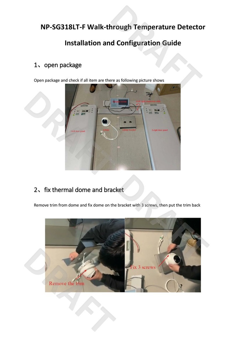
1. Take out the device and accessories.
2. Install the door planks, beam, and main control panel. Tighten the screws to fix all the components.
3. Connect the detection cables.

15
4. Take out the camera and mounting bracket.
5. Rotate and remove the enclosure.
6. Route the cables through the cable hole, and fix the bracket on the camera with three screws.
7. Rotate and install the enclosure.
8. Hang the camera (with mounting bracket) onto the beam.
9. Secure the mounting bracket with four screws.

16
10. Adjust the camera to make it forward the people flow direction.
11. Upend the device.
12. (If required) Fix the detector on the floor.
a) Mark the screw location on the floor.
b) Drill the screw holes.
c) Insert the extension bolt in the screw holes.
d) Fix the detector on the floor with four HWA5 *60 self tapping screws.

17
Chapter 3 Calibration
The purpose of the calibration is to enable the operational characteristics of the detector to meet the requirements of the security
level. Calibration the detector before the security checkpoint starts work. Prior to calibration, probe requirements should be
determined, for example, what is most dangerous goods likely to be detected. The detector should be calibrated with a reference
representing the danger level.
Principle
1. Select the Operating Frequency
Select the interference that has the lowest level of background (up to 1 to 2 red light flashing)
2. Set the Detection Sensitivity
Set the security level first, and then the zone sensitivity. Set proper parameters, as a high detection sensitivity may affect the anti-
interference of the detector.
3. Choose
Set the detection program that generates the lowest metal signal when walk-through the detector with harmless items.
4. Test
Daily inspection:
- Calibration with test objects calibration
- Detective door mechanical fixation
Factory Settings
The manufacturer setting is a good starting for calibration. The calibration must be carried out at the installation place. Due to the
different installation environment, the final detection parameters will vary slightly depending on the installation place.
The parameters set by the manufacturer are defined in the laboratory environment and may differ significantly from the actual
installation environment.
Calibration Progress
1. Select operation frequency
2. Set detection sensitivity: safety level and zone sensitivity
3. Test
I. Select Frequency:
Select an appropriate operating frequency (with a sufficiently low level of background interference) and start the calibration.
1 Install the detector according to the instruction.
2 Make sure that the tester are not wearing any clothing containing metal components.
II. Set Detector Sensitivity
The purpose of the detection sensitivity settings is to find the lowest sensitivity settings so that the test object can still be detected
with low sensitivity under the current detection program. It is possible to achieve a high pass rate by minimizing the useless alarm

18
caused by non-hazardous substances.
Sensitivity settings will also affect the anti-interference of the detector. It is not recommended to use a sensitivity that is too high for
the operation place.
In order to adjust the detection sensitivity, the test object should be placed in different positions on the body in different ways and
carried through the detector.
Steps:
1. Define the overall sensitivity, which can be adjusted manually (except for ankle height).
2. Define ankle height sensitivity (zone sensitivity). Manual ground sensitivity adjustment is available.
3. For different installation place, the amount and orientation of metal in the ground where the probe door is located may vary.
The required ground height sensitivity settings varies according to the place situation.
Set Zone Sensitivity
After adjusting the safety level, fix the key test item in the ankle position and carry the item through the detector. Walk through the
detector in at least two ways: A. Step one foot with the test item in the center of the detector. B. Step over the center of the detector
with one foot with the test item.

19
III. Test
Daily inspection:
- Calibration with test objects calibration
- Detective door mechanical fixation
Other manuals for ISD-SMG318LT-D
1
Table of contents
Other HIK VISION Metal Detector manuals
Popular Metal Detector manuals by other brands

White’s Electronics
White’s Electronics coinmaster 3900/D Professional Operator's manual

Mikron
Mikron NRG 110 User's operating manual

Loma
Loma X5c operating instructions

Makro Detector
Makro Detector Deep Hunter user manual

Grizzly
Grizzly TWINS METAL DETECTOR user guide

Minelab
Minelab Sovereign Elite Instructoin manual