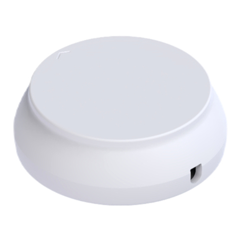
HIK VISION DS-PR1-60 User manual

DS-PR1-60
Security Radar
User Manual

DS-PR1-60 User Manual
UM DS-PR1-60 090920NA 2
© 2020 Hangzhou Hikvision Digital Technology Co., Ltd. All rights reserved.
About this Manual
The Manual includes instructions for using and managing the Product. Pictures, charts, images and all other
information hereinafter are for description and explanation only. The information contained in the Manual is
subject to change, without notice, due to firmware updates or other reasons. Please find the latest version of
this Manual at the Hikvision Website ( https:// www.hikvision.com/ ).
Please use this Manual with the guidance and assistance of professionals trained in supporting the Product.
Trademarks
and other Hikvision trademarks and logos are the properties of Hikvision in various
jurisdictions.
Other trademarks and logos mentioned are the properties of their respective owners.
Disclaimer
TO THE MAXIMUM EXTENT PERMITTED BY APPLICABLE LAW, THIS MANUAL AND THE PRODUCT DESCRIBED,
WITH ITS HARDWARE, SOFTWARE AND FIRMWARE, ARE PROVIDED “AS IS” AND “WITH ALL FAULTS AND
ERRORS.” HIKVISION MAKES NO WARRANTIES, EXPRESS OR IMPLIED, INCLUDING WITHOUT LIMITATION,
MERCHANTABILITY, SATISFACTORY QUALITY, OR FITNESS FOR A PARTICULAR PURPOSE. THE USE OF THE
PRODUCT BY YOU IS AT YOUR OWN RISK. IN NO EVENT WILL HIKVISION BE LIABLE TO YOU FOR ANY SPECIAL,
CONSEQUENTIAL, INCIDENTAL, OR INDIRECT DAMAGES, INCLUDING, AMONG OTHERS, DAMAGES FOR LOSS
OF BUSINESS PROFITS, BUSINESS INTERRUPTION, OR LOSS OF DATA, CORRUPTION OF SYSTEMS, OR LOSS OF
DOCUMENTATION, WHETHER BASED ON BREACH OF CONTRACT, TORT (INCLUDING NEGLIGENCE), PRODUCT
LIABILITY, OR OTHERWISE, IN CONNECTION WITH THE USE OF THE PRODUCT, EVEN IF HIKVISION HAS BEEN
ADVISED OF THE POSSIBILITY OF SUCH DAMAGES OR LOSS.
YOU ACKNOWLEDGE THAT THE NATURE OF INTERNET PROVIDES FOR INHERENT SECURITY RISKS, AND
HIKVISION SHALL NOT TAKE ANY RESPONSIBILITIES FOR ABNORMAL OPERATION, PRIVACY LEAKAGE OR
OTHER DAMAGES RESULTING FROM CYBER-ATTACK, HACKER ATTACK, VIRUS INSPECTION, OR OTHER
INTERNET SECURITY RISKS; HOWEVER, HIKVISION WILL PROVIDE TIMELY TECHNICAL SUPPORT IF REQUIRED.
YOU AGREE TO USE THIS PRODUCT IN COMPLIANCE WITH ALL APPLICABLE LAWS, AND YOU ARE SOLELY
RESPONSIBLE FOR ENSURING THAT YOUR USE CONFORMS TO THE APPLICABLE LAW. ESPECIALLY, YOU ARE
RESPONSIBLE, FOR USING THIS PRODUCT IN A MANNER THAT DOES NOT INFRINGE ON THE RIGHTS OF THIRD
PARTIES, INCLUDING WITHOUT LIMITATION, RIGHTS OF PUBLICITY, INTELLECTUAL PROPERTY RIGHTS, OR DATA
PROTECTION AND OTHER PRIVACY RIGHTS. YOU SHALL NOT USE THIS PRODUCT FOR ANY PROHIBITED END-
USES, INCLUDING THE DEVELOPMENT OR PRODUCTION OF WEAPONS OF MASS DESTRUCTION, THE
DEVELOPMENT OR
PRODUCTION OF CHEMICAL OR BIOLOGICAL WEAPONS, ANY ACTIVITIES IN THE CONTEXT RELATED TO ANY
NUCLEAR EXPLOSIVE OR UNSAFE NUCLEAR FUEL-CYCLE, OR IN SUPPORT OF HUMAN RIGHTS ABUSES.
IN THE EVENT OF ANY CONFLICTS BETWEEN THIS MANUAL AND THE APPLICABLE LAW, THE LATTER PREVAILS.
DS-PR1-60 User Manual
UM DS-PR1-60 090920NA 3
Symbol Conventions
The symbols that may be found in this document are defined as follows.
Symbol Description
Danger
Indicates a hazardous situation which, if not avoided, will or could result in
death or serious injury.
Caution
Indicates a potentially hazardous situation which, if not avoided, could result in
equipment damage, data loss, performance degradation, or unexpected
results.
Provides additional information to emphasize or supplement important points
of the main text.

DS-PR1-60 User Manual
UM DS-PR1-60 090920NA 4
Contents
Chapter 1 Access to Client Software/Web Client ........................................................................................ 7
Chapter 2 Activation .................................................................................................................................. 8
4.1 Activate Device via Client Software........................................................................................................... 8
4.2 Activate via SADP ...................................................................................................................................... 9
4.3 Activate Device via Web Browser............................................................................................................ 10
Chapter 3 Wired Network Settings ........................................................................................................... 11
Chapter 4 Radar Settings.......................................................................................................................... 12
4.1 Radar Settings in the Web Client............................................................................................................. 12
4.1.1 Add Map......................................................................................................................................... 12
4.1.2 Add Zones....................................................................................................................................... 13
4.1.3 Add Trigger Line.............................................................................................................................. 15
4.2 Radar Settings in the Client Software ..................................................................................................... 17
4.2.1 Add Map......................................................................................................................................... 17
4.2.2 Add the Radar to the Map ............................................................................................................. 18
4.2.3 Add Radar Zone.............................................................................................................................. 21
4.2.4 Add Trigger Line.............................................................................................................................. 24
4.2.5 Other Auxiliary Functions............................................................................................................... 26
Chapter 5 Camera Linkage Settings .......................................................................................................... 27
5.1 Set Speed Dome Initial Position.............................................................................................................. 27
5.2 Link the Camera to the Radar.................................................................................................................. 28
5.3 Calibrate Camera..................................................................................................................................... 29
5.3.1 One Point Calibration..................................................................................................................... 33
5.3.2 Multipoint Calibration.................................................................................................................... 36
5.4 Set Park Function for Linked Camera ...................................................................................................... 38
5.5 Link the Camera to the Zone................................................................................................................... 40

DS-PR1-60 User Manual
UM DS-PR1-60 090920NA 5
5.6 Pop-up Alarm Notification ...................................................................................................................... 41
Chapter 6 Calibrating via Radar Calibration Tool....................................................................................... 44
6.1 Download and Registration ..................................................................................................................... 44
6.2 Add Device .............................................................................................................................................. 44
6.3 One-Point Calibration.............................................................................................................................. 45
6.4 Multi-Point Calibration............................................................................................................................ 46
Chapter 7 Set Record and Storage Settings............................................................................................... 48
1.1 Set Storage Settings................................................................................................................................. 48
1.1.1 Set Storage Schedule via Storage Server ....................................................................................... 48
1.1.2 Set Storage Schedule via NVR ........................................................................................................ 49
1.2 Set Tracking Strategy............................................................................................................................... 49
Chapter 8 Alarm Settings ......................................................................................................................... 50
8.1 Alarm Center ........................................................................................................................................... 50
8.2 Notification Push..................................................................................................................................... 50
8.3 Set Zone................................................................................................................................................... 51
8.4 Set Alarm Output .................................................................................................................................... 51
8.5 Set Arming/Disarming Schedule ............................................................................................................. 52
8.6 Set Motion Speed.................................................................................................................................... 53
8.7 Video Tracking Switch Settings................................................................................................................ 53
Chapter 9 Set Radar Advanced Function................................................................................................... 54
9.1 Set Master-Slave Tracking Settings......................................................................................................... 54
9.2 Set Detection Angle and Range............................................................................................................... 54
9.3 Set Scene Mode and Sensitivity .............................................................................................................. 54
9.4 Set Frequency Range Settings................................................................................................................. 55
9.5 Track Settings .......................................................................................................................................... 55
Chapter 10 View Alarm Information......................................................................................................... 56

DS-PR1-60 User Manual
UM DS-PR1-60 090920NA 6
Chapter 11 System Management ............................................................................................................. 57
11.1 Set Time.......................................................................................................................................... 57
11.2 Manage User .................................................................................................................................. 57
11.3 System Maintenance...................................................................................................................... 58
11.4 View Device Information................................................................................................................ 58
11.5 Search Log ...................................................................................................................................... 58
11.6 Enabling Remote Debugging .......................................................................................................... 58
11.7 LED Status....................................................................................................................................... 59
Appendix A. Radar Mounting Height Recommendation............................................................................ 60
Appendix B. Formatting Description......................................................................................................... 61
Appendix C. Indicator Description ............................................................................................................ 62
Appendix D. FAQ...................................................................................................................................... 63
D.1 How to Achieve an Optimum Detection Range? .................................................................................... 63
D.2 How To Solve Radar Not Shown in Device List on Radar Page? ............................................................. 63
D.3 How To Adjust Sensitivity to Avoid False Alarms? .................................................................................. 63
D.4 How To Raise the Camera Tracking Precision?........................................................................................ 64
D.5 How to Solve No Reference Point on Frame While Setting Speed Dome Initial Position?..................... 64
D.6 What Is the Reason that Failed to Draw a Zone Automatically?............................................................. 65
D.7 What Makes a Failed Arming? ................................................................................................................ 66
D.8 Why Is It Required to Remove Reflective Objects from theRadar Area? ............................................... 66
D.9 Why Is the Camera Unable to Track the Target? ..................................................................................... 66
D.10 Common Mistakes of Calibrating Camera...................................................................................... 66
Appendix E. Communication Matrix and Device Command....................................................................... 67

DS-PR1-60 User Manual
UM DS-PR1-60 090920NA 7
Chapter 1 Access to Client Software/Web Client
You can log in to the Client Software or the Web client to configure the device’s parameters. You can also
configure the radar’s network parameters, alarm, permission, system, and search logs via the Web client.
You should activate the device the first time it accesses to the network for safety reasons. For details, see
Device Activation.
Access to Client Software
Download and install the iVMS-4200 client software. Register to the software. Enter Device Management →
Device → +Add in the Maintenance and Management list to add the device.
Set the device port no. as 80.
The activation user name and password are used for device login, registration, etc.
After the device is completely added, click to enter the device configuration page. You can configure the
device parameters in this page.
Access to Web Client
After the device is connected to the network, you can search for the device IP address via the iVMS-4200
client software or the SADP software. Input the searched IP address in the address bar in the Web page and
press Enter. Use the activation user name and password to login. You can configure the device parameters in
the Web page.

DS-PR1-60 User Manual
UM DS-PR1-60 090920NA 8
Chapter 2 Activation
In order to protect personal security and privacy and improve the network security level, you must activate
the device the first time you connect the device to a network.
4.1 Activate Device via Client Software
Before You Start
•Get the iVMS-4200 client software from the supplied disk or the official Website at http://
www.hikvision.com/en/. Install the software by following the prompts.
•The device and the PC running the software must be in the same subnet.
1. Run the client software.
2. Enter Device Management → Device in the Maintenance and Management list.
3. Click Online Device.
4. Check the device status from the online device list, and select an inactive device.
5. Click Activate.
6. Create and confirm the admin password of the device.
STRONG PASSWORD RECOMMENDED −We highly recommend that you create a strong password
of your own choosing (using a minimum of eight characters, including at least three of the
following categories: upper case letters, lower case letters, numbers, and special
characters) in order to increase the security of your product. We also recommend that you
reset your password regularly. Especially in high security systems, resetting the password
monthly or weekly can better protect your product.
Proper configuration of all passwords and other security settings is the responsibility of the
installer and/or end-user.
7. Click OK to start activation. Device status will change to Active after successful activation.
8. Edit the device’s IP address.
1) Select a device and click on the online device list.
2) Change the device’s IP address to the same subnet as your computer, and set port number to 80.
3) Enter the device’s admin password, and click OK to complete modification.
9. Optional: Check the device on the online device list, and click Add to add the device to the device list.

DS-PR1-60 User Manual
UM DS-PR1-60 090920NA 9
4.2 Activate via SADP
SADP is a tool to detect, activate, and modify the device’s IP address over the LAN.
Before You Start
•Get the SADP software from the supplied disk or the official Website http:// www.hikvision.com/en/, and
install the SADP according to the prompts.
•The device and the PC that runs the SADP tool should be within the same subnet.
The following steps show how to activate a device and modify its IP address. For batch activation and IP
addresses modification, refer to SADP User Manual for details.
1. Run the SADP software and search the online devices.
2. Find and select your device on the online device list.
3. Input a new password (admin password) and confirm the password.
STRONG PASSWORD RECOMMENDED −We highly recommend that you create a strong password
of your own choosing (using a minimum of eight characters, including at least three of the
following categories: upper case letters, lower case letters, numbers, and special
characters) in order to increase the security of your product. We also recommend that you
reset your password regularly. Especially in high security systems, resetting the password
monthly or weekly can better protect your product.
Proper configuration of all passwords and other security settings is the responsibility of the
installer and/or end-user.
4. Click Activate to start activation. Status of the device becomes Active after successful activation.
5. Modify IP address of the device.
1) Select the device.
2) Change the device IP address to the same subnet as your computer by either modifying the IP address

DS-PR1-60 User Manual
UM DS-PR1-60 090920NA 10
manually or checking Enable DHCP.
3) Input the admin password and click Modify to activate your IP address modification.
4.3 Activate Device via Web Browser
Use a Web browser to activate the device. Use SADP software or PC client to search the online devices to get
the IP address of the device, and activate the device on the Web page.
Before You Start
Make sure your device and your PC connect to the same LAN.
1. Open a Web browser and input the IP address of the device.
If you connect the device to the PC directly, you need to change the IP address of the PC to
the same subnet as the device. The default IP address of the device is 192.0.0.64.
2. Create and confirm the admin password.
STRONG PASSWORD RECOMMENDED −We highly recommend that you create a strong password
of your own choosing (using a minimum of eight characters, including at least three of the
following categories: upper case letters, lower case letters, numbers, and special
characters) in order to increase the security of your product. We also recommend that you
reset your password regularly. Especially in high security systems, resetting the password
monthly or weekly can better protect your product.
Proper configuration of all passwords and other security settings is the responsibility of the
installer and/or end-user.
3. Click OK to complete activation.
4. Edit IP address of the device.
1) Enter IP address modification page.
2) Change IP address.
3) Save the settings.

DS-PR1-60 User Manual
UM DS-PR1-60 090920NA 11
Chapter 3 Wired Network Settings
You can set the device IP address and other network parameters.
Functions varied depending on the model of the device.
1. In the client software, enter Device Management page.
2. Select the device in the Device for Management list, click .
3. Click Communication Parameters → Wired Network Settings to enter thepage.
Figure 3-1 Wired Network Settings Page
4. Set the parameters.
•Automatic Settings: Enable DHCP and set the HTTP port.
•Manual Settings: Disabled DHCP and set IP Address, Subnet Mask, Gateway Address, DNS Server
Address.
•HTTP Port: Default is 80, which is not editable.
5. Optional: Set correct DNS server address if the device needs to visit Hik-Connect server via a domain name.
6. Optional: Set correct DNS server address if the device needs to visit server via a domain name.
7. Click Save.

DS-PR1-60 User Manual
UM DS-PR1-60 090920NA 12
Chapter 4 Radar Settings
You can add zones and set camera tracking parameters for the radar in the client software or a Web client.
4.1 Radar Settings in the Web Client
Edit maps, radars, zones, and trigger lines in a Web client.
Staying on the Radar page for 2 hours without any operation will automatically log out.
Staying nn the Configuration page for five minutes without any operation will
automatically log out.
The Web client’s Radar page cannot receive CID alarms and zone color changes.
4.1.1 Add Map
1. Enter the radar’s IP address and log in.
2. Click Radar to enter the page.
3. Click Edit to enter the editing mode.
4. Click Map Management → Add Map.
The added map should be less than 3 MB.
5. Load a map and click OK.
6. Click Map Management → Edit Scale.
7. Click on the map to draw a straight line, select the end position and click again to complete the drawing.
8. Enter the actual distance between two points.

DS-PR1-60 User Manual
UM DS-PR1-60 090920NA 13
Figure 4-1 Edit Scale
The word range is the predicted distance range of system. You should enter the number in
the this range.
9. Click OK.
10. Adjust the radar position. Drag the sector to make the radar detection area cover the required filed. You
can rotate the sector with the icon on the arc side of the sector.
4.1.2 Add Zones
1. Enter the IP address of the radar and log in.
2. Click Radar to enter the page.
3. Click Edit to enter the editing mode.
4. Optional: Enable Enable Auxiliary in the upper left corner of the map. The target track will appear on the
radar detection area. You can draw a zone with reference to the track. The track clears when disabled.
5. Click Draw Zone Manually, and click the mouse to draw a zone on the radar detection area.
•Zones can overlap, with the priority of the effective overlapping zone being: Disabled Zone>Warning
Zone>Early Warning Zone. That is, Early Warning Zone can contain Warning Zone and Disabled Zone,
and Warning Zone can contain Disabled Zone.
•You can zoom in/out to adjust the size of the displayed radar area.
6. Right-click to complete drawing, and the system will pop up a window. Enter the zone name, and select
Early Warning Zone, Warning Zone, or Disabled Zone as the zonetype.

DS-PR1-60 User Manual
UM DS-PR1-60 090920NA 14
•Early Warning Zone:The early warning zone will identify target that has potential risks in advance and
trigger an alarm, but will not store the alarm track. The early warning zone is green.
•Warning Zone: The warning zone will identify the targets entering the area and trigger the alarm. The
warning zone is orange.
•Disabled Zone: The disabled zone will block the target track into the area. The disabled zone is gray.
7. Click OK.
8. Optional: Modify or delete the zone.
1) Double click on the zone to enter the zone editing mode.
Figure 4-4 Add a Marker
2) Put the cursor on the line of the zone and it will change to a cross, click to add amarker.
3) Drag the marker to change the shape of the zone.
Figure 4-5 Drag a Marker

DS-PR1-60 User Manual
UM DS-PR1-60 090920NA 15
Figure 4-6 Move the Zone
4) Hold to move the zone.
5) Click outside the zone to exit the zone editing mode.
To delete a zone, click in the zone editing mode.
To edit the zone name and the zone type, click in the zone editing mode.
4.1.3 Add Trigger Line
Before You Start
Disarm the radar before adding trigger lines.
1. Enter the IP address of the radar and log in.
2. Click Radar to enter the page.
3. Click Edit to enter the editing mode.
4. Click Draw Trigger Line. You can draw Trigger Line or Dual-trigger Line.
The alarm can be triggered by crossing the Trigger Line according to the trigger line rule; the
alarm can be triggered only after crossing double lines of a Dual-trigger Line according to
the trigger line rule.
Drawing a dual-trigger line that is too tortuous will cause a failure.
5. Draw the trigger line.
1) Click on the radar detection area to draw a trigger line.
2) Select Left -> Right, Left <- Right or Left <-> Right in the pop-up window.
3) Enter the distance between two lines (only for Dual-trigger Line.)
4) Direction determination: Set the starting point as the center of the circle, the trigger line is clockwise to
the right and counterclockwise to the left.

DS-PR1-60 User Manual
UM DS-PR1-60 090920NA 16
5) Up to 4 trigger lines can be drawn.
6) Up to 1 dual-trigger line can be drawn.
7) Trigger line rule: A single arrow -> indicates that the target triggers an alarm when it crosses the trigger
line in the direction of the arrow; a double arrow <-> indicates that the target triggers an alarm when it
crosses the trigger line in any direction.
8) Trigger lines cannot cross each other.
6. Click OK to complete the drawing.
7. Optional: Double click on the trigger line to enter the trigger line editing mode.
Figure 4-8 Add a Marker
•Add a Marker: Click on the line to add a marker.
Figure 4-9 Drag a Marker
•Drag a Marker: Drag a marker on the trigger line to move it.
Figure 4-10 Move the Trigger Line
•Move the Trigger Line: Hold the editing area to move the trigger line.
•Edit: Click to edit the trigger line name, trigger line rule and distance (only for Dual-trigger Line).

DS-PR1-60 User Manual
UM DS-PR1-60 090920NA 17
•Delete: Click to delete the trigger line.
4.2 Radar Settings in the Client Software
Edit radar parameters in client software.
4.2.1 Add Map
1. Click E-map to enter the radar page.
2. Select the radar group, and click Add map to load a map.
Supported picture formats: jpg/png/bmp/jpeg.
Figure 4-11 Add a Map
3. Click OK.
4. Click Edit Scale.
5. Click on the map to draw a straight line, select the end position and click again to complete the drawing.
6. Enter the actual distance between two points.
The gray word range is the predicted distance range of system. You should enter the
number in the this range.

DS-PR1-60 User Manual
UM DS-PR1-60 090920NA 18
Figure 4-12 Edit Scale
7. Click OK.
4.2.2 Add the Radar to the Map
After adding the map, you need to add a radar to the map.
Before You Start
Make sure that you have added the radar (when adding the device, check Import to Group) to the client
software, as well as the map.
Multiple radars need to be added to the same group before they can be added to the same
map.
1. In the E-map page, click Edit in the upper right corner of the map to enter the editingmode.
2. Expand the device group in the left list, and then click and drag the radar onto themap.
3. Adjust the radar position. Drag the radar icon to make the radar detection area cover the required filed.
You can rotate the sector with the icon on the arc side of the sector.
You can drag the red slider in the lower right corner on the map to adjust the range of
displayed map, and click +/- to adjust the size of displayed map. Click to reset the map.

DS-PR1-60 User Manual
UM DS-PR1-60 090920NA 19
4. Optional: Click to delete radar or click to edit radar parameters:
Menu Description
Hot Spot Name Radar name
Hot Spot Color Color of radar name
Hot Spot Icon The default icon cannot be changed
Apply to Other Radar Hot Spots After checking, the changes will be synchronized to other radars.
5. Click Finish in the upper right corner of the map to exit the editing mode, and the radar is fixed.
6. Optional: After exiting the editing mode, click the radar icon and a menu appears above the radar icon.
Figure 4-14 Radar Menu
Menu Description
Arm Open the arming mode of the radar detection area.
If there is a target in the warning zone when arming, a prompt will appear: There are
targets in the zone, enable mandatory arming?, and click OK to arm.
Disarm Close the arming mode of the radar detection area.
Event Search and play back alarm events.
For details, see View Alarm Information.
7. Optional: After exiting the editing mode, click Arm/Disarm →Arm all Radars or Arm/Disarm → Disarm all
Radars in the upper right corner of the map to arm/disarm all radars on themap.
8. In editing mode, You can make map calibration.
1) Click Edit to enter the editing mode.
2) Click Radar Settings → Map Calibration.
3) Ask two calibration staff personnel to move into the radar detection area. Select their tracks on the
detection area. Calibrator staff personnel stop at calibration points and the system will generate 2
markers at the terminal of tracks. Click OK on the pop-up window to confirm the terminal of the track
or click Delete to select a new track.

DS-PR1-60 User Manual
UM DS-PR1-60 090920NA 20
Figure 4-15 Confirm Terminals
4) Click on the map to confirm the actual locations of marker 1 and marker 2.
Figure 4-16 Confirm Actual Locations
5) Click OK on pop-up window. The system will automatically match the markers to the actual locations.
Table of contents
Other HIK VISION Radar manuals

HIK VISION
HIK VISION CSR-IM User manual

HIK VISION
HIK VISION DS-TDSB00-EKH User manual

HIK VISION
HIK VISION DS-TD10M-1 User manual

HIK VISION
HIK VISION DS-TMG035 User manual

HIK VISION
HIK VISION DS-TMG033 User manual

HIK VISION
HIK VISION DS-TDSB00-EMM User manual

HIK VISION
HIK VISION DS-TDSB00-EKT User manual

HIK VISION
HIK VISION DS-TD10N-1 User manual

HIK VISION
HIK VISION DS-PRI120 User manual

HIK VISION
HIK VISION DS-TDSB0 Series User manual