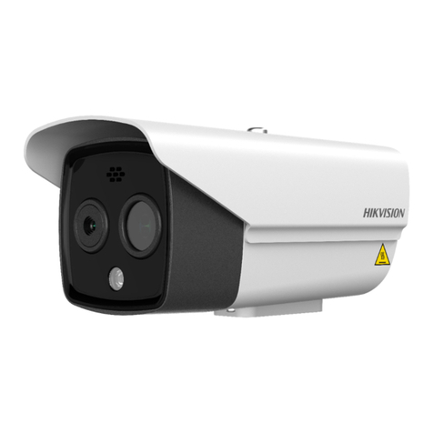
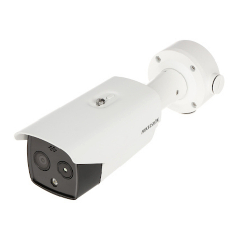
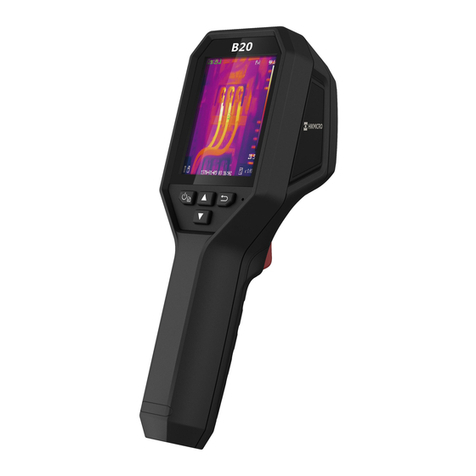
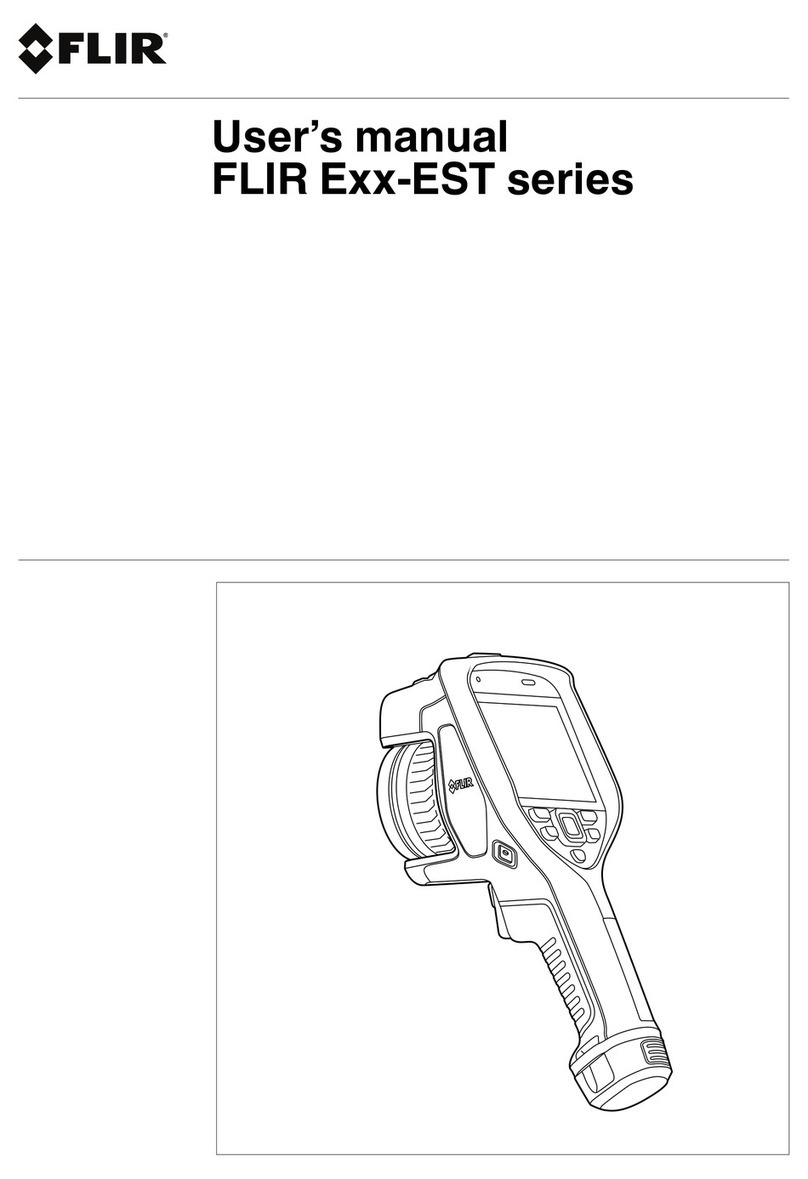
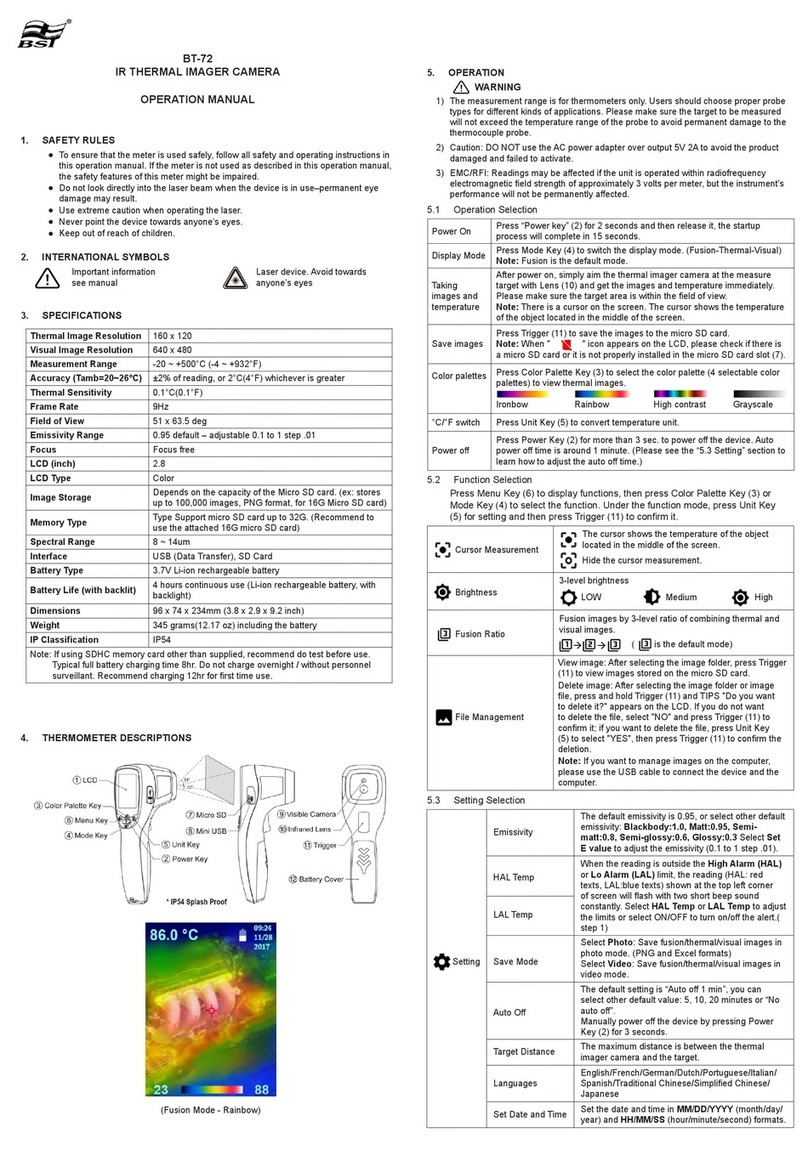
HIK VISION DS-2TD2137T-7/QY User manual

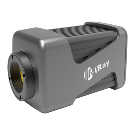
Thermal Network Camera
User Manual

Legal Informaon
©2023 Hangzhou Hikvision Digital Technology Co., Ltd. All rights reserved.
About this Manual
The Manual includes instrucons for using and managing the Product. Pictures, charts, images and
all other informaon hereinaer are for descripon and explanaon only. The informaon
contained in the Manual is subject to change, without noce, due to rmware updates or other
reasons. Please nd the latest version of this Manual at the Hikvision website ( hps://
www.hikvision.com/ ).
Please use this Manual with the guidance and assistance of professionals trained in supporng the
Product.
Trademarks
and other Hikvision's trademarks and logos are the properes of
Hikvision in various jurisdicons.
Other trademarks and logos menoned are the properes of their respecve owners.
Disclaimer
TO THE MAXIMUM EXTENT PERMITTED BY APPLICABLE LAW, THIS MANUAL AND THE PRODUCT
DESCRIBED, WITH ITS HARDWARE, SOFTWARE AND FIRMWARE, ARE PROVIDED "AS IS" AND "WITH
ALL FAULTS AND ERRORS". HIKVISION MAKES NO WARRANTIES, EXPRESS OR IMPLIED, INCLUDING
WITHOUT LIMITATION, MERCHANTABILITY, SATISFACTORY QUALITY, OR FITNESS FOR A PARTICULAR
PURPOSE. THE USE OF THE PRODUCT BY YOU IS AT YOUR OWN RISK. IN NO EVENT WILL HIKVISION
BE LIABLE TO YOU FOR ANY SPECIAL, CONSEQUENTIAL, INCIDENTAL, OR INDIRECT DAMAGES,
INCLUDING, AMONG OTHERS, DAMAGES FOR LOSS OF BUSINESS PROFITS, BUSINESS
INTERRUPTION, OR LOSS OF DATA, CORRUPTION OF SYSTEMS, OR LOSS OF DOCUMENTATION,
WHETHER BASED ON BREACH OF CONTRACT, TORT (INCLUDING NEGLIGENCE), PRODUCT LIABILITY,
OR OTHERWISE, IN CONNECTION WITH THE USE OF THE PRODUCT, EVEN IF HIKVISION HAS BEEN
ADVISED OF THE POSSIBILITY OF SUCH DAMAGES OR LOSS.
YOU ACKNOWLEDGE THAT THE NATURE OF THE INTERNET PROVIDES FOR INHERENT SECURITY
RISKS, AND HIKVISION SHALL NOT TAKE ANY RESPONSIBILITIES FOR ABNORMAL OPERATION,
PRIVACY LEAKAGE OR OTHER DAMAGES RESULTING FROM CYBER-ATTACK, HACKER ATTACK, VIRUS
INFECTION, OR OTHER INTERNET SECURITY RISKS; HOWEVER, HIKVISION WILL PROVIDE TIMELY
TECHNICAL SUPPORT IF REQUIRED.
YOU AGREE TO USE THIS PRODUCT IN COMPLIANCE WITH ALL APPLICABLE LAWS, AND YOU ARE
SOLELY RESPONSIBLE FOR ENSURING THAT YOUR USE CONFORMS TO THE APPLICABLE LAW.
ESPECIALLY, YOU ARE RESPONSIBLE, FOR USING THIS PRODUCT IN A MANNER THAT DOES NOT
INFRINGE ON THE RIGHTS OF THIRD PARTIES, INCLUDING WITHOUT LIMITATION, RIGHTS OF
PUBLICITY, INTELLECTUAL PROPERTY RIGHTS, OR DATA PROTECTION AND OTHER PRIVACY RIGHTS.
YOU SHALL NOT USE THIS PRODUCT FOR ANY PROHIBITED END-USES, INCLUDING THE
Thermal Network Camera User Manual
i

DEVELOPMENT OR PRODUCTION OF WEAPONS OF MASS DESTRUCTION, THE DEVELOPMENT OR
PRODUCTION OF CHEMICAL OR BIOLOGICAL WEAPONS, ANY ACTIVITIES IN THE CONTEXT RELATED
TO ANY NUCLEAR EXPLOSIVE OR UNSAFE NUCLEAR FUEL-CYCLE, OR IN SUPPORT OF HUMAN
RIGHTS ABUSES.
IN THE EVENT OF ANY CONFLICTS BETWEEN THIS MANUAL AND THE APPLICABLE LAW, THE LATTER
PREVAILS.
Thermal Network Camera User Manual
ii

Symbol Convenons
The symbols that may be found in this document are dened as follows.
Symbol Descripon
Danger
Indicates a hazardous situaon which, if not avoided, will or could
result in death or serious injury.
Cauon
Indicates a potenally hazardous situaon which, if not avoided, could
result in equipment damage, data loss, performance degradaon, or
unexpected results.
Note Provides addional informaon to emphasize or supplement
important points of the main text.
Thermal Network Camera User Manual
iii

Safety Instrucon
These instrucons are intended to ensure that user can use the product correctly to avoid danger
or property loss.
Laws and Regulaons
●In the use of the product, you must be in strict compliance with the electrical safety regulaons
of the naon and region.
Transportaon
●Keep the device in original or similar packaging while transporng it.
●Keep all wrappers aer unpacking them for future use. In case of any failure occurred, you need
to return the device to the factory with the original wrapper. Transportaon without the original
wrapper may result in damage on the device and the company shall not take any responsibilies.
●DO NOT drop the product or subject it to physical shock. Keep the device away from magnec
interference.
Power Supply
●Check the input voltage before powering on the device to avoid damage.
●CAUTION: If the fuse of the device can be replaced, replace it only with the same model to
reduce the risk of re or electric shock.
●If a fuse is connected to the neutral wire and a double pole/neutral fusing occurs, parts of the
device that remain energized might represent a hazard during servicing aer operaon of the
fuse.
●If the device uses a 3-prong power supply plug, it must be connected to an earthed mains
socket-outlet properly.
●Do not touch the bare components (such as the metal contacts of the inlets) and wait for at least
5 minutes, since electricity may sll exist aer the device is powered o.
●For the permanently connected device without a disconnect equipment, a readily accessible
disconnect equipment shall be incorporated into the electrical installaon of the connected
building.
●For the permanently connected device without an overcurrent protecon equipment, an
overcurrent protecon equipment shall be incorporated into the electrical installaon of the
connected building. The specicaons of the overcurrent protecon equipment shall not exceed
that of the building.
●For the permanently connected device without an all-pole mains switch, an all-pole mains switch
shall be incorporated into the electrical installaon of the connected building.
●If the device is powered by terminals connected to the power cord, ensure correct voltage and
wiring of the terminals for connecon to mains supply.
Thermal Network Camera User Manual
iv

●Please purchase the charger by yourself. Input voltage should meet the Limited Power Source
(12 VDC, 24 VAC, or PoE(802.3af)) according to the IEC62368 standard. Please refer to technical
specicaons for detailed informaon.
●Make sure the plug is properly connected to the power socket.
●The socket-outlet shall be installed near the equipment and shall be easily accessible.
●DO NOT connect mulple devices to one power adapter, to avoid over-heang or re hazards
caused by overload.
●DO NOT touch the bare metal contacts of the inlets aer the circuit breaker is turned o.
Electricity sll exists.
●+ idenes the posive terminal(s) of equipment which is used with, or generates direct current.
- idenes the negave terminal(s) of equipment which is used with, or generates direct current.
Baery
●Risk of explosion if the baery is replaced by an incorrect type. Dispose of used baeries
according to the instrucons.
●The built-in baery cannot be dismantled. Please contact the manufacture for repair if
necessary.
●For long-term storage of the baery, make sure it is fully charged every half year to ensure the
baery quality. Otherwise, damage may occur.
●This equipment is not suitable for use in locaons where children are likely to be present.
●Improper replacement of the baery with an incorrect type may defeat a safeguard (for
example, in the case of some lithium baery types).
●DO NOT dispose of the baery into re or a hot oven, or mechanically crush or cut the baery,
which may result in an explosion.
●DO NOT leave the baery in an extremely high temperature surrounding environment, which
may result in an explosion or the leakage of ammable liquid or gas.
●DO NOT subject the baery to extremely low air pressure, which may result in an explosion or
the leakage of ammable liquid or gas.
Installaon
●This device is suitable for use above 2 m only.
●Install the device according to the instrucons in Quick Start Guide. To prevent injury, this device
must be securely aached to the installaon surface in accordance with the installaon
instrucons.
●Never place the device in an unstable locaon. The device may fall, causing serious personal
injury or death.
●The addional force shall be equal to three mes the weight of the device but not less than 50
N. The device and its associated mounng means shall remain secure during the installaon.
Aer the installaon, the device, including any associated mounng plate, shall not be damaged.
●Never place the equipment in an unstable locaon. The equipment may fall, causing serious
personal injury or death.
●This equipment is for use only with corresponding brackets. Use with other (carts, stands, or
carriers) may result in instability causing injury.
Thermal Network Camera User Manual
v

●The interface varies with the models. Please refer to the product datasheet for details.
●If the device needs to be wired by yourself, select the corresponding wire to supply power
according to the electric parameters labeled on the device. Strip o wire with a standard wire
stripper at corresponding posion. To avoid serious consequences, the length of stripped wire
shall be appropriate, and conductors shall not be exposed.
●Make sure that the power has been disconnected before you wire, install, or disassemble the
device.
System Security
●You acknowledge that the nature of Internet provides for inherent security risks, and our
company shall not take any responsibilies for abnormal operaon, privacy leakage or other
damages resulng from cyber aack, hacker aack, however, our company will provide mely
technical support if required.
●Please enforce the protecon for the personal informaon and the data security as the device
may be confronted with the network security problems when it is connected to the Internet.
Please contact us when the device might exist network security risks.
●Please understand that you have the responsibility to congure all the passwords and other
security sengs about the device, and keep your user name and password.
Maintenance
●If the product does not work properly, please contact your dealer or the nearest service center.
We shall not assume any responsibility for problems caused by unauthorized repair or
maintenance.
●A few device components (e.g., electrolyc capacitor) require regular replacement. The average
lifespan varies, so periodic checking is recommended. Contact your dealer for details.
●Wipe the device gently with a clean cloth and a small quanty of ethanol, if necessary.
●If the equipment is used in a manner not specied by the manufacturer, the protecon provided
by the device may be impaired.
●To reduce the risk of re, replace only with the same type and rang of fuse.
●The serial port of the equipment is used for debugging only.
Using Environment
●Make sure the running environment meets the requirement of the device. The operang
temperature shall be -40°C to 65°C (-40°F to 149°F), and the operang humidity shall be 95% or
less, no condensing.
●DO NOT expose the device to high electromagnec radiaon or dusty environments.
●DO NOT aim the lens at the sun or any other bright light.
●The equipment shall not be exposed to dripping or splashing and that no objects lled with
liquids, such as vases, shall be placed on the equipment.
●No naked ame sources, such as lighted candles, should be placed on the equipment.
●For the device with venlaon openings, the venlaon openings should not be impeded by
covering the venlaon openings with items, such as newspapers, table-cloths, and curtains.
Thermal Network Camera User Manual
vi

The openings shall never be blocked by placing the device on a bed, sofa, rug, or other similar
surface.
●Keep a proper distance around the device for sucient venlaon.
●This device is suitable for mounng on concrete or other non-combusble surface only to avoid
re hazard.
●This equipment is not suitable for use in locaons where children are likely to be present.
●Provide a surge suppressor at the inlet opening of the equipment under special condions such
as the mountain top, iron tower, and forest.
●Burned ngers when handling the parts with symbol . Wait one-half hour aer switching o
before handling the parts.
Emergency
●If smoke, odor, or noise arises from the device, immediately turn o the power, unplug the
power cable, and contact the service center.
COMPLIANCE NOTICE: The thermal series products might be subject to export controls in various
countries or regions, including without limitaon, the United States, European Union, United
Kingdom and/or other member countries of the Wassenaar Arrangement. Please consult your
professional legal or compliance expert or local government authories for any necessary export
license requirements if you intend to transfer, export, re-export the thermal series products
between dierent countries.
Thermal Network Camera User Manual
vii

Contents
Chapter 1 Overview .................................................................................................................... 1
1.1 Brief Descripon .................................................................................................................... 1
1.2 Funcon ................................................................................................................................. 1
Chapter 2 Device Acvaon and Accessing ................................................................................. 2
2.1 Acvate Device ...................................................................................................................... 2
2.1.1 Acvate the Device via Browser .................................................................................... 2
2.1.2 Acvate the Device via SADP ........................................................................................ 3
2.2 Login ...................................................................................................................................... 3
2.2.1 Plug-in Installaon ........................................................................................................ 3
2.2.2 Illegal Login Lock ........................................................................................................... 4
Chapter 3 Network Sengs ........................................................................................................ 5
3.1 TCP/IP ..................................................................................................................................... 5
3.1.1 Mulcast Discovery ....................................................................................................... 6
3.2 Port ........................................................................................................................................ 6
3.3 Port Mapping ......................................................................................................................... 7
3.3.1 Set Auto Port Mapping .................................................................................................. 7
3.3.2 Set Manual Port Mapping ............................................................................................. 8
3.4 Mulcast ................................................................................................................................ 8
3.5 SNMP ..................................................................................................................................... 8
3.6 Access to Device via Domain Name ....................................................................................... 9
3.7 Access to Device via PPPoE Dial Up Connecon .................................................................. 10
3.8 Set ISUP ................................................................................................................................ 10
3.9 Set Open Network Video Interface ...................................................................................... 11
3.10 Set Alarm Host ................................................................................................................... 11
3.11 Set Alarm Server ................................................................................................................ 11
3.12 Set Network Service ........................................................................................................... 12
Thermal Network Camera User Manual
viii

3.13 Set SRTP ............................................................................................................................. 12
3.14 Set Modbus ........................................................................................................................ 13
3.15 Operate via Mobile Client .................................................................................................. 13
3.15.1 Enable Hik-Connect Service on Camera .................................................................... 14
3.15.2 Set Up Hik-Connect ................................................................................................... 15
3.15.3 Add Camera to Hik-Connect ...................................................................................... 15
Chapter 4 Live View .................................................................................................................. 17
4.1 Live View Parameters ........................................................................................................... 17
4.1.1 Window Division ......................................................................................................... 17
4.1.2 Live View Stream Type ................................................................................................ 17
4.1.3 Enable and Disable Live View ...................................................................................... 17
4.1.4 Start Digital Zoom ....................................................................................................... 17
4.1.5 View Previous/Next Page ............................................................................................ 18
4.1.6 Full Screen ................................................................................................................... 18
4.1.7 Light ............................................................................................................................ 18
4.1.8 Wiper .......................................................................................................................... 18
4.1.9 Lens Inializaon ........................................................................................................ 18
4.1.10 Auxiliary Focus .......................................................................................................... 18
4.1.11 Quick Set Live View ................................................................................................... 18
4.1.12 Lens Parameters Adjustment .................................................................................... 19
4.2 Set Transmission Parameters ............................................................................................... 19
Chapter 5 Video and Image Sengs ......................................................................................... 21
5.1 Video Sengs ...................................................................................................................... 21
5.1.1 Stream Type ................................................................................................................ 21
5.1.2 Video Type .................................................................................................................. 21
5.1.3 Resoluon ................................................................................................................... 21
5.1.4 Bitrate Type and Max. Bitrate ..................................................................................... 22
5.1.5 Video Quality .............................................................................................................. 22
Thermal Network Camera User Manual
ix

5.1.6 Frame Rate .................................................................................................................. 22
5.1.7 Video Encoding ........................................................................................................... 22
5.1.8 Smoothing ................................................................................................................... 24
5.1.9 Display VCA Info .......................................................................................................... 24
5.1.10 Audio Sengs ........................................................................................................... 24
5.1.11 Two-way Audio .......................................................................................................... 25
5.1.12 Set ROI ...................................................................................................................... 25
5.1.13 Metadata .................................................................................................................. 26
5.2 Display Sengs .................................................................................................................... 26
5.2.1 Image Adjustment ....................................................................................................... 26
5.2.2 Image Adjustment (Thermal Channel) ........................................................................ 26
5.2.3 DNR ............................................................................................................................. 27
5.2.4 Set Palee ................................................................................................................... 27
5.2.5 Set Target Enhancement ............................................................................................. 28
5.2.6 DDE ............................................................................................................................. 28
5.2.7 Brightness Sudden Change ......................................................................................... 28
5.2.8 Enhance Regional Image ............................................................................................. 29
5.2.9 Mirror .......................................................................................................................... 29
5.2.10 Video Standard ......................................................................................................... 29
5.2.11 Digital Zoom .............................................................................................................. 29
5.2.12 Scene Mode .............................................................................................................. 29
5.2.13 Local Output .............................................................................................................. 29
5.3 OSD ...................................................................................................................................... 30
5.4 VCA Rule Display Sengs .................................................................................................... 30
5.5 Set Privacy Mask .................................................................................................................. 30
5.6 Overlay Picture ..................................................................................................................... 31
5.7 Set Manual DPC (Defecve Pixel Correcon) ....................................................................... 31
Chapter 6 Video Recording and Picture Capture ........................................................................ 32
Thermal Network Camera User Manual
x

6.1 Storage Sengs ................................................................................................................... 32
6.1.1 Set Memory Card ........................................................................................................ 32
6.1.2 Set NAS ....................................................................................................................... 32
6.1.3 Set FTP ........................................................................................................................ 33
6.1.4 Set Cloud Storage ........................................................................................................ 34
6.2 Video Recording ................................................................................................................... 34
6.2.1 Record Automacally .................................................................................................. 34
6.2.2 Record Manually ......................................................................................................... 36
6.2.3 Playback and Download Video .................................................................................... 36
6.3 Capture Conguraon .......................................................................................................... 37
6.3.1 Capture Automacally ................................................................................................ 37
6.3.2 Capture Manually ........................................................................................................ 37
6.3.3 View and Download Picture ........................................................................................ 38
Chapter 7 VCA Resource ........................................................................................................... 39
7.1 Temperature Measurement ................................................................................................. 39
7.1.1 Noce .......................................................................................................................... 39
7.1.2 Thermography Conguraon Flow Chart .................................................................... 39
7.1.3 Automac Thermography ........................................................................................... 41
7.1.4 Manual Thermography ............................................................................................... 48
7.2 Fire Detecon ...................................................................................................................... 48
7.2.1 Recommended Scene ................................................................................................. 49
7.2.2 Set Dynamic Fire Source Detecon ............................................................................. 49
7.2.3 Set Detecon Shield Region ........................................................................................ 50
7.3 Perimeter Protecon ........................................................................................................... 50
7.3.1 Set Perimeter Protecon Rules ................................................................................... 50
7.3.2 Set Perimeter Protecon Shield Region ...................................................................... 53
7.3.3 Set Overlay & Capture Parameters ............................................................................. 53
7.3.4 Calibraon ................................................................................................................... 54
Thermal Network Camera User Manual
xi

7.3.5 Set Advanced Conguraon Parameters .................................................................... 56
7.4 Open Plaorm ...................................................................................................................... 56
7.4.1 Set Open Plaorm ....................................................................................................... 56
Chapter 8 Event and Alarm ....................................................................................................... 58
8.1 Set Moon Detecon ........................................................................................................... 58
8.1.1 Normal Mode .............................................................................................................. 58
8.1.2 Expert Mode ............................................................................................................... 59
8.2 Set Video Tampering Alarm ................................................................................................. 59
8.3 Set Alarm Input .................................................................................................................... 60
8.4 Set Excepon Alarm ............................................................................................................. 61
8.5 Detect Audio Excepon ........................................................................................................ 61
8.6 Detect Scene Change ........................................................................................................... 62
Chapter 9 Arming Schedule and Alarm Linkage ......................................................................... 63
9.1 Set Arming Schedule ............................................................................................................ 63
9.2 Linkage Method Sengs ...................................................................................................... 63
9.2.1 Trigger Alarm Output .................................................................................................. 63
9.2.2 FTP/NAS/Memory Card Uploading ............................................................................. 65
9.2.3 Send Email .................................................................................................................. 65
9.2.4 Nofy Surveillance Center .......................................................................................... 66
9.2.5 Trigger Recording ........................................................................................................ 66
9.2.6 Set Audible Alarm Output ........................................................................................... 67
9.2.7 Set Flashing Alarm Light Output ................................................................................. 67
Chapter 10 System and Security ................................................................................................ 68
10.1 View Device Informaon .................................................................................................... 68
10.2 Search and Manage Log ..................................................................................................... 68
10.3 Import and Export Conguraon File ................................................................................ 68
10.4 Export Diagnose Informaon ............................................................................................. 69
10.5 Reboot ............................................................................................................................... 69
Thermal Network Camera User Manual
xii

10.6 Device Auto Maintenance .................................................................................................. 69
10.7 Restore and Default ........................................................................................................... 69
10.8 Upgrade ............................................................................................................................. 70
10.9 View Open Source Soware License .................................................................................. 70
10.10 Time and Date .................................................................................................................. 70
10.10.1 Synchronize Time Manually .................................................................................... 70
10.10.2 Set NTP Server ........................................................................................................ 71
10.10.3 Set DST .................................................................................................................... 71
10.11 Set RS-232 ........................................................................................................................ 71
10.12 Set RS-485 ........................................................................................................................ 72
10.13 Set Same Unit .................................................................................................................. 72
10.14 Security ............................................................................................................................ 72
10.14.1 Authencaon ........................................................................................................ 73
10.14.2 Security Audit Log ................................................................................................... 73
10.14.3 Set IP Address Filter ................................................................................................ 74
10.14.4 Set MAC Address Filter ........................................................................................... 74
10.14.5 Cercate Management ......................................................................................... 75
10.14.6 Control Timeout Sengs ........................................................................................ 77
10.14.7 Set SSH .................................................................................................................... 77
10.14.8 Set HTTPS ................................................................................................................ 77
10.14.9 Set QoS .................................................................................................................... 78
10.14.10 Set IEEE 802.1X ..................................................................................................... 78
10.15 User and Account ............................................................................................................. 79
10.15.1 Set User Account and Permission ........................................................................... 79
10.15.2 Online Users ............................................................................................................ 80
Chapter 11 Appendix ................................................................................................................ 81
11.1 Common Material Emissivity Reference ............................................................................ 81
11.2 FAQ ..................................................................................................................................... 81
Thermal Network Camera User Manual
xiii

Chapter 1 Overview
1.1 Brief Descripon
Thermal network camera equipped with built-in GPU which supports intelligent perimeter
protecon algorithm, can realize high-precision VCA detecon and real-me alarm. It is applied to
perimeter protecon and re-prevenon purposes in crical infrastructures such as community,
villa, construcon site, factory, 4S stores, and so on. The pre-alarm system helps you discover
unexpected events immediately and protects your property.
1.2 Funcon
This secon introduces main funcons of the device.
Note
Not all models support the conguraons below. Take the actual product for reference.
Fire Detecon
Device can detect the dynamic re source in the scene and output pre-alarm and alarm to protect
the property.
Temperature Measurement
Device can measure the actual temperature of the spot being monitored. The device alarms when
temperature exceeds the temperature threshold value.
Perimeter Protecon
Device can do perimeter protecon. Mulple rules can be congured for dierent requirements.
Open Plaorm
Device supports the installaon of applicaon for the third-party to develop and run its funcon
and service.
Thermal Network Camera User Manual
1

Chapter 2 Device Acvaon and Accessing
To protect the security and privacy of the user account and data, you should set a login password
to acvate the device when access the device via network.
Note
Refer to the user manual of the soware client for the detailed informaon about the client
soware acvaon.
2.1 Acvate Device
The device needs to be acvated by seng a strong password before use. This part introduces
acvaon using dierent client tools.
2.1.1 Acvate the Device via Browser
You can access and acvate the device via the browser.
Steps
1. Connect your computer to the same Wi-Fi network that the device is in.
2. Change the IP address of the computer and device to the same segment.
Note
The default IP address of the device is 192.168.1.64. You can set the IP address of the computer
from 192.168.1.2 to 192.168.1.253 (except 192.168.1.64). For example, you can set the IP
address of the PC to 192.168.1.100.
3. Input 192.168.1.64 in the browser.
4. Set device acvaon password.
Cauon
We highly recommend you create a strong password of your own choosing (using a minimum of
8 characters, including at least three of the following categories: upper case leers, lower case
leers, numbers, and special characters) in order to increase the security of your product. And
we recommend you reset your password regularly, especially in the high security system,
reseng the password monthly or weekly can beer protect your product.
5. Click OK.
6. Input the acvaon password to log in to the device.
7. Oponal: Go to Conguraon → Network → Basic → TCP/IP to change the IP address of the
device to the same segment of your network.
Thermal Network Camera User Manual
2

2.1.2 Acvate the Device via SADP
Search and acvate the online devices via SADP soware.
Before You Start
Access www.hikvision.com to get SADP soware to install.
Steps
1. Connect your computer to the same Wi-Fi network that the device is in.
2. Run SADP soware to search the online devices of the LAN.
3. Check Device Status from the device list, and select Inacve device.
4. Create and input the new password in the password eld, and conrm the password.
Cauon
We highly recommend you create a strong password of your own choosing (using a minimum of
8 characters, including upper case leers, lower case leers, numbers, and special characters) in
order to increase the security of your product. And we recommend you reset your password
regularly, especially in the high security system, reseng the password monthly or weekly can
beer protect your product.
5. Click OK.
Device Status changes into Acve.
6. Oponal: Change the network parameters of the device in Modify Network Parameters.
2.2 Login
Log in to the device via Web browser.
2.2.1 Plug-in Installaon
Certain operaon systems and web browser may restrict the display and operaon of the device
funcon. You should install plug-in or complete certain sengs to ensure normal display and
operaon. For detailed restricted funcon, refer to the actual device.
Operang System Web Browser Operaon
Windows Internet Explorer 10+ Follow pop-up prompts to
complete plug-in installaon.
Google Chrome 57+
Mozilla Firefox 52+
Microso Edge 79.0.309+
Click to
download and install plug-in.
Go to Conguraon →
Network → Advanced Sengs
Thermal Network Camera User Manual
3

Operang System Web Browser Operaon
→ Network Service to enable
WebSocket or WebSockets for
normal view if plug-in
installaon is not required.
Display and operaon of
certain funcons are restricted.
For example, Playback and
Picture are not available. For
detailed restricted funcon,
refer to the actual device.
Mac OS 10.13+ Mac Safari 12+ Plug-in installaon is not
required.
Go to Conguraon →
Network → Advanced Sengs
→ Network Service to enable
WebSocket or WebSockets for
normal view. Display and
operaon of certain funcons
are restricted. For example,
Playback and Picture are not
available. For detailed
restricted funcon, refer to the
actual device.
Note
The device only supports Windows and Mac OS system and does not support Linux system.
2.2.2 Illegal Login Lock
It helps to improve the security when accessing the device via Internet.
Go to Conguraon → System → Security → Security Service , and enable Enable Illegal Login
Lock, Illegal Login Aempts and Locking Duraon are congurable.
Illegal Login Aempts
When your login aempts with the wrong password reach the set mes, the device is locked.
Locking Duraon
The device releases the lock aer the seng duraon.
Thermal Network Camera User Manual
4

Chapter 3 Network Sengs
3.1 TCP/IP
TCP/IP sengs must be properly congured before you operate the device over network. IPv4 and
IPv6 are both supported. Both versions can be congured simultaneously without conicng to
each other.
Go to Conguraon → Basic Conguraon → Network → TCP/IP for parameter sengs.
NIC Type
Select a NIC (Network Interface Card) type according to your network condion.
IPv4
Two IPv4 modes are available.
DHCP
The device automacally gets the IPv4 parameters from the network if you check DHCP. The
device IP address is changed aer enabling the funcon. You can use SADP to get the device IP
address.
Note
The network that the device is connected to should support DHCP (Dynamic Host
Conguraon Protocol).
Manual
You can set the device IPv4 parameters manually. Input IPv4 Address, IPv4 Subnet Mask, and
IPv4 Default Gateway, and click Test to see if the IP address is available.
IPv6
Three IPv6 modes are available.
Route Adversement
The IPv6 address is generated by combining the route adversement and the device Mac
address.
Note
Route adversement mode requires the support from the router that the device is connected
to.
DHCP
The IPv6 address is assigned by the server, router or gateway.
Manual
Thermal Network Camera User Manual
5

Input IPv6 Address, IPv6 Subnet, IPv6 Default Gateway. Consult the network administrator for
required informaon.
MTU
It stands for maximum transmission unit. It is the size of the largest protocol data unit that can
be communicated in a single network layer transacon.
The valid value range of MTU is 1280 to 1500.
DNS
It stands for domain name server. It is required if you need to visit the device with domain
name. And it is also required for some applicaons (e.g., sending email). Set Preferred DNS
Server and Alternate DNS server properly if needed.
3.1.1 Mulcast Discovery
Check the Enable Mulcast Discovery, and then the online network camera can be automacally
detected by client soware via private mulcast protocol in the LAN.
3.2 Port
The device port can be modied when the device cannot access the network due to port conicts.
Cauon
Do not modify the default port parameters at will, otherwise the device may be inaccessible.
Go to Conguraon → Network → Basic Sengs → Port for port sengs.
HTTP Port
It refers to the port through which the browser accesses the device. For example, when the
HTTP Port is modied to 81, you need to enter hp://192.168.1.64:81 in the browser for login.
HTTPS Port
It refers to the port through which the browser accesses the device with cercate. Cercate
vericaon is required to ensure the secure access.
RTSP Port
It refers to the port of real-me streaming protocol.
SRTP Port
It refers to the port of secure real-me transport protocol.
Server Port
It refers to the port through which the client adds the device.
WebSocket Port
Thermal Network Camera User Manual
6
This manual suits for next models
20
Table of contents
Other HIK VISION Thermal Camera manuals

HIK VISION
HIK VISION DS-2TD4035D-25(50) User manual

HIK VISION
HIK VISION DS-2TP21B-6AVFW User manual

HIK VISION
HIK VISION DS-2TD25 Series User manual

HIK VISION
HIK VISION DS-2TP31B-3AUF User manual

HIK VISION
HIK VISION Thermal Driving Assistance System User manual

HIK VISION
HIK VISION DS-2TD2617-6/PA User manual

HIK VISION
HIK VISION DS-2TD5537T-7/W User manual

HIK VISION
HIK VISION DS-2TP31-3AUF User manual

HIK VISION
HIK VISION DS-2TD2537T-4/Q User manual

HIK VISION
HIK VISION Performance Series User manual