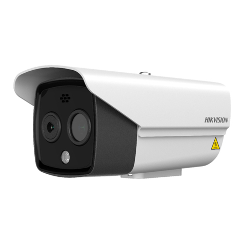
HIK VISION Performance Series User manual

Performance Series Thermal
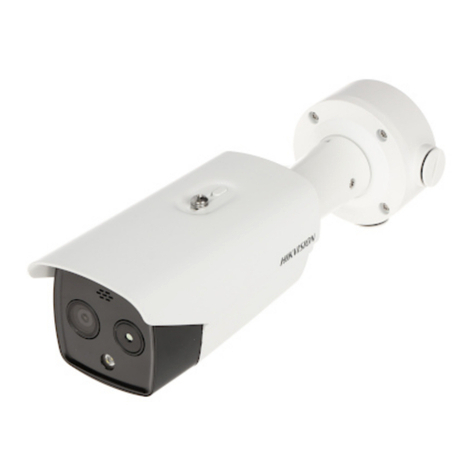
2CD-TDxx17-x/V1
Thermal Camera
Configuration Guide

Performance Series Thermal Camera Configuration Guide
CG PS Thermal Cameras 072619NA 2
Copyright
2019 Hikvision USA Inc. and Hikvision Canada Inc.
Hikvision USA Inc.,
18639 Rai road St., City of Industry, CA 91748, USA
Hikvision Canada,
4848 rue Levy, Saint Laurent, Quebec, Canada, H4R 2P1
Te ephone: +1-909-895-0400 • To Free in USA: +1-866-200-6690
E-Mai : sa es.usa@hikvision.com • www.hikvision.com
ALL RIGHTS RESERVED.
Any and a information, inc uding, among others, wordings, pictures, graphs are the properties of Hangzhou Hikvision Digita Techno ogy Co., Ltd. or its
subsidiaries (hereinafter referred to be “Hikvision”). This user manua (hereinafter referred to be “the Manua ”) cannot be reproduced, changed, trans ated, or
distributed, partia y or who y, by any means, without the prior written permission of Hikvision. Un ess otherwise stipu ated, Hikvision does not make any
warranties, guarantees or representations, express or imp ied, regarding to the Manua .
About this Manual
The Manua inc udes instructions for using and managing the product. Pictures, charts, images and a other information hereinafter are for description and
exp anation on y. The information contained in the Manua is subject to change, without notice, due to firmware updates or other reasons. P ease find the
atest version in the company Website (http://overseas.hikvision.com/en/).
P ease use this user manua under the guidance of professiona s.
Manual Illust ations and Featu es
Graphics (screen shots, product pictures, etc.) in this document are for i ustrative purposes on y. Your actua product may differ in appearance. Your product
might not support a features discussed in this document.
T adema ks Acknowledgement
and other Hikvision trademarks and ogos are the properties of Hikvision in various jurisdictions. Other trademarks and ogos mentioned be ow
are the properties of their respective owners.
Legal Disclaime
TO THE MAXIMUM EXTENT PERMITTED BY APPLICABLE LAW, THE PRODUCT DESCRIBED, WITH ITS HARDWARE, SOFTWARE AND FIRMWARE, IS
PROVIDED “AS IS,” WITH ALL FAULTS AND ERRORS, AND HIKVISION MAKES NO WARRANTIES, EXPRESS OR IMPLIED, INCLUDING WITHOUT
LIMITATION, MERCHANTABILITY, SATISFACTORY QUALITY, FITNESS FOR A PARTICULAR PURPOSE, AND NON-INFRINGEMENT OF THIRD PARTY. IN
NO EVENT WILL HIKVISION, ITS DIRECTORS, OFFICERS, EMPLOYEES, OR AGENTS BE LIABLE TO YOU FOR ANY SPECIAL, CONSEQUENTIAL,
INCIDENTAL, OR INDIRECT DAMAGES, INCLUDING, AMONG OTHERS, DAMAGES FOR LOSS OF BUSINESS PROFITS, BUSINESS INTERRUPTION, OR
LOSS OF DATA OR DOCUMENTATION, IN CONNECTION WITH THE USE OF THIS PRODUCT, EVEN IF HIKVISION HAS BEEN ADVISED OF THE
POSSIBILITY OF SUCH DAMAGES.
REGARDING TO THE PRODUCT WITH INTERNET ACCESS, THE USE OF PRODUCT SHALL BE WHOLLY AT YOUR OWN RISKS. HIKVISION SHALL NOT
TAKE ANY RESPONSIBILITIES FOR ABNORMAL OPERATION, PRIVACY LEAKAGE OR OTHER DAMAGES RESULTING FROM CYBER ATTACK, HACKER
ATTACK, VIRUS INSPECTION, OR OTHER INTERNET SECURITY RISKS; HOWEVER, HIKVISION WILL PROVIDE TIMELY TECHNICAL SUPPORT IF
REQUIRED.
SURVEILLANCE LAWS VARY BY JURISDICTION. PLEASE CHECK ALL RELEVANT LAWS IN YOUR JURISDICTION BEFORE USING THIS PRODUCT IN
ORDER TO ENSURE THAT YOUR USE CONFORMS TO THE APPLICABLE LAW. HIKVISION SHALL NOT BE LIABLE IN THE EVENT THAT THIS
PRODUCT IS USED FOR ILLEGITIMATE PURPOSES.
IN THE EVENT OF ANY CONFLICTS BETWEEN THIS MANUAL AND THE APPLICABLE LAW, THE LATTER PREVAILS.
Regulato y Info mation
FCC Info mation
P ease take attention that changes or modification not express y approved by the party responsib e for comp iance cou d void the user’s authority to operate
the equipment.
FCC Compliance:
This equipment has been tested and found to comp y with the imits for a C ass A digita device, pursuant to part 15 of the FCC Ru es.
These imits are designed to provide reasonab e protection against harmfu interference when the equipment is operated in a commercia environment. This
equipment generates, uses, and can radiate radio frequency energy and, if not insta ed and used in accordance with the instruction manua , may cause
harmfu interference to radio communications. Operation of this equipment in a residentia area is ike y to cause harmfu interference in which case the user
wi be required to correct the interference at his own expense.
FCC Conditions
This device comp ies with part 15 of the FCC Ru es. Operation is subject to the fo owing two conditions:
•
This device may not cause harmfu interference.
•
This device must accept any interference received, inc uding interference that may cause undesired operation.
EU Confo mity Statement
This product and, if app icab e, the supp ied accessories too are marked with “CE” and comp y therefore with the app icab e harmonized European
standards isted under the EMC Directive 2014/30/EU, the LVD Directive 2014/35/EU, the RoHS Directive 2011/65/EU.
2012/19/EU (WEEE Di ective):
Products marked with this symbo cannot be disposed of as unsorted municipa waste in the European Union. For
proper recyc ing, return this product to your oca supp ier upon the purchase of equiva ent new equipment, or dispose of it at designated co ection
points. For more information see: www.recyc ethis.info
2006/66/EC (Batte y Di ective):
This product contains a battery that cannot be disposed of as unsorted municipa waste in the European Union. See
the product documentation for specific battery information. The battery is marked with this symbo , which may inc ude ettering to indicate cadmium
(Cd), ead (Pb), or mercury (Hg). For proper recyc ing, return the battery to your supp ier or to a designated co ection point. For more information see:
www.recyc ethis.info
Indust y Canada ICES-003 Compliance
This device meets the CAN ICES-3 (A)/NMB-3(A) standards requirements.
Performance Series Thermal Camera Configuration Guide
CG PS Thermal Cameras 072619NA 3
Table of Contents
Table of ContentsTable of Contents
Table of Contents
Introduction .................................................................................................................................................... 4
VCA (Video Content Analysis) ..................................................................................................................... 4
Temperature Measurement ......................................................................................................................... 9
Fire Source Detection ................................................................................................................................. 14
Display VCA In o by Video .......................................................................................................................... 16
Image ............................................................................................................................................................. 16
Temperature Highlight ................................................................................................................................ 18

Performance Series Thermal Camera Configuration Guide
CG PS Thermal Cameras 072619NA
Introduction
This guide explains how to configure a Hikvision Performance Series thermal camera.
This configuration guide is for the following Hikvision Performance Series cameras:
•2CD TD1217 x/V1
•2CD TD2117 x/V1
•2CD TD2617 x/V1
VCA (Video Content Analysis)
1. Enter the cameraʼs IP address in a Web browser to access the cameraʼs interface.
2. Go to Con iguration > Maintenance > VCA Resource Type.
3. Check the Temperature Measurement + Behavior Analysis radio button (default).
4. Click the Save button.
Figure 1, VCA Resource Configuration
5. Go to Con iguration > Local to view the Live View parameters.
6. Check the Rules − Enable radio button.

Performance Series Thermal Camera Configuration Guide
CG PS Thermal Cameras 072619NA 5
Figure 2, Live View Parameters
7. Go to Con iguration > Basic Settings.
8. Check the Intelligent Analysis checkbox.
9. Click the Save button.
Figure 3, Display on Picture
10. Go to Con iguration > VCA > Rule.
11. Create one or more rules.
NOTE:
NOTE:NOTE:
NOTE: A Line Crossing rule will be used as an example here. Other VCA functions will have
different choices.
12. Click the button to define a rule.

Performance Series Thermal Camera Configuration Guide
CG PS Thermal Cameras 072619NA
6
Figure 4, Rule List
13. Configure the rule using the following as an example (actual choices will vary by VCA function).
•Enable: Click this checkbox to enable this rule.
•No. (Read Only): Displays the rule number.
•Rule Name: Input a escriptive name for this rule.
•Rule Type: Use the pull- own menu to select which VCA feature this rule is for.
•Delete Icon X: Click to elete this rule.
•Copy Icon : Click to make a copy of this rule.
•Filter by: Use the pull- own menu to select how to filter the target. To etect the target more
accurately, it is suggeste to use Filter by Pi el.
•Ma . Size (Read Only): The maximum target pixel size to etect.
•Min. Size (Read Only): The minimum pixel size to etect.
•Sensitivity: Enter the sensitivity to etermine how intrusive a breach has to be to trigger an alarm.
•Line Crossing: Use the pull- own menu to select the line crossing irection that will trigger an
alarm.
•Detection Target: Use the pull- own menu to select target type: Human, Vehicle, or Both.
•Background Interference: Use the pull- own menu to turn the Background Interference filter
ON or OFF. The Background Interference filter eliminates backgroun noise such as rustling
leaves.

Performance Series Thermal Camera Configuration Guide
CG PS Thermal Cameras 072619NA
7
Figure 5, Rule List Settings
14. Go to Live View to set the following:
•Ma imum Size Icon
:
::
: Click to rag an place a box to efine the maximum size target to
etect.
•Minimum Size Icon :
::
: Click to rag an place a box to efine the minimum size target to
etect.
•Line Icon :
::
: Click to rag an raw a line over which a target crosses to be etecte .
Figure 6, Setting Rules in Live View
15. Repeat Steps 12 an 13 to set a itional rules.

Performance Series Thermal Camera Configuration Guide
CG PS Thermal Cameras 072619NA 8
Figure , Rule Settings
Figure 8, Rule Settings Example
16. Verify the VCA effect rules in Live View.

Performance Series Thermal Camera Configuration Guide
CG PS Thermal Cameras 072619NA 9
Figure 9, Live View
Temperature Measurement
1. Go to Con iguration > Maintenance > VCA Resource Type.
2. Check the VCA Resource Con iguration: Temperature Measurement + Behavior Analysis radio
button.

Performance Series Thermal Camera Configuration Guide
CG PS Thermal Cameras 072619NA 10
Figure 10, VCA Resource Configuration
3. Go to Con iguration > Local.
4. Check the Live View Parameters: Display Temperature In o, Yes radio buttons.
Figure 11, Live View Parameters
5. Go to Con iguration > Temperature Measurement > Basic Settings.
6. Set the following items:
•Channel No.: Use the pull down menu to select the camera you want to configure.
•Enable Temperature Measurement: Check the checkbox.
•Display Min. Temperature: Check the checkbox.
•Display Average Temperature: Check the checkbox.

Performance Series Thermal Camera Configuration Guide
CG PS Thermal Cameras 072619NA
11
Figure 12Temperature Measurement, Basic Settings
7. Go to Configuration > Temperature Measurement > Advanced Settings.
8. Set the following items:
•(Temperature Measurement) Configuration Mode: Use the pull- own menu to select a mo e.
-Normal. This mo e will isplay the highest temperature an lowest temperature.
-E pert. This mo e will let you create points, lines, an areas as temperature rules accor ing to
a specific scene. It supports 10 points, 10 areas, an one line.
a) Alarm Rule: Check the checkbox to enable the alarm rule.
Figure 13, larm Rules
b) Click to enter the Alarm Rule interface.

Performance Series Thermal Camera Configuration Guide
CG PS Thermal Cameras 072619NA 12
Figure 14, Alarm Rule
c) Alarm Rule: Use pull down menu to select choice (e.g., the above example is set to Above
(Average Temperature)).
d) Alarm Temperature: Input the temperature that will cause the alarm to trigger (e.g., the
above example is set at 40° C, so the device will alarm when its average temperature is
above 40° C).
e) Tolerance Temperature: Input the number of degrees that the Alarm Temperature needs
to vary (above or below, depending on the Alarm Rule) to cancel the alarm (e.g., in the
above example, when the temperature falls below 37° C, the alarm be canceled).
•Emissivity: This measurement is the target materialʼs effectiveness in emitting energy
as thermal radiation. Set the emissivity of your target. 0.96 is suitable for most targets.
•Distance: Input the number of meters for a straight line between the target and the device.
•Re lective Temperature: If there is any object reflecting to the target, e.g., a mirror, enter the
reflecting objectʼs temperature value. If not, skip this step.

Performance Series Thermal Camera Configuration Guide
CG PS Thermal Cameras 072619NA 13
Figure 15, Configuration (Normal)
Figure 16, Configuration (Expert)

Performance Series Thermal Camera Configuration Guide
CG PS Thermal Cameras 072619NA 1
Figure 1 , Point, Area, Line
Fire Source Detection
1. Make sure VCA Resource Type has been selected with the Fire Detection option.
Figure 18, VCA Resource Configuration
2. Make sure the Fire Point checkboxes are checked.
Figure 19, Fire Point

Performance Series Thermal Camera Configuration Guide
CG PS Thermal Cameras 072619NA 15
3. In the Fire Source Detection Basic section, check the Enable Dynamic Fire Source Detection
checkbox.
Figure 20, Enable Dynamic Fire Source Detection
4. Verify the Fire Source effect in live view.
Figure 21, Live View, Fire Source Effect

Performance Series Thermal Camera Configuration Guide
CG PS Thermal Cameras 072619NA 16
Display VCA Info by Video
Select Display VCA In o by Video to have the VCA info include VCA in o, temperature in o, and ire
source in o displayed together with the stream. VCA info will be displayed on a third party platform.
Figure 22, Display VCA Info By...
Image
1. Set Palette: Palettes let you select the desired colors: white hot, black hot, fusion 1, rainbow, fusion
2, ironbow1, ironbow2, sepia, color 1, color 2, ice fire, rain, red hot, green hot, and dark blue are
selectable.

Performance Series Thermal Camera Configuration Guide
CG PS Thermal Cameras 072619NA 17
Figure 23, Palettes
2. Set PIP Settings:
The system can display the thermal view overlapped on the optical view and
display the thermal view with overlaid details.
Figure 24, Overlap Mode Displays on Camera 01

Performance Series Thermal Camera Configuration Guide
CG PS Thermal Cameras 072619NA 18
Figure 25, Details Overlay Mode Displays on Camera 02
NOTE:
NOTE:NOTE:
NOTE: The two modes cannot be enabled at the same time.
3. Set the Image Fusion Ratio (0−100, de ault = 75): Adjusts the blending ratio of the optical and
thermal imagesʼ luminance components. 0 displays a fully optical image, 100 displays a fully thermal
image. All color in the image is from the thermal image.
4. Set the Border Fusion Ratio (0−100): The ratio of the optical edge information to the thermal image
at the current Image Fusion Ratio. The larger the ratio, the sharper object edges will appear.
Temperature Hig lig t
In White Hot mode, you can customize different colors for objects with different temperatures.
Figure 26, Display Colors
This manual suits for next models
8
Table of contents
Other HIK VISION Thermal Camera manuals

HIK VISION
HIK VISION DS-2TD2137T-7/QY User manual

HIK VISION
HIK VISION DS-2TD5537T-7/W User manual

HIK VISION
HIK VISION DS-2TP31B-3AUF User manual

HIK VISION
HIK VISION DS-2TP21B-6AVFW User manual

HIK VISION
HIK VISION DS-2TD2537T-4/Q User manual

HIK VISION
HIK VISION DS-2TD4035D-25(50) User manual

HIK VISION
HIK VISION DS-2TD25 Series User manual

HIK VISION
HIK VISION DS-2TXS2628-3P/QA/GLT/CH30S80 User manual

HIK VISION
HIK VISION Thermal Driving Assistance System User manual

HIK VISION
HIK VISION Hikmicro LC06 User manual