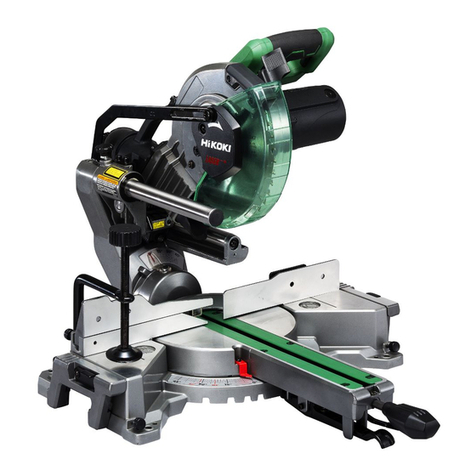
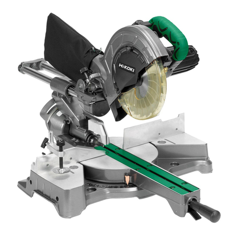
HIKOKI C 10FCE2 User manual

Compound Miter Saw
多角度鋸機
콤파운드쏘
Máy cắt góc đa năng
แทนตัดองศา
C10FCH2 •C10FCE2
Handling instructions Hướng dẫn sử dụng
使用說明書 คูมือการใชงาน
취급 설명서
Read through carefully and understand these instructions before use.
使用前務請詳加閱讀
본 설명서를 자세히 읽고 내용을 숙지한 뒤 제품을 사용하십시오.
Đọc kỹ và hiểu rõ các hướng dẫn này trước khi sử dụng.
โปรดอานโดยละเอียดและทําความเขาใจกอนใชงาน
000BookC10FCH2Ara.indb1000BookC10FCH2Ara.indb1 2018/03/089:07:452018/03/089:07:45

2
000BookC10FCH2Ara.indb2000BookC10FCH2Ara.indb2 2018/03/089:07:462018/03/089:07:46

3
000BookC10FCH2Ara.indb3000BookC10FCH2Ara.indb3 2018/03/089:07:472018/03/089:07:47

4
000BookC10FCH2Ara.indb4000BookC10FCH2Ara.indb4 2018/03/089:07:472018/03/089:07:47

5
000BookC10FCH2Ara.indb5000BookC10FCH2Ara.indb5 2018/03/089:07:482018/03/089:07:48

6
English 中國語 한국어
1Handle 手柄 핸들
2Motor Head 電動頭 모터 헤드
3Gear Case 齒輪箱 기어 케이스
4Dust Bag 防塵袋 분진 주머니
5Laser Marker (Only C10FCH2) 鐳射標記器(僅C10FCH2) 레이저 마커
6Vise Assembly 虎鉗組件 바이스 어셈블리
7Sub Fence (B) 小擋板(B) 서브 펜스(B)
8Fence (B) 擋板(B) 펜스(B)
9Turntable 回轉台 턴테이블
0Side Handle 側手柄 사이드 핸들
!Lever 連杆 레버
@Indicator (A) (For miter scale) 指針(A)(用於斜接尺) 표시(A)(연귀 눈금)
#Table Insert 導板 테이블 인서트
$Fence (A) 擋板(A) 펜스(A)
%Indicator (B) (For bevel scale) 指針(B)(用於角尺) 표시 (B)(경사 눈금)
^Lower Guard 下部安全罩 하부 보호대
&Saw Blade 鋸片 톱날
*Motor 電動機 모터
(Nameplate 銘牌 명판
)Trigger Switch 開關 작동 스위치
qSwitch (For laser marker)
(Only C10FCH2)
開關(用於鐳射標記器)
(僅C10 F CH2)
스위치(레이저 마커)
(C10FCH2만 해당)
wBase 底座 베이스
eHolder (B) 支架(B) 홀더(B)
rClamp Lever 夾緊杆 클램프 레버
tLocking Pin 插銷 잠금 핀
yDuct 導管 덕트
uRight Angle 直角 직각
iLine 直線 선
oWarning Sign 線警告標誌 경고 표시
p6 mm Bolt 6 mm螺栓 6 mm 볼트
aM6 20 Screw M6 20 螺絲 M6 × 20 나사
sScrew Holder 螺絲支架 나사 홀더
d6 mm Wing Bolt (B) 6 mm 翼栓(B) 6 mm 윙 볼트 (B)
fVise Shaft 虎鉗軸 바이스 축
g6 mm Wing Bolt (A) 6 mm 翼栓(A) 6 mm 윙 볼트 (A)
000BookC10FCH2Ara.indb6000BookC10FCH2Ara.indb6 2018/03/089:07:482018/03/089:07:48

7
English 中國語 한국어
hWorkpiece 工件 작업물
jVise Plate 虎鉗板 바이스 플레이트
kKnob 旋鈕 손잡이
lM6 Flat screw M6 一字螺絲 M6 접시 머리 나사
;Plate (A) 平板(A) 플레이트 (A)
zM6 Nylon nut M6 尼龍螺帽 M6 나일론 너트
xM10 Bolt M10 螺栓 M10 볼트
cLaser line 激光線 레이저 선
vGroove 凹槽 홈
b4 mm Hex. Bar Wrench 4 mm 六角條形扳手 4 mm 육각봉 렌치
nMarking (pre-marked) 標誌(預先標記) 표시(사전 표시됨)
mMiter Scale 斜接尺 연귀 눈금
,Holder (Optional accessory) 支架(選購件) 홀더(옵션 부속품)
.Steel Square 方鋼 곱자
/6 mm Wing Nut
(Optional accessory) 6 mm翼狀螺母(選購件) 6 mm 윙 너트(옵션 부속품)
¡Height Adjustment Bolt 6 mm
(Optional accessory) 高度調節螺栓6 mm(選購件) 6 mm 높이 조정 볼트
(옵션 부속품)
™Base Surface 底座面 베이스 표면
£6 mm Wing Bolt
(Optional accessory) 6 mm旋鈕螺栓(選購件) 6 mm 윙 볼트(옵션 부속품)
¢Stopper (Optional accessory) 止動片(選購件) 스토퍼(옵션 부속품)
∞6 mm Wing Bolt (B)
(Optional accessory) 6 mm 翼栓(B)(選 購件) 6 mm 윙 볼트 (B)(옵션 부속품)
§6 mm Wing Bolt 6 mm 翼栓 6 mm 윙 볼트
¶Crown Molding vise ass'y (L)
(Optional accessory) 冠狀模塑虎鉗組件(L)(選 購件) 크라운 몰딩 바이스 어셈블리 (L)
(옵션 부속품)
•6 mm Wing Bolt 6 mm 翼栓 6 mm 윙 볼트
ª6 mm Wing Bolt 6 mm 翼栓 6 mm 윙 볼트
ºCrown Molding Stopper (L)
(Optional accessory) 冠狀模塑止動片(L)(選購件) 크라운 몰딩 스토퍼 (L)
(옵션 부속품)
⁄Crown Molding Stopper (R)
(Optional accessory) 冠狀模塑止動片(R)(選購件) 크라운 몰딩 스토퍼 (R)
(옵션 부속품)
¤6 mm Knob Bolt 6 mm旋鈕螺栓 6 mm 손잡이 볼트
‹Knob 旋鈕 손잡이
›Crown molding 冠狀模塑 크라운 몰딩
fiSpindle Lock 主軸鎖 스핀들 잠금 장치
000BookC10FCH2Ara.indb7000BookC10FCH2Ara.indb7 2018/03/089:07:482018/03/089:07:48

8
English 中國語 한국어
fl10 mm Box Wrench 10 mm套筒扳手 10 mm 박스 렌치
‡Washer (B) 墊圈(B) 와셔 (B)
°Bolt 螺栓 볼트
·Washer 墊圈 와셔
‚Washer (A) 墊圈(A) 와셔 (A)
ŒCollar (B) 軸環(B) 칼라 (B)
„Hex. Head Bolt 六角頭螺栓 육각 머리 볼트
´Steel Square 方鋼 곱자
‰Wear limit line 磨損極限 마모 한계선
ˇGroove for Driver 用於起子的凹槽 드라이버용 홈
ÁBrush Cap 碳刷蓋 브러시 캡
000BookC10FCH2Ara.indb8000BookC10FCH2Ara.indb8 2018/03/089:07:482018/03/089:07:48

9
Tiếng Việt ไทย
1Tay nắm มือจับ
2Động cơ หัวมอเตอร
3Hộp số เรือนเฟอง
4Túi lọc bụi ถุงเก็บฝุน
5Máy đánh dấu laser (Chỉ C10FCH2) เครื่องยิงเลเซอร (เฉพาะ C10FCH2)
6Bàn kẹp ชุดแทนจับ
7Lá chắn phụ (B) แนวฉากยอย (B)
8Lá chắn (B) ฉาก (B)
9Đĩa quay แทนหมุน
0Tay nắm bên มือจับดานขาง
!Cần gạt แปน
@Thước đo (A) (Để cân góc) สัญลักษณ (A) (สําหรับเครื่องวัดองศา)
#Đệm lót bàn แผนเสียบคํ้า
$Lá chắn (A) ฉาก (A)
%Thước đo (B) (Để đo góc xiên) สัญลักษณ (B) (สําหรับเครื่องวัดมุม)
^Tấm chắn dưới ชิ้นสวนปองกันชวงลาง
&Lưỡi cưa ใบเลื่อย
*Động cơ มอเตอร
(Bảng tên แผนปายชื่อ
)Công tắc khởi động สวิตชไก
qCông tắc (Dùng cho máy đánh dấu
laser) (Chỉ C10FCH2) สวิตช (สําหรับเครื่องยิงเลเซอร)
(เฉพาะ C10FCH2)
wChân bệ ฐาน
eGiá đỡ (B) ฐานรอง (B)
rĐòn bẩy kẹp แปนยึด
tChốt an toàn สลักล็อค
yỐng dẫn ราง
uGóc vuông มุมฉาก
iDây แนว
oDấu hiệu cảnh báo ปายเตือน
pBu lông 6 mm สลักเกลียว 6 มม.
aĐinh vít M6 × 20 สกรู M6 x 20
sGiá đỡ đinh vít ดามจับสกรู
dBu lông tai chuồn 6 mm (B) สลักเกลียวปกผีเสื้อ 6 มม. (B)
fTrục kẹp แกนแทนจับ
gBu lông tai chuồn 6 mm (A) สลักเกลียวปกผีเสื้อ 6 มม. (A)
000BookC10FCH2Ara.indb9000BookC10FCH2Ara.indb9 2018/03/089:07:482018/03/089:07:48

10
Tiếng Việt ไทย
hVật liệu gia công ชิ้นงาน
jTấm kẹp แผนรองแทนจับ
kNút bấm ปุมหมุน
lĐinh vít đầu phẳng M6 สกรูหัวแบน M6
;Tấm (A) แผนรอง (A)
zĐai ốc nylon M6 น็อตไนลอน M6
xBu lông M10 สลักเกลียว M10
cVạch laser แนวเลเซอร
vRãnh แนวรอง
bChìa vặn lục giác 4mm ประแจเลื่อนหกเหลี่ยม 4 มม.
nĐánh dấu (Vạch sẵn) เครื่องหมายกํากับ (กํากับเบื้องตน)
mCân góc เครื่องวัดองศา
,Giá đỡ (Phụ tùng tùy chọn) ฐานจับ (อุปกรณเสริม)
.Thép hộp chữ nhật ฉากเหล็ก
/Đai ốc tai chuồn 6 mm
(phụ tùng tùy chọn) น็อตปกผีเสื้อ 6 มม.
(อุปกรณเสริม)
¡Vít điều chỉnh độ cao 6 mm
(phụ tùng tùy chọn) สลักเกลียวปรับความสูง 6 มม.
(อุปกรณเสริม)
™Bề mặt chân đế พื้นผิวสวนฐานรองรับ
£Bu lông tai chuồn 6 mm
(phụ tùng tùy chọn) สลักเกลียวปกผีเสื้อ 6 มม.
(อุปกรณเสริม)
¢Chốt chặn (phụ tùng tùy chọn) ตัวกั้นระยะ (อุปกรณเสริม)
∞Bu lông tai chuồn 6 mm (B)
(phụ tùng tùy chọn) สลักเกลียวปกผีเสื้อ 6 มม. (B)
(อุปกรณเสริม)
§Bu lông tai chuồn 6 mm สลักเกลียวปกผีเสื้อ 6 มม.
¶Bàn kẹp gờ (L)
(phụ tùng tùy chọn) ชุดแทนจับบัวประกบ (L)
(อุปกรณเสริม)
•Bu lông tai chuồn 6 mm สลักเกลียวปกผีเสื้อ 6 มม.
ªBu lông tai chuồn 6 mm สลักเกลียวปกผีเสื้อ 6 มม.
ºChốt chặn gờ (L)
(phụ tùng tùy chọn) ตัวกั้นระยะบัวประกบ (L)
(อุปกรณเสริม)
⁄Chốt chặn gờ (R)
(phụ tùng tùy chọn) ตัวกั้นระยะบัวประกบ (R)
(อุปกรณเสริม)
¤Chốt tay nắm 6 mm สลักเกลียวหัวแปนหมุน 6 มม.
‹Tay nắm ปุมหมุน
›Gờ บัวประกบ
fiKhóa hãm trục ล็อคแกนหมุน
000BookC10FCH2Ara.indb10000BookC10FCH2Ara.indb10 2018/03/089:07:482018/03/089:07:48

11
Tiếng Việt ไทย
flChìa vặn kiểu ống 10 mm ประแจแหวน 10 มม.
‡Vòng đệm (B) แหวนรอง (B)
°Bu lông สลักเกลียว
·Vòng đệm แหวนรอง
‚Vòng đệm (A) แหวนรอง (A)
ŒBích (B) ปลอก (B)
„Bu lông đầu hình lục giác สลักเกลียวหัวหกเหลี่ยม
´Thép hộp chữ nhật ฉากเหล็ก
‰Vạch giới hạn mòn แนวกันสึก
ˇRãnh dẫn động รองสําหรับหัวขัน
ÁNắp chổi ฝาครอบแปรง
000BookC10FCH2Ara.indb11000BookC10FCH2Ara.indb11 2018/03/089:07:492018/03/089:07:49

English
12
GENERAL OPERATIONAL PRECAUTIONS
WARNING! When using electric tools, basic safety
precautions should always be followed to reduce the risk
of fire, electric shock and personal injury, including the
following.
Read all these instructions before operating this product and
save these instructions.
For safe operations:
1. Keep work area clean. Cluttered areas and benches
invite injuries.
2. Consider work area environment. Do not expose
power tools to rain. Do not use power tools in damp or
wet locations. Keep work area well lit.
Do not use power tools where there is risk to cause fire
or explosion.
3. Guard against electric shock. Avoid body contact with
earthed or grounded surfaces (e.g. pipes, radiators,
ranges, refrigerators).
4. Keep children and infirm persons away. Do not let
visitors touch the tool or extension cord. All visitors
should be kept away from work area.
5. Store idle tools. When not in use, tools should be
stored in a dry, high or locked up place, out of reach of
children and infirm persons.
6. Do not force the tool. It will do the job better and safer
at the rate for which it was intended.
7. Use the right tool. Do not force small tools or
attachments to do the job of a heavy duty tool. Do not
use tools for purposes not intended; for example, do
not use circular saw to cut tree limbs or logs.
8. Dress properly. Do not wear loose clothing or jewelry,
they can be caught in moving parts. Rubber gloves
and non-skid footwear are recommended when
working outdoors. Wear protecting hair covering to
contain long hair.
9. Use eye protection. Also use face or dust mask if the
cutting operation is dusty.
10. Connect dust extraction equipment.
Cutting operation by this compound miter saw may
produce considerable amount of dust from extraction
duct on fixed guard.
(Dust material: Wood or Aluminium)
If devices are provided for the connection of dust
extraction and collection facilities ensure these are
connected and properly used.
11. Do not abuse the cord. Never carry the tool by the cord
or yank it to disconnect it from the receptacle. Keep
the cord away from heat, oil and sharp edges.
12. Secure work. Use clamps or a vise to hold the work. It
is safer than using your hand and it frees both hands
to operate tool.
13. Do not overreach. Keep proper footing and balance at
all times.
14. Maintain tools with care. Keep cutting tools sharp
and clean for better and safer performance. Follow
instructions for lubrication and changing accessories.
Inspect tool cords periodically and if damaged, have
it repaired by authorized service center. Inspect
extension cords periodically and replace, if damaged.
Keep handles dry, clean, and free from oil and grease.
15. Disconnect tools. When not in use, before servicing,
and when changing accessories such as blades, bits
and cutters.
16. Remove adjusting keys and wrenches. Form the habit
of checking to see that keys and adjusting wrenches
are removed from the tool before turning it on.
17. Avoid unintentional starting. Do not carry a plugged-
in tool with a finger on the switch. Ensure switch is off
when plugging in.
18. Use outdoor extension leads. When tool is used
outdoors, use only extension cords intended for
outdoor use.
19. Stay alert. Watch what you are doing. Use common
sense. Do not operate tool when you are tired.
20. Check damaged parts. Before further use of the tool, a
guard or other part that is damaged should be carefully
checked to determine that it will operate properly and
perform its intended function. Check for alignment of
moving parts, free running of moving parts, breakage
of parts, mounting and any other conditions that
may affect its operation. A guard or other part that is
damaged should be properly repaired or replaced
by an authorized service center unless otherwise
indicated in this handling instructions. Have defective
switches replaced by an authorized service center. Do
not use the tool if the switch does not turn it on and off.
21. Warning
The use of any accessory or attachment, other than
those recommended in this handling instructions, may
present a risk of personal injury.
22. Have your tool repaired by a qualified person.
This electric tool is in accordance with the relevant
safety requirements. Repairs should only be carried
out by qualified persons using original spare parts.
Otherwise this may result in considerable danger to
the user.
PRECAUTIONS ON USING COMPOUND MITER
SAW
1. Keep the floor area around the machine level. Well
maintained and free of loose materials e.g. chips and
cut-offs.
2. Provide adequate general or localized lighting.
3. Do not use power tools for applications other than
those specified in the handling instructions.
4. Repairing must be done only by authorized service
facility. Manufacturer is not responsible for any damages
and injuries due to the repair by the unauthorized persons
as well as the mishandling of the tool.
5. To ensure the designed operational integrity of power
tools, do not remove installed covers or screws.
6. Do not touch movable parts or accessories unless the
power source has been disconnected.
7. Use your tool at lower input than specified on the
nameplate; otherwise, the finish may be spoiled and
working efficiency reduced due to motor overload.
8. Do not wipe plastic parts with solvent. Solvents such
as gasoline, thinner, benzine, carbon tetrachloride,
alcohol, may damage and crack plastic parts. Do not
wipe them with such solvent. Clean plastic parts with a
soft cloth lightly dampened with soapy water.
9. Use only original HiKOKI replacement parts.
10. This tool should only be disassembled for replacement
of carbon brushes.
11. The exploded assembly drawing on this handling
instructions should be used only for authorized service
facility.
12. Never cut ferrous metals or masonry.
13. Adequate general or localized lighting is provided.
Stock and finished workpieces are located close to the
operators normal working position.
14. Wear suitable personal protective equipment when
necessary, this could include:
Hearing protection to reduce the risk of induced
hearing loss.
Eye protection to reduce the risk of injuring an eye.
Respiratory protection to reduce the risk of inhalation
of harmful dust.
000BookC10FCH2Ara.indb12000BookC10FCH2Ara.indb12 2018/03/089:07:492018/03/089:07:49

English
13
Gloves for handling saw blades (saw blades shall be
carried in a holder wherever practicable) and rough
material.
15. The operator is adequately trained in the use,
adjustment and operation of the machine.
16. Refrain from removing any cut-offs or other parts of the
workpiece from the cutting area whilst the machine is
running and the saw head is not in the rest position.
17. Never use the compound miter saw with its lower
guard locked in the open position.
18. Ensure that the lower guard moves smoothly.
19. Do not use the saw without guards in position, in good
working order and properly maintained.
20. Use correctly sharpened saw blades. Observe the
maximum speed marked on the saw blade.
21. D o not u se s aw blades which are damaged or
deformed.
22. Do not use saw blades manufactured from high speed
steel.
23. Use only saw blades recommended by HiKOKI.
24. The saw blades should be from 235 mm to 255 mm
external diameter ranges.
25. Select the correct saw blade for the material to be cut.
26. Never operate the compound miter saw with the saw
blade turned upward or to the side.
27. Ensure that the workpiece is free of foreign matter
such as nails.
28. Replace the table insert when worn.
29. Do not use the saw to cut other than aluminium, wood
or similar materials.
30. Do not use the saw to cut other materials than those
recommended by the manufacturer.
31. Blade replacement procedure, including the method
for repositioning and a warning that this must be
carried out correctly.
32. Connect the compound miter saw to a dust collecting
device when sawing wood.
33. Take care when slotting.
34. When transporting or carrying the tool, do not grasp
the holder. Grasp the handle instead of the holder.
35. Start cutting only after motor revolution reaches
maximum speed.
36. Promptly cut OFF the switch when abnormality
observed.
37. Shut offpower and wait for saw blade to stop before
servicing or adjusting tool.
38. During a miter or bevel cut the blade should not be
lifted until it has stopped rotation completely.
39. Take all the possibility of residual risks in cutting
operation into your consideration, such as the laser
radiation to your eyes, the inadvertent access to moving
parts on slide mechanical parts on machine and so on.
SPECIFICATIONS
Max. Cutting Capacity
Height × Width
0°
59 mm × 144 mm
or
89 mm × 101 mm
Miter 45° 59 mm × 102 mm
Bevel Left 45° 41 mm × 144 mm
Compound (Bevel Left 45°, Miter 45°) 41 mm × 102 mm
Saw Blade Dimensions (oD × iD × Thickness) 255 mm × 25.4 mm × 2.7 mm
Miter Cutting Angle Right and Left 0° – 52°
Bevel Cutting Angle Left 0° – 45°
Compound Cutting Angle Miter (Right and Left) 0° – 45°
Voltage (by areas)* (110 V, 120 V, 127 V, 220 V, 230 V, 240 V)
Power Input* 1520 W
No-Load Speed* 5000/min
Machine Dimensions (Width × Depth × Height) 460 mm × 628 mm × 561 mm
Weight (Net) 12 kg (C10FCH2)/11.9 kg (C10FCE2)
Laser Marker
(Only model C10FCH2)
Maximum output Po<3 mW Class Laser Product
(Iambda) 654 nm
Laser medium Laser Diode
* Be sure to check the nameplate on product as it is subject to change by areas
000BookC10FCH2Ara.indb13000BookC10FCH2Ara.indb13 2018/03/089:07:492018/03/089:07:49

English
14
STANDARD ACCESSORIES
(1) 255 mm TCT Saw blade (mounted on tool) .................1
(2) Dust bag ......................................................................1
(3) 10 mm Box wrench......................................................1
(4) Vise Assembly.............................................................1
(5) 4 mm Hex. bar wrench (Only C10FCH2) .....................1
(6) Sub Fence ..................................................................1
(7) Flat screw ....................................................................1
(8) M6 Nylon nut ...............................................................1
(9) Plate (A) ......................................................................1
(10) Holder (B)....................................................................1
(11) Side handle .................................................................1
Standard accessories are subject to change without notice.
OPTIONAL ACCESSORIES (sold separately)
(1) Extension Holder and Stopper
(2) Crown molding Vise Ass'y (Include Crown molding
Stopper (L))
(3) Crown molding Stopper (L)
(4) Crown molding Stopper (R)
Optional accessories are subject to change without notice.
APPLICATION
○Cutting various types of aluminium sash and wood.
UNPACKING
○Carefully unpack the power tool and all related items
(standard accessories).
○Check carefully to make cer tain all related items
(standard accessories) are present.
PRIOR TO OPERATION
1. Power source
Ensure that the power source to be utilized conforms
to the power requirements specified on the product
nameplate.
2. Power switch
Ensure that the power switch is in the OFF position. If
the plug is connected to a receptacle while the trigger
switch is in the ON position, the power tool will start
operating immediately, inviting serious accident.
3. Extension cord
When the work area is removed from the power source,
use an extension cord of sufficient thickness and rated
capacity. The extension cord should be kept as short
as practicable.
4. When the power tool is prepared for shipping, its
main parts are secured by a locking pin
Move the handle slightly so that the locking pin can be
disengaged.
During transport, lock the locking pin into the gear
case (Fig. 3).
5. Attach the dust bag to the main unit (Fig. 1)
(1) When the dust bag has become full of sawdust, dust
will be blown out of the dust bag when the saw blade
rotates.
Check the dust bag periodically and empty it before it
becomes full.
(2) During bevel and compound cutting, attach the dust bag
at a right angle to the base surface as shown in Fig. 4.
CAUTION
Empty the dust bag frequently to prevent the duct and
the lower guard from becoming clogged.
Sawdust will accumulate more quickly than normal
during bevel cutting.
6. Installation
Ensure that the machine is always fixed to bench.
Attach the power tool to a level, horizontal work bench.
Select 8 mm diameter bolts suitable in length for the
thickness of the work bench.
Bolt length should be at least 35 mm plus the thickness
of the work bench.
For example, use 8 mm × 60 mm bolts for a 25 mm
thick work bench.
ADJUSTING THE POWER TOOL PRIOR TO USE
CAUTION
Make all necessary adjustments before inserting the
plug in the power source.
1. Check to see that the lower guard operates smoothly
PRACTICAL APPLICATIONS
WARNING
○ To avoid personal injur y, never remove or place a
workpiece on the table while the tool is being operated.
○ Never place your limbs inside of the line nex t to
warning sign while the tool is being operated. This may
cause hazardous conditions (see Fig. 5).
CAUTION
○ It is dangerous to remove or install the workpiece while
the saw blade is turning.
○ When sawing, clean offthe shavings from the turntable.
○ If the shavings accumulate too much, the saw blade
from the cutting material will be exposed. Never
subject your hand or anything else to go near the
exposed blade.
1. Tightly secure the material by vise assembly to be
cut so that it does not move during cutting
2. Switch operation
Pulling the trigger turns the switch on. Releasing the
trigger turns the switch off.
3. Holder (B), clamp lever adjustment (Fig. 6)
At tach the included holder (B) in the position as
shown in Fig. 6 and adjust the holder (B) until its
bottom surface contacts the work bench surface. After
adjustments, securely tighten the 6mm bolt with the
included 10mm box wrench. Loosen the M6 20 screw
on the clamp lever and attach to a position where the
clamp lever can be easily operated.
4. Using the Vise Assembly (Standard accessory) (Fig. 7)
(1) The vise assembly can be mounted on either the left
fence {Fence (B)} or the right fence {Fence (A)} by
loosening the 6 mm wing bolt (A).
(2) The screw holder can be raised or lowered according
to the height of the workpiece by loosening the 6 mm
wing bolt (B). After the adjustment, firmly tighten the 6
mm wing bolt (B) and fix the screw holder.
(3) Turn the upper knob and securely fix the workpiece in
position.
000BookC10FCH2Ara.indb14000BookC10FCH2Ara.indb14 2018/03/089:07:492018/03/089:07:49

English
15
WARNING
Always firmly clamp or vise to secure the workpiece
to the fence; otherwise the workpiece might be thrust
from the table and cause bodily harm.
CAUTION
Always confirm that the motor head does not contact
the vise assembly when it is lowered for cutting. If there
is any danger that it may do so, loosen the 6 mm wing
bolt and move the vise assembly to a position where it
will not contact the saw blade.
5. Install the sub fence (B) (Fig. 8)
In the case of direct angle cutting and angle cutting,
use the sub fence. The sub fence (B) can be installed
on the right side of the guide fence (B). Place
the at tached plate (A) in the position as shown in
Fig. 8, insert the tip in the groove of fence (B) and
simultaneously, insert flathead screw M6 into fence (B),
sub fence (B), and plate (A), then tighten nylon nut M6
with the included 10mm box wrench until the sub fence
(B) can smoothly rotate. Then, you can realize stable
cutting of the material with a wide back face.
WARNING
In the case of left bevel cutting, rotate the sub fence (B).
Supposing it is not able to rotate it, it will contact the
blade or some part of the tool, causing in serious injury
to operator.
6. Using an ink line
Upon lowering the motor section, the lower guard is
raised and the saw blade appears.
Align the ink line with the saw blade.
CAUTION
Never lift the lower guard while the saw blade is
rotating.
The sub fence will not only make contact and adversely
affect cutting accuracy, this could also result in
damage to the guard.
7. Install the side handle (Fig. 9)
Remove the M10 bolt and install the side handle that
came enclosed with this unit.
8. Position adjustment of laser line (Only model
C10FCH2)
Ink lining can be easily made on this tool to the laser
marker. A switch lights up the laser marker (Fig. 10).
Depending upon your cutting choice, the laser line can
be aligned with the left side of the cutting width (saw
blade) or the ink line on the right side.
The laser line is adjusted to the width of the saw blade
at the time of factory shipment. Adjust the positions of
the saw blade and the laser line taking the following
steps to suit the use of your choice.
(1) Light up the laser marker and make a groove of
about 5 mm deep on the workpiece that is about 38
mm in height and 89 mm in width. Hold the grooved
workpiece by vise as it is and do not move it.
(2) Then insert a 4 mm hex. bar wrench in the 12 diameter
hole on the side of the gear case, turn the hex. socket
set screw to move the laser line. (If you turn the Hex.
socket screw clockwise, the laser line will shift to the
right and if you turn it counterclockwise, the laser line
will shift to the left.) When you work with the ink line
aligned with the left side of the saw blade, align the
laser line with the left end of the groove (Fig. 11). When
you align it with the right side of the saw blade, align
the laser line with the right side of the groove.
(3) After adjusting the position of the laser line, draw a
right-angle ink line on the workpiece and align the
ink line with the laser line. When aligning the ink line,
slide the workpiece little by little and secure it by
vise at a position where the laser line overlaps with
the ink line. Work on the grooving again and check
the position of the laser line. If you wish to change
the laser line’s position, make adjustments again
following the steps from (1) to (3).
WARNING (Fig. 13 and Fig. 14)
○Make sure before plugging the power plug into the
receptacle that the main body and the laser marker are
turned off.
○Exercise utmost caution in handling a switch trigger for
the position adjustment of the laser line, as the power
plug is plugged into the receptacle during operation.
If the switch trigger is pulled inadvertently, the saw
blade can rotate and result in unexpected accidents.
○Do not remove the laser marker to be used for other
purposes.
CAUTION
○Laser radiation - Do not stare into beam.
○Laser radiation on work table. Do not stare into beam.
If your eye is exposed directly to the laser beam, it can
be hurt.
○Do not dismantle it.
○Do not give strong impact to the laser marker (main
body of tool); otherwise, the position of a laser line can
go out of order, resulting in the damage of the laser
marker as well as a shortened service life.
○Keep the laser marker lit only during a cutting
operation. Prolonged lighting of the laser marker can
result in a shortened service life.
○Use of controls or adjustments or performance of
procedures other than those specified herein may
result in hazardous radiation exposure.
NOTE
○Perform cutting by overlapping the ink line with the
laser line.
○When the ink line and the laser line are overlapped, the
strength and weakness of light will change, resulting
in a stable cutting operation because you can easily
discern the conformit y of lines. This ensures the
minimum cutting errors.
○In outdoor or near-the -window operations, it may
become difficult to observe the laser line due to the
sunlight. Under such circumstances, move to a place
that is not directly under the sunlight and engage in the
operation.
○Do not tug on the cord behind the motor head or hook
your finger, wood and the like around it; otherwise, the
cord may come offand the laser marker may not be lit
up.
○Check and make sure on a periodic basis if the position
of the laser line is in order. As regards the checking
method, draw a right-angle ink line on the workpiece
with the height of about 38 mm and the width of 89
mm, and check that the laser line is in line with the ink
line [The deviation between the ink line and the laser
line should be less than the ink line width (0.5 mm)]
(Fig. 12).
9. Cutting operation
(1) As shown in Fig. 15 the width of the saw blade is the
width of the cut. Therefore, slide the workpiece to the
right (viewed from the operator’s position) when length
is desired, or to the left when length is desired.
(Only model C10FCH2)
If a laser marker is used, align the laser line with the left
side of the saw blade, and then align the ink line with
the laser line.
000BookC10FCH2Ara.indb15000BookC10FCH2Ara.indb15 2018/03/089:07:492018/03/089:07:49

English
16
(2) Once the saw blade reaches maximum speed, slowly
push down the handle and bring the saw blade in the
vicinity of the material to be cut.
(3) Once the saw blade contacts the workpiece, push the
handle down gradually to cut into the workpiece.
(4) After cutting the workpiece to the desired depth,
turn the power tool OFF and let the saw blade
stop completely before raising the handle from the
workpiece to return it to the full retract position.
CAUTION
○For ma ximum dimensions for cutting, refer to
“SPECIFICATIONS” table.
○Increased pressure on the handle will not increase
the cutting speed. On the contrary, too much pressure
may result in overload of the motor and/or decreased
cutting efficiency.
○Confirm that the trigger switch is turned OFF and the
power plug has been removed from the receptacle
whenever the tool is not in use.
○Always turn the power of f and let the saw blade
stop completely before raising the handle from the
workpiece. If the handle is raised while the saw blade
is still rotating, the cut-offpiece may become jammed
against the saw blade causing fragments to scatter
about dangerously.
○Every time one cutting of deep-cutting operation is
finished, turn the switch off, and check that the saw
blade has stopped. Then raise the handle, and return it
to the full retract position.
○Be absolutely sure to remove the cut material from the
top of the turntable, and then proceed to the next step.
10. Miter cutting procedures
(1) Loosen the side handle and push the lever for angle
stoppers. Then, adjust the turntable until the indicator
aligns with desired setting on the miter scale (Fig. 16).
(2) Re-tighten the side handle to secure the turntable in
the desired position.
NOTE
○Positive stops are provided at the right and left of the
0° center setting, at 15°, 22.5°, 31.6° and 45° settings.
Check that the miter scale and the tip of the indicator
are properly aligned.
○Operation of the saw with the miter scale and indicator
out of alignment, or with the side handle not properly
tightened, will result in poor cutting precision.
CAUTION
Never remove the side handle; use of the tool without it
would be hazardous.
To prevent an accident or personal injury always firmly
tighten the miter handle.
11. Bevel cutting procedures (Fig. 17 and Fig. 18)
(1) Loosen the clamp lever and bevel the saw blade to the
left.
(2) Adjust the bevel angle to the desired setting while
watching the bevel angle scale and indicator, then
secure the clamp lever.
WARNING
○When the workpiece is secured on the left or right side
of the blade, the short cut-offportion will come to rest
on the right or left side of the saw blade. Always turn
the power off and let the saw blade stop completely
before raising the handle from the workpiece.
If the handle is raised while the saw blade is still
rotating, the cut-offpiece may become jammed against
the saw blade causing fragments to scatter about
dangerously.
○When stopping the bevel cutting operation halfway,
start cutting after pulling back the motor head to the
initial position.
Starting from halfway, without pulling back, causes the
safety cover to be caught in the cutting groove of the
workpiece and to contact the saw blade.
12. Compound cutting procedures
Compound cutting can be per formed by following
the instructions in 9 and 10 above. For maximum
dimensions for compound cutting, refer to
“SPECIFICATIONS” table.
CAUTION
Always secure the workpiece with the right hand side
for compound cutting. Never rotate the table to the
right for compound cutting, because the saw blade
might then contact the clamp or vise that secures the
workpiece, and cause personal injury or damage.
13. Installing the holders (Optional accessory)
The holders help keep longer workpieces stable and in
place during the cutting operation.
(1) As indicated in Fig. 19, use a steel square for aligning
the upper edge of the holders with the base surface.
Loosen the 6 mm wing nut. Turn a height adjustment
bolt 6 mm, and adjust the height of the holder.
(2) Af ter adjustment, firmly tighten the wing nut and
fasten the holder with the 6 mm knob bolt (optional
accessory). If the length of Height Adjustment Bolt 6
mm is insufficient, spread a thin plate beneath. Make
sure the end of Height Adjustment Bolt 6 mm does not
protrude from the holder.
14. Stopper for precision cutting (Stopper and holder
are optional accessory)
The stopper facilitates continuous precision cutting in
lengths of 280 mm to 450 mm.
To install the stopper, attach it to the holder with the 6
mm wing bolt as shown in Fig. 20.
15. Confirmation for use Crown molding vise, Crown
molding Stopper (L) and (R) (Optional accessory)
(1) Crown molding Stopper (L) and (R) (optional
accessories) allow easier cuts of crown molding
without tilting the saw blade. lnstall them in the base
both-sides side to be shown in Fig. 21. After inserting
tighten the 6 mm knob bolts to secure the Crown
molding Stoppers.
(2) The crown molding vise (B) (Optional accessory) can
be mounted on either the left fence (Fence (B)) or the
right fence (Fence (A)). lt can unite with the slope of the
crown molding and vice can be pressed down.
Then turn the upper knob, as necessary, to securely
attach the crown molding in position. To raise or lower
the vise assembly, first loosen the 6 mm wing bolt.
After adjusting the height, firmly tighten the 6 mm
wing bolt; then turn the upper knob, as necessary, to
securely attach the crown molding in position (See
Fig. 22).
Position crown molding with its WALL CONTACT
EDGE against the guide fence and its CEILING
CONTACT EDGE against the Crown molding Stoppers
as shown in Fig. 22. Adjust the Crown molding
Stoppers according to the size of the crown molding.
Tighten the 6 mm wing bolt to secure the Crown
molding Stoppers.
WARNING
Always firmly clamp or vise to secure the crown
molding to the fence; otherwise the crown molding
might be thrust from the table and cause bodily harm.
Do not bevel cutting. The main body or saw blade may
contact the sub fence, resulting in an injury.
000BookC10FCH2Ara.indb16000BookC10FCH2Ara.indb16 2018/03/089:07:492018/03/089:07:49

English
17
CAUTION
Always confirm that the motor head (see Fig. 1) does
not contact the crown molding vise assembly when it
is lowered for cutting. If there is any danger that it may
do so, loosen the 6 mm knob bolt and move the crown
molding vise assembly to a position where it will not
contact the saw blade.
MOUNTING AND DISMOUNTING SAW BLADE
WARNING
○To prevent an accident or personal injury, always turn
off the trigger switch and disconnect the power plug
from the receptacle before removing or installing a
blade.
If cutting work is done in a state where the bolt is not
sufficiently tightened, the bolt can get loose, the blade
can come off, and the lower guard can get damaged,
resulting in injuries.
Also, check that the bolts are properly tightened before
plugging the power plug into the receptacle.
○If the bolts are attached or detached using tools other
than the 10 mm box wrench (standard accessor y),
excessive or improperly tightening occurs, resulting in
injury.
1. Mounting the saw blade (Fig. 23, Fig. 24 and Fig. 25)
(1) Rotate the lower guard (plastic) to the top position.
(2) Press in spindle lock and loosen bolt with 10 mm box
wrench (standard accessory).
Since the bolt is left-hand threaded, loosen by turning
it to the right as show in Fig. 24.
NOTE
If the spindle lock cannot be easily pressed in to lock
the spindle, turn the bolt with 10 mm box wrench
(standard accessory) while applying pressure on the
spindle lock.
The saw blade spindle is locked when the spindle lock
is pressed inward.
(3) Remove the bolt and washer (B).
(4) Lift the lower guard and mount the saw blade.
WARNING
When mounting the saw blade, confirm that the rotation
indicator mark on the saw blade and the rotation
direction of the gear case (see Fig. 1) are properly
matched.
(5) Thoroughly clean washer (B) and the bolt, and install
them onto the saw blade spindle.
(6) Press in the spindle lock and tighten the bolt by turning
it to the left by standard accessories wrench(10 mm
box wrench) as indicated in Fig. 24.
CAUTION
○Confirm that the spindle lock has returned to the retract
position after installing or removing the saw blade.
○Tighten the bolt so it does not come loose during
operation.
○Confirm that the bolt has been properly tightened
before the power tool is started.
2. Dismounting the saw blade
Dismount the saw blade by reversing the mounting
procedures described in paragraph 1 above.
The saw blade can easily be removed after lifting the
lower guard.
CAUTION
Never attempt to install saw blades except
235 mm – 255 mm in diameter.
MAINTENANCE AND INSPECTION
WARNING
To avoid an accident or personal injury, always confirm
the trigger switch is turned OFF and that the power
plug has been disconnected from the receptacle
before performing any maintenance or inspection of
this tool.
1. Inspecting the saw blade
Always replace the saw blade immediately upon the
first sign of deterioration or damage.
A damaged saw blade can cause personal injury and
a worn saw blade can cause ineffective operation and
possible overload to the motor.
CAUTION
Never use a dull saw blade. When a saw blade is dull,
its resistance to the hand pressure applied by the tool
handle tends to increase, making it unsafe to operate
the power tool.
2. Inspecting the lever (Fig. 26 and Fig. 27)
If the M8 hexagonal head bolts (2) are loose, align the
sides of the fence and saw blade with the steel square.
After adjusting the saw blade and fence to a ninety-
degree angle, tighten the lever securing hexagonal
head bolts (2).
3. Inspecting the carbon brushes (Fig. 28 and Fig. 29)
The carbon brushes in the motor are expendable parts.
If the carbon brushes become excessively worn, motor
trouble might occur.
Therefore, inspect the carbon brushes periodically and
replace them when they have become worn to the wear
limit line as shown in Fig. 28.
Also, keep the carbon brushes clean so that they will
slide smoothly within the brush holders.
The carbon brushes can easily be removed af ter
removal of the brush caps (see Fig. 29) with a slotted
(minus) screwdriver.
4. About Handling the Motor (see Fig. 1)
Winding of the motor is said to be the heart of this tool.
Exercise utmost caution not to damage the winding by
exposing it to wash oil or water.
NOTE
Accumulation of dust and the like inside the motor can
result in a malfunction.
After using the motor for 50 hours or so, carry out no-
load running, and blow in the dry air from a wind hole at
the motor's rear. Such action is effective to discharge
dust and the like.
5. Inspecting the screws
Regularly inspect each component of the power tool
for looseness.
Re-tighten screws on any loose part.
WARNING
To prevent personal injury, never operate the power
tool if any components are loose.
6. Inspecting the lower guard for proper operation
Before each use of the tool, test the lower guard (see
Fig. 1) to assure that it is in good condition and that it
moves smoothly.
Never use the tool unless the lower guard operates
properly and it is in good mechanical condition.
7. Storage
After operation of the tool has been completed, check
that the following has been performed:
000BookC10FCH2Ara.indb17000BookC10FCH2Ara.indb17 2018/03/089:07:492018/03/089:07:49

English
18
(1) Trigger switch is in OFF position,
(2) Power plug has been removed from the receptacle,
(3) When the tool is not in use, keep it stored in a dry place
out of the reach of children.
8. Lubrication
Lubricate the following sliding surfaces once a month
to keep the power tool in good operating condition for a
long time (Fig. 1 and Fig. 2).
Use of machine oil is recommended.
Oil supply points:
* Rotary portion of hinge
* Rotary portion of vise assembly
9. Cleaning
Periodically remove chips, dust and other waste
material from the surface of the power tool, especially
from the inside of the lower guard with a damp, soapy
cloth. To avoid a malfunction of the motor, protect it
from contact with oil or water.
(Only model C10FCH2)
If the laser line becomes invisible due to chips and
the like adhered onto the window of the laser marker's
light-emitting section, wipe and clean the window with
a dry cloth or a soft cloth moistened with soapy water,
etc.
10. Service parts list
A :I tem No.
B : Code No.
C : No. Used
D : Remarks
CAUTION
Repair, modification and inspection of HiKOKI Power
Tools must be carried out by a HiKOKI Authorized
Service Center.
Especially laser device should be maintained by the
authorised agent by laser manufacturer.
Always assign the repair of laser device to HiKOKI
Authorised Service Center.
This Parts List will be helpful if presented with the
tool to the HiKOKI Authorized Service Center when
requesting repair or other maintenance.
In the operation and maintenance of power tools, the
safety regulations and standards prescribed in each
country must be observed.
MODIFICATIONS
HiKOKI Power Tools are constantly being improved
and modified to incorporate the latest technological
advancements.
Accordingly, some parts (i.e. code numbers and/or
design) may be changed without prior notice.
NOTE
Due to HiKOKI’s continuing program of research and
development the specifications herein are subject to change
without prior notice.
000BookC10FCH2Ara.indb18000BookC10FCH2Ara.indb18 2018/03/089:07:492018/03/089:07:49

中國語
000BookC10FCH2Ara.indb19000BookC10FCH2Ara.indb19 2018/03/089:07:492018/03/089:07:49

中國語
HiKOKI
HiKOKI
000BookC10FCH2Ara.indb20000BookC10FCH2Ara.indb20 2018/03/089:07:512018/03/089:07:51
This manual suits for next models
1
Table of contents
Languages:
Other HIKOKI Saw manuals

HIKOKI
HIKOKI CR 13VC User manual

HIKOKI
HIKOKI C 3605DA User manual

HIKOKI
HIKOKI C 3606DPA User manual

HIKOKI
HIKOKI C 3606DA User manual

HIKOKI
HIKOKI C10FSH User manual

HIKOKI
HIKOKI C 6BUY User manual

HIKOKI
HIKOKI CD 1805DB User manual

HIKOKI
HIKOKI CR13V2NSZ User manual

HIKOKI
HIKOKI CR 14DSL CR User manual

HIKOKI
HIKOKI CR 13V2 User manual

HIKOKI
HIKOKI C 1806DA User manual

HIKOKI
HIKOKI CR 13V2WSZ User manual

HIKOKI
HIKOKI C8FSHE User manual
HIKOKI
HIKOKI CD 3605DA User manual

HIKOKI
HIKOKI C 3605DA User manual

HIKOKI
HIKOKI CD 3605DB User manual

HIKOKI
HIKOKI C 3610DRJX User manual

HIKOKI
HIKOKI C 3612DRA User manual
HIKOKI
HIKOKI C 7ST User manual

HIKOKI
HIKOKI C 3607DA User manual