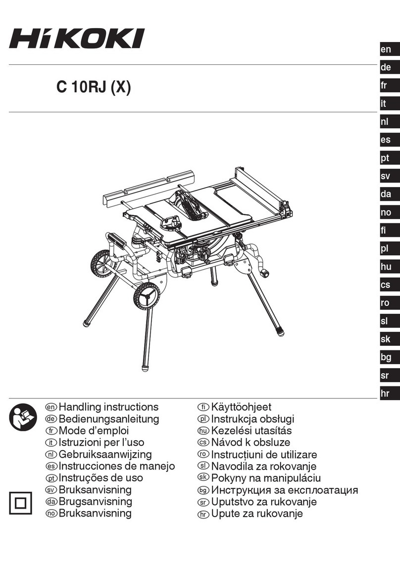
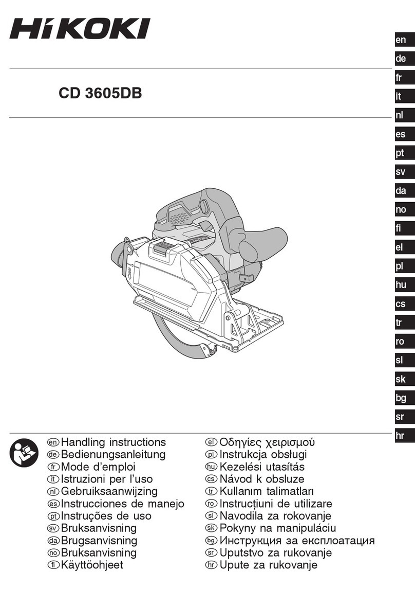
HIKOKI C 3610DRJX User manual

SAFETY INSTRUCTIONS AND INSTRUCTION MANUAL
WARNING
IMPROPER OR UNSAFE use of this power tool can result in death or serious bodily injury!
This manual contains important information about product safety. Please read and understand this manual
BEFORE operating the power tool. Please keep this manual available for other users and owners before
they use the power tool. This manual should be stored in safe place.
Model Cordless Table SawC 3610DRJ (X)

CONTENTS
SECTION
SYMBOLS ..........................................................................................................................................................3
SAFETY INSTRUCTIONS ...................................................................................................................................4
OVERVIEW .......................................................................................................................................................10
SPECIFICATIONS..............................................................................................................................................11
LOOSE PARTS ..................................................................................................................................................12
ASSEMBLY .......................................................................................................................................................13
OPERATION .....................................................................................................................................................22
ADJUSTMENTS ................................................................................................................................................30
MAINTENANCE ................................................................................................................................................32
TROUBLESHOOING ........................................................................................................................................33
SELECTING ACCESSORIES ...........................................................................................................................34
GUARANTEE ....................................................................................................................................................34
PAGE

3
English
The following show symbols used for the machine. Be sure that you understand their meaning before use.
MeaningSymbol
C 3610DRJ (X): Cordless table saw
To reduce the risk of injury, user must read instruction manual.
Always wear eye protection.
Always wear hearing protection.
Danger keep hands away from blade.
Never operate the tool in a damp or wet environment.
Lock / to tighten or secure.
Unlock / to loosen.
Volts
Hertz
Amperes
No load speed
Revolutions per minute
Direct current
Input power
Kilogram
Decibel (A-rated)
Alternating current
V
Hz
A
no
---/min
W
kg
dB(A)
~
Caution, Warning or Danger.
Class II Construction
SYMBOLS

4
English
SAFETY INSTRUCTIONS
The term “power tool” in the warnings refers to your mainsoperated (corded) power tool or battery-operated (cordless) power tool.
1) Work area safety
a) Keep work area clean and well lit. Cluttered or dark areas invite accidents.
b) Do not operate power tools in explosive atmospheres, such as in the presence of flammable liquids, gases or dust.
Power tools create sparks which may ignite the dust or fumes.
c) Keep children and bystanders away while operating a power tool. Distractions can cause you to lose control.
2) Electrical safety
a) Power tool plugs must match the outlet. Never modify the plug in any way. Do not use any adapter plugs with earthed
(grounded) power tools. Unmodified plugs and matching outlets will reduce risk of electric shock.
b) Avoid body contact with earthed or grounded surfaces, such as pipes, radiators, ranges and refrigerators. There is an
increased risk of electric shock if your body is earthed or grounded.
c) Do not expose power tools to rain or wet conditions. Water entering a power tool will increase the risk of electric shock.
d) Do not abuse the cord. Never use the cord for carrying, pulling or unplugging the power tool. Keep cord away from
heat, oil, sharp edges or moving parts. Damaged or entangled cords increase the risk or electric shock.
e) When operating a power tool outdoors, use an extension cord suitable for outdoor use. Use of a cord suitable for outdoor
use reduce the risk of electric shock.
f) If operating a power tool in a damp location is unavoidable, use a RESIDUAL CURRENT DEVICE (RCD) protected supply.
Use of an RCD reduces the risk of electric shock.
3) Personal safety
a) Stay alert, watch what you are doing and use common sense when operating a power tool. Do not use a power tool
while you are tired or under the influence of drugs, alcohol or medication. A moment of inattention while operating power
tools may result in serious personal injury.
b) Use personal protective equipment. Always wear eye protection. Protective equipment such as dust mask, non-skid safety
shoes, hard hat, or hearing protection used for appropriate conditions will reduce personal injuries.
c) Prevent unintentional starting. Ensure the switch is in the off-position before connecting to power source and/or battery
pack, picking up or carrying the tool. Carrying power tools with your finger on the switch or energising power tools that have
the switch on invites accidents.
d) Remove any adjusting key or wrench before turning the power tool on. A wrench or a key left attached to a rotating part of
the power tool may result in personal injury.
e) Do not overreach. Keep proper footing and balance at all times. This enables better control of the power tool in unexpected
situations.
f) Dress properly. Do not wear loose clothing or jewellery. Keep your hair, clothing and gloves away from moving parts.
Loose clothes, jewellery or long hair can be caught in moving parts.
g) If devices are provided for the connection of dust extraction and collection facilities, ensure these are connected and
properly used. Use of dust collection can reduce dust-related hazards.
h) Do not let familiarity gained from frequent use of tools allow you to become complacent and ignore tool safety principles.
A careless action can cause severe injury within a fraction of a second.
4) Power tool use and care
a) Do not force the power tool. Use the correct power tool for your application. The correct power tool will do the job better
and safer at the rate for which it was designed.
b) Do not use the power tool if the switch does not turn it on and off. Any power tool that cannot be controlled with the switch
is dangerous and must be repaired.
c) Disconnect the plug from the power source and/or remove the battery pack, if detachable, from the power tool before
making any adjustments, changing accessories, or storing power tools. Such preventive safety measures reduce the risk
of starting the power tool accidentally.
d) Store idle power tools out of the reach of children and do not allow persons unfamiliar with the power tool or these
instructions to operate the power tool. Power tools are dangerous in the hands of untrained users.
e) Maintain power tools and accessories. Check for misalignment or binding of moving parts, breakage of parts and any
other condition that may affect the power tool’s operation. If damaged, have the power tool repaired before use. Many
accidents are caused by poorly maintained power tools.
f) Keep cutting tools sharp and clean. Properly maintained cutting tools with sharp cutting edges are less likely to bind and are
easier to control.
g) Use the power tool, accessories and tool bits etc. in accordance with these instructions, taking into account the working
conditions and the work to be performed. Use of the power tool for operations different from those intended could result in a
hazardous situation.
h) Keep handles and grasping surfaces dry, clean and free from oil and grease. Slippery handles and grasping surfaces do
not allow for safe handling and control of the tool in unexpected situations.
5) Battery tool use and care
a) Recharge only with the charger specified by the manufacturer. A charger that is suitable for one type of battery pack may
create a risk of fire when used with another battery pack.
b) Use power tools only with specifically designated battery packs. Use of any other battery packs may create a risk of injury
and fire.
General power tool safety warnings
Save all warnings and instructions for future reference.
WARNING: Read all safety warnings, instructions, illustrations and specifications provided with this power tool. Failure to
follow all instructions listed below may result in electric shock, fire and/or serious injury.

5
English
1) Guarding related warnings
a) Keep guards in place. Guards must be in working order and be properly mounted. A guard that is loose, damaged, or is
not functioning correctly must be repaired or replaced.
b) Always use saw blade guard, riving knife and anti-kickback pawls for every through–cutting operation. For through-cutting
operations where the saw blade cuts completely through the thickness of the workpiece, the guard and other safety devices help
reduce the risk of injury.
c) Immediately reattach the guarding system after completing an operation (such as rabbeting) which requires removal
of the guard, riving knife and/or anti-kickback pawls. The guard, riving knife, and anti-kickback pawls help to reduce the risk
of injury.
d) Make sure the saw blade is not contacting the guard, riving knife or the workpiece before the switch is turned
on. Inadvertent contact of these items with the saw blade could cause a hazardous condition.
e) Adjust the riving knife as described in this instruction manual. Incorrect spacing, positioning and alignment can make the
riving knife ineffective in reducing the likelihood of kickback.
f) For the riving knife and anti-kickback pawls to work, they must be engaged in the workpiece. The riving knife and anti-
kickback pawls are ineffective when cutting workpieces that are too short to be engaged with the riving knife and anti-kickback
pawls. Under these conditions a kickback cannot be prevented by the riving knife and anti-kickback pawls.
g) Use the appropriate saw blade for the riving knife. For the riving knife to function properly, the saw blade diameter must match
the appropriate riving knife and the body of the saw blade must be thinner than the thickness of the riving knife and the cutting
width of the saw blade must be wider than the thickness of the riving knife.
2. Safety instructions for sawing procedures
a) DANGER: Never place your fingers or hands in the vicinity or in line with the saw blade. A moment of inattention or a
slip could direct your hand towards the saw blade and result in serious personal injury.
b) Feed the workpiece into the saw blade only against the direction of rotation. Feeding the workpiece in the same direction
that the saw blade is rotating above the table may result in the workpiece, and your hand, being pulled into the saw blade.
c) Never use the mitre gauge to feed the workpiece when ripping and do not use the rip fence as a length stop when cross
cutting with the mitre gauge. Guiding the workpiece with the rip fence and the mitre gauge at the same time increases
the likelihood of saw blade binding and kickback.
d) When ripping, always apply the workpiece feeding force between the fence and the saw blade. Use a push stick when
the distance between the fence and the saw blade is less than 150 mm, and use a push block when this distance is less
than 50 mm. Work helping” devices will keep your hand at a safe distance from the saw blade.
e) Use only the push stick provided by the manufacturer or constructed in accordance with the instructions. The push stick
provides sufficient distance of the hand from the saw blade.
f) Never use a damaged or cut push stick. A damaged push stick may break causing your hand to slip into the saw blade.
g) Do not perform any operation"freehand". Always use either the rip fence or the mitre gauge to position and guide the
workpiece. "Freehand" means using your hands to support or guide the workpiece, in lieu of a rip fence or mitre gauge. Freehand
sawing leads to misalignment, binding and kickback.
h) Never reach around or over a rotating saw blade. Reaching for a workpiece may lead to accidental contact with the moving
saw blade.
i) Provide auxiliary workpiece support to the rear and/or sides of the saw table for long and/or wide workpieces to keep
them level. A long and/or wide workpiece has a tendency to pivot on the table’s edge, causing loss of control, saw blade binding
and kickback.
j) Feed workpiece at an even pace. Do not bend or twist the workpiece. If jamming occurs, turn the tool off immediately,
unplug the tool then clear the jam. Jamming the saw blade by the workpiece can cause kickback or stall the motor.
k) Do not remove piece of cut-off material while the saw is running. The material may become trapped between the fence or
inside the saw blade guard and the saw blade pulling your fingers into the saw blade. Turn the saw off and wait until the saw blade
stops before removing material.
I) Use an auxiliary fence in contact with the table top when ripping workpieces less than 2 mm thick. A thin workpiece may
wedge under the rip fence and create a kickback.
3. Kickback causes and related warnings
Kickback is a sudden reaction of the workpiece due to a pinched, jammed saw blade or misaligned line of cut in the workpiece with
respect to the saw blade or when a part of the workpiece binds between the saw blade and the rip fence or other fixed object.
Most frequently during kickback, the workpiece is lifted from the table by the rear portion of the saw blade and is propelled towards the
Safety instructions for table saw
c) When battery pack is not in use, keep it away from other metal objects, like paper clips, coins, keys, nails, screws or
other small metal objects, that can make a connection from one terminal to another. Shorting the battery terminals together
may cause burns or a fire.
d) Under abusive conditions, liquid may be ejected from the battery; avoid contact. If contact accidentally occurs, flush
with water. If liquid contacts eyes, additionally seek medical help. Liquid ejected from the battery may cause irritation or
burns.
e) Do not use a battery pack or tool that is damaged or modified. Damaged or modified batteries may exhibit unpredictable
behaviour resulting in fire, explosion or risk of injury.
f) Do not expose a battery pack or tool to fire or excessive temperature. Exposure to fire or temperature above 130°C may
cause explosion.
g) Follow all charging instructions and do not charge the battery pack or tool outside the temperature range specified in
the instructions. Charging improperly or at temperatures outside the specified range may damage the battery and increase the
risk of fire.
6) Service
a) Have your power tool serviced by a qualified repair person using only identical replacement parts. This will ensure that
the safety of the power tool is maintained.
b) Never service damaged battery packs. Service of battery packs should only be performed by the manufacturer or authorized
service providers.
6
English
operator.
Kickback is the result of saw misuse and/or incorrect operating procedures or conditions and can be avoided by taking proper precautions
as given below.
a) Never stand directly in line with the saw blade. Always position your body on the same side of the saw blade as the
fence rail. Kickback may propel the workpiece at high velocity towards anyone standing in front and in line with the saw blade.
b) Never reach over or in back of the saw blade to pull or to support the workpiece. Accidental contact with the saw blade
may occur or kickback may drag your fingers into the saw blade.
c) Never hold and press the workpiece that is being cut off against the rotating saw blade. Pressing the workpiece being cut
off against the saw blade will create a binding condition and kickback.
d) Align the fence to be parallel with the saw blade. A misaligned fence will pinch the workpiece against the saw blade and create
kickback.
e) Use a featherboard to guide the workpiece against the table and fence when making non-through cuts such as rabbeting.
A featherboard helps to control the workpiece in the event of a kickback.
f) Use extra caution when making a cut into blind areas of assembled workpieces. The protruding saw blade may cut objects
that can cause kickback.
g) Support large panels to minimise the risk of blade pinching and kickback. Large panels tend to sag under their own weight.
Support(s) must be placed under all portions of the panel overhanging the table top.
h) Use extra caution when cutting a workpiece that is twisted, knotted, warped or does not have a straight edge to guide
it with a mitre gauge or along the fence. A warped, knotted, or twisted workpiece is unstable and causes misalignment of the
kerf with the saw blade, binding and kickback.
i) Never cut more than one workpiece, stacked vertically or horizontally. The saw blade could pick up one or more pieces and
cause kickback.
j) When restarting the saw with the saw blade in the workpiece, centre the saw blade in the kerf so that the saw teeth are
not engaged in the material. If the saw blade binds, it may lift up the workpiece and cause kickback when the saw is restarted.
k) Keep saw blades clean, sharp, and with sufficient set. Never use warped saw blades or saw blades with cracked or
broken teeth. Sharp and properly set saw blades minimise binding, stalling and kickback.
4. Table saw operating procedure warnings
a) Turn off the table saw and disconnect the battery pack when removing the table insert, changing the saw blade or
making adjustments to the riving knife, anti-kickback pawls or blade guard, and when the machine is left unattended.
Precautionary measures will avoid accidents.
b) Never leave the table saw running unattended. Turn it off and don’t leave the tool until it comes to a complete stop.
An unattended running saw is an uncontrolled hazard.
c) Locate the table saw in a well lit and level area where you can maintain good footing and balance. It should be installed
in an area that provides enough room to easily handle the size of the workpieces. Cramped, dark areas, and uneven
slippery floors invite accidents.
d) Frequently clean and remove sawdust from under the saw table and/or the dust collection device. Accumulated saw dust
is combustible and may self ignite.
e) The table saw must be secured. A table saw that is not properly secured may move or tip over.
f) Remove tools, wood scraps, etc. from the table before the table saw is turned on. Distraction or a potential jam can be
dangerous.
g) Always use saw blades with correct size and shape (diamond versus round) of arbour holes. Saw blades that do not
match the mounting hardware of the saw will run off-centre, causing loss of control.
h) Never use damaged or incorrect saw blade mounting means such as flanges, saw blade washers, bolts or nuts. These
mounting means were specially designed for your saw, for safe operation and optimum performance.
i) Never stand on the table saw, do not use it as a stepping stool. Serious injury could occur if the tool is tipped or if the cutting
tool is accidentally contacted.
j) Make sure that the saw blade is installed to rotate in the proper direction. Do not use grinding wheels, wire brushes, or
abrasive wheels on a table saw. Improper saw blade installation or use of accessories not recommended may cause serious
injury.
k) Only use 10" saw blade with kerf width of 2.4mm and blade body thickness is 1.6 mm match the riving knife with thickness
of 2.0 mm.
l) Always use only a saw blade diameter in accordance with the markings on the saw; Use only saw blades for which the
maximum possible speed is not less than the maximum spindle speed of the product.
m)Do not use any blunt, cracked, deformed or damaged saw blades.
n) Do not store this tool with the battery installed. Think through all scenarios to ensure that the saw is never turned on accidentally.
o) Do not transport this tool with the battery or adapter installed.
5. Additional safety instructions
• Please also observe the special safety instructions in the respective chapters.
• Where applicable, follow the legal directives or regulations for the prevention of accidents pertaining to the use of table saws.
• Avoid overheating of the saw teeth.
• Do not attempt to stop the saw blade by pushing the workpiece against its side.
• Store saw blade in such manner that nobody will get hurt.
• Before making a cut, be sure all adjustments are secure.
• Be sure blade path is free of nails. Inspect for and remove all nails from lumber before cutting.
• Never touch blade or other moving parts during use.
• Make sure the work area has ample lighting to see the work and that no obstructions will interfere with safe operation before performing
any work using the table saw.
• If this saw makes an unfamiliar noise or if it vibrates excessively, cease operating immediately, turn unit off and remove the battery
pack until the problem has been located and corrected. Contact a HiKOKI Authorized Service Center if the problem can not be found.
CAUTION ON LITHIUM-ION BATTERY
To extend the lifetime, the lithium-ion battery equips with the protection function to stop the output. In the cases of 1 to 3 described below,

7
English
when using this product, even if you turn the switch on, the motor may stop. This is not the trouble but the result of protection function.
1. When the battery power remaining runs out, the motor stops. In such case, charge it up immediately.
2. If the tool is overloaded, the motor may stop. In this case, turn off the switch of tool and eliminate causes of overloading. After that,
you can use it again.
3. If the battery is overheated under overload work, the battery power may stop. In this case, stop using the battery and let the battery
cool. After that, you can use it again. Furthermore, please heed the following warning and caution.
WARNING: In order to prevent any battery leakage, heat generation, smoke emission, explosion and ignition beforehand, please
be sure to heed the following precautions.
1. Make sure that swarf and dust do not collect on the battery.
- During work make sure that swarf and dust do not fall on the battery.
- Make sure that any swarf and dust falling on the power tool during work do not collect on the battery.
- Do not store an unused battery in a location exposed to swarf and dust.
- Before storing a battery, remove any swarf and dust that may adhere to it and do not store it together with metal
parts (screws, nails, etc.).
2. Do not pierce battery with a sharp object such as a nail, strike with a hammer, step on, throw or subject the battery to
severe physical shock.
3. Do not use an apparently damaged or deformed battery.
4. Do not use the battery in reverse polarity.
5. Do not connect directly to an electrical outlets or car cigarette lighter sockets.
6. Do not use the battery for a purpose other than those specified.
7. If the battery charging fails to complete even when a specified recharging time has elapsed, immediately stop further
recharging.
8. Do not put or subject the battery to high temperatures or high pressure such as into a microwave oven, dryer, or high
pressure container.
9. Keep away from fire immediately when leakage or foul odor are detected.
10. Do not use in a location where strong static electricity generates.
11. If there is battery leakage, foul odor, heat generated, discolored or deformed, or in any way appears abnormal during
use, recharging or storage, immediately remove it from the equipment or battery charger, and stop use.
12. Do not immerse the battery or allow any fluids to flow inside. Conductive liquid ingress, such as water, can cause
damage resulting in fire or explosion. Store your battery in a cool, dry place, away from combustible and flammable
items. Corrosive gas atmospheres must be avoided.
WARNING: If a conductive foreign matter enters in the terminal of lithiumion battery, the battery may be shorted, causing fire. When
storing the lithium ion battery, obey surely the rules of following contents.
- Do not place conductive debris, nail and wires such as iron wire and copper wire in the storage case.
- To prevent shorting from occurring, load the battery in the tool or insert securely the battery cover for storing until the
ventilator is not seen.
WARNING: Notify the transporting company that a package contains a lithium-ion battery, inform the company of its power output
and follow the instructions of the transportation company when arranging transport.
• Lithium-ion batteries that exceed a power output of 100 Wh are considered to be in the freight classification of Dangerous
Goods and will require special application procedures.
• For transportation abroad, you must comply with international law and the rules and regulations of the destination country.
• If the BSL36B18 (sold separately) is installed in the power tool, the power output will exceed 100 Wh and the unit will
be classified as Dangerous Goods for freight classification.
WARNING: • Prior to use, check the connecting USB cable for any defect or damage.
Using a defective or damaged USB cable can cause smoke emission or ignition.
• When the product is not being used, cover the USB port with the rubber cover.
Buildup of dust etc. in the USB port can cause smoke emission or ignition.
CAUTION: 1. If liquid leaking from the battery gets into your eyes, do not rub your eyes and wash them well with fresh clean water
such as tap water and contact a doctor immediately. If left untreated, the liquid may cause eye-problems.
2. If liquid leaks onto your skin or clothes, wash well with clean water such as tap water immediately. There is a possibility
that this can cause skin irritation.
3. If you find rust, foul odor, overheating, discolor, deformation, and/or other irregularities when using the battery for the
first time, do not use and return it to your supplier or vendor.
REGARDING LITHIUM-ION BATTERY TRANSPORTATION
When transporting a lithium-ion battery, please observe the following precautions.
USB DEVICE CONNECTION PRECAUTIONS (ONLY WITH UC18YSL3 CHARGER)
When an unexpected problem occurs, the data in a USB device connected to this product may be corrupted or lost.
Always make sure to back up any data contained in the USB device prior to use with this product.
Please be aware that our company accepts absolutely no responsibility for any data stored in a USB device that is corrupted or lost, nor
for any damage that may occur to a connected device.
Wh
Power Output
2 to 3 digit number

8
English
NOTE: • There may be an occasional pause during USB recharging.
• When a USB device is not being charged, remove the USB device from the charger.
Failure to do so may not only reduce the battery life of a USB device, but may also result in unexpected accidents.
• It may not be possible to charge some USB devices, depending on the type of device.
SAVE THESE INSTRUCTIONS
AND
MAKE THEM AVAILABLE TO
OTHER USERS
AND
OWNERS OF THIS TOOL!

9
English
GLOSSARY OF TERMS
The safe use of this product requires an understanding of the information on the tool and in this operator’s manual as well as a knowledge
of the project you are attempting. Before use of this product, familiarize yourself with all operating features and safety rules.
• Anti-kickback Pawls: Kickback is a hazard in which the workpiece is thrown back toward the operator. The teeth on the anti- kickback
pawls point away from the workpiece. If the workpiece should be pulled back toward the operator, the teeth dig into the wood to help
prevent or reduce the possibility of kickback.
• Bevel Scale: The easy-to-read scale on the front of the cabinet shows the exact blade angle.
• Blade: For maximum performance, it is recommended that you use the 40-tooth, 254 mm carbide tipped combination blade. provided
with your saw. The blade is raised and lowered with the height/bevel adjusting handwheel. Bevel angles are locked with the bevel lock
lever.
• Blade Guard: Always keep the guard down over the blade for through sawing cuts.
• Bevel Lock Lever: This lever under the working table surface on the front of the cabinet, locks the angle setting of the blade.
• Height/Bevel Adjusting Handwheel: Located on the front of the cabinet, this handwheel is used to lower and raise the blade for
adjustments or blade replacement. The handwheel also makes the adjustment for bevel angles easy.
• Fence Rails Lock Lever: The lever under working table surface on the right of the saw releases the fence rails or locks it in place.
• Adjusting Knob: This knob is under the working table surface on the front of the saw. Turn it clockwise will slide the fence rails to right.
Turn it counter-clockwise will slide fence rails to left.
• Outfeed Support: The outfeed support at the back of the tool gives the operator additional support when cutting long workpieces.
• Mitre Gauge: The mitre gauge aligns the wood for a cross cut. The easy-to-read indicator shows the exact angle for a mitre cut, with
positive stops at 0°, 22.5° and 45°.
• Mitre Gauge Grooves: The mitre gauge rides in these grooves on either side of the blade.
• Front Rail: Front rail provides support for the front fence rail and rip fence.
• Rip Fence with a Narrow Fence: A sturdy metal fence guides the workpiece and It can be fixed on three positions of the fence rails
with rip fence lock levers secure in place, the narrow fence can supports workpiece that extends beyond the working table.
• Scale: Located on the front rail, the easy-to-read scale provides precise measurements for rip cuts.
• Riving Knife: A metal piece, slightly thinner than the saw blade, which helps keep the kerf open and prevent kickback.
• Arbor: The shaft on which a blade or cutting tool is mounted.
• Working table: Surface where the workpiece rests while performing a cutting operation.
• Kerf: The material removed by the blade in a through-cut, or the slot produced by the blade in a nonthrough or partial cut.
• Push Stick: A push stick should be used for narrow ripping operations when the fence is 150 mm or less from the blade. These aids
help to keep the operator’s hands well away from the blade.
• Kickback: A hazard that can occur when the blade binds or stalls, throwing the workpiece back toward the operator.
• Ripping or Rip Cut: A cutting operation along the length of the workpiece.
• Bevel Cut: A cutting operation made with the blade at any angle other than 90° to the table surface.
• Compound Cut: A crosscut made with both a mitre angle and a bevel angle.
• Crosscut: A cutting or shaping operation made across the grain or width of the workpiece.
• Mitre Cut: A cutting operation made with the workpiece at any angle other than 90° to the blade.
• Non-Through Cut: Any cutting operation where the blade does not extend completely through the thickness of the workpiece.
• Through-sawing: Any cutting operation where the blade extends completely through the thickness of the workpiece.
• Freehand: Performing a cut without the workpiece being guided by a fence, mitre gauge, or other aid Never perform any cut freehand
with this saw.
WARNING: Do not use blades rated less than the speed of this tool. Failure to heed this warning could result in personal injury.
WARNING: Be careful of your hand. Blade are sharp. Wear work gloves when removing or installing blades.

10
English
OVERVIEW
Anti-kickback pawls
1Height adjusting knob
11 Blade wrench
20 Dust extraction port
29
Riving knife
2Bevel lock lever
12 Working table
21 Small baffle
30
Narrow fence
3Bevel indicator
13 Outfeed support
22 Anti-kickback pawls storage
31
Rip fence
4Switch assembly
14 Blade guard
23 Blade guard storage
32
Rip fence lock lever
5Mitre gauge lock knob
15 Saw blade
24 Handle II
33
Front fence rail
6Front rail
16 Table insert
25 Fence rails lock lever
34
Adjusting knob
7Battery pack chamber
17 Rear fence rail
26 Push stick storage
35
Push stick
8Mitre gauge
18 Mitre gauge storage
27 Rip fence scale indicator
36
Bevel scale
9Blade wrench storage
19 Foot mat
28 Mitre gauge groove
37
Height/bevel adjusting handwheel
10
1
4
26
23
5
9
10
14
30
32
34
19
20
35
22
7
23
6
8
16 15 12
13 11
17
18
21
28
27
31
33
24
25
37
36
29

11
English
36 V DCInput Voltage
Cordless Table Saw
Ambient Operating Temperature Range
No Load Speed no
Blade Size
Bevel Range
Working Table Size
Outfeed Support Size
Max. cutting depth at 0°
Max. cutting depth at 45°
Max. rip to left to blade
-10°C ~ 40°C
5000/min
ø254mm × ø30mm × 2.4mm, 40T
0°~45°
730mm x 559mm
730mm x 50mm
79mm
57mm
440mm
Max. rip to right to blade 880mm
Protection class II/
Weight 30.5kg (BSL36B18 attached)
Battery available for this tool∗ Multi volt battery
SPECIFICATIONS
BSL36A18 BSL36B18
2.5 Ah / 5.0 Ah 4.0 Ah / 8.0 Ah
Model
Battery
Voltage
Battery capacity
Available cordless products**
Available charger
36 V / 18 V (Automatic Switching*)
(Automatic Switching*)
Multi volt series, 18 V product
Sliding charger for lithium ion batteries
* Existing batteries (BSL3660/3626/3620, BSL18xx and BSL14xx series, etc.) cannot be used with this tool.
* The tool itself will automatically switch over.
** Please see our general catalogue for details.

A
CE
D
F
G
I
J
B
H
12
English
DESCRIPTIONPART
A
B
C
D
E
F
G
H
I
QUANTITY
1
1
1
1
1
1
2
Table saw assembly
Mitre gauge (in stored position)
Blade guard assembly (in stored position)
Anti-kickback pawls assembly (in stored position)
1Outfeed support assembly
Rip fence assembly (in stored position)
Push stick (in stored position)
Blade wrench
4mm Hex key 1
J2.5mm Hex key 1
The following items are included with your table saw:
A: Battery <BSL36..18>
B: Charger <UC18YSL3(14.4V - 18V)>
C: Battery Cover (Cord No. 329897)
D: Stand Assembly (Cord No. 376511)
Optional accessories are subject to change without notice.
LOOSE PARTS
OPTIONAL ACCESSORIES (SOLD SEPARATELY)
AB
C
D

38
38
38
38
13
English
This product requires assembly.
◌ Carefully lift saw from the carton and place it on a level work surface.
◌ Inspect the tool carefully to make sure that no breakage or damage occurred during shipping.
◌ Do not discard the packing material until you have carefully inspected and satisfactorily operated the tool.
◌ The saw is factory set for accurate cutting. After assembling it, check for accuracy. If shipping has influenced the settings, refer to
specific procedures explained in this Operator’s Manual.
◌ If any part is missing or damaged, do not attempt to assemble the table saw, insert the battery pack and turn the switch ON until the
missing or damaged part is obtained and is installed correctly.
Items not supplied
◌Flat head screwdriver
◌Screwdriver
◌Framing square
◌Triangle square
Fig. 1
Items supplied
◌Blade wrench (2 pc)
◌2.5mm Hex key (1 pc)
◌4mm Hex key (1 pc)
UNPACKING YOUR TABLE SAW
YOU WILL NEED
◌The table saw must be mounted to a firm supporting, waist high surface such as a stable table, work bench or leg stand. Four bolt
holes (38) have been provided in the saw’s frame bottom for this purpose. Each of the four mounting holes should be bolted securely
using machine bolts, lock washers, and hex nuts (not included).
Bolts should be of sufficient length to accommodate the saw’s frame bottom, lock washers, hex nuts, and the thickness of the work
bench. Tighten all four bolts securely.
◌ Carefully check the work bench after mounting to make sure that no movement can occur during use. If any tipping, sliding, or walking
is noted, secure the work bench to the floor before operating.
MOUNTING HOLES (Fig. 1)
CAUTION: This tool is heavy. To avoid back injury, lift with your legs, not your back, and get help when needed.
WARINING: Remove the protective polyfoam from between the saw’s housing and the motor.
WARINING: The use of attachments or accessories not listed in this manual might be hazardous and could cause serious personal
injury.
WARINING: Do not attempt to modify this tool or create accessories not recommended for use with this tool. Any such alteration or
modification is misuse, and could result in a hazardous condition leading to possible serious personal injury.
WARINING: Do not insert the battery pack and turn the switch ON until assembly is complete. Failure to comply could
result in accidental starting and possible serious personal injury.
WARINING: Always make sure the table saw is securely mounted to stable table or work bench. Failure to heed this warning can
result in serious personal injury.
WARINING: To avoid injury, do not insert the battery pack and turn the switch ON until it is completely assembled and adjusted and
you have read and understood the operator’s manual.
CAUTION: Many of the illustrations in this manual show only portions of the table saw. This is intentional so that we can clearly show
points being made in the illustrations. Never operate the saw without all guards securely in place and in good operating
condition.
ASSEMBLY

11
12
10
39
39
25
40
12
11
2
2
41
41
2
2
41
14
English
Fig. 2a
Fig. 2b
Fig. 3a
Fig. 3b
◌Lower the blade all the way to down position by turning the height adjusting
knob (11) counter-clockwise.
◌ Lock the blade by turning bevel lock lever (12) clockwise.
◌ To remove the table insert: Turn the lock knob (39) counter-clockwise to unlock
the table insert (25). Place your index finger in the hole, pulling the table insert
(25) out toward the front of the saw.
◌ To reinstall the table insert: Push the table insert (25) down, turn the lock knob
(39) clockwise to lock the table insert in place.
When the table insert is not level with the saw table, using a 2.5 mm hex key
(supplied), adjust the four set screws (40) pre-assembled to the table located
on the four holes of the table insert until the table insert is level with the working
table.
TO REMOVE/REPLACE/ALIGN THE TABLE INSERT (Fig. 2a-2b)
WARINING: The table insert must be level with the saw table. If the table insert
is too high or too low, the workpiece can catch on the uneven
edges, resulting in binding or kickback, which could result in
serious personal injury.
WARINING: Be care of your hands avoided to be striked with the saw blade
which could result in serious personal injury when removing or
reinstalling the table insert.
Through cutting riving knife installation
◌ Turn off the saw and remove the battery pack.
◌ Remove the table insert.
◌ Set the saw blade angle to 0°.
◌ Raise the saw blade to the uppermost position by turning the height adjusting
knob (11) clockwise.
◌ Lock the blade by turning bevel lock lever (12) clockwise.
◌ Unlock riving knife lock knob (41) by turning it clockwise.
◌ Grasp the riving knife (2) and pull toward right side of saw to release it from
spring-loaded lock pin.
◌ Position the riving knife in the uppermost position with springloaded lock pin is
re-engaged.
◌ Lock the riving knife lock knob (41) by turning it counterclockwise.
◌ Reinstall the table insert.
To place riving knife in middle position, refer to the above procedure.
TO INSTALL THE RIVING KNIFE (Fig. 3a-3b)
WARINING: Be extremely careful when adjust the riving knife position. Do not
allow hands to contact blade.
CAUTION: This saw is shipped with riving knife in “MIDDLE” position. Riving
knife must be placed in uppermost position to attach anti-kickback
pawls and blade guard for all through cut operations. The “MIDDLE”
position is for non-through cuts (with blade guard and anti-kickback
pawls removed).

20
43
20
24
45
44
44
2
45
46
24
24
42
43
3-8mm
1
2
1
31
47
15
English
Fig. 4a
Fig. 4b
Fig. 5a
◌Turn off the saw and remove the battery pack.
◌Turn height adjustment knob clockwise to raise blade to maximum height.
◌Remove the table insert.
◌Set the saw blade angle to 0° and raise the saw blade to the uppermost position.
◌Remove the blade wrenches from storage area.
Remove the blade:
◌Using one opened-ended blade wrench (20), place the flat open end on the flats
on the inner blade flange (42).
◌Using the other opened-ended blade wrench (20), place the flat open end on
the flats on the arbor nut (44). Holding both wrenches firmly, pull the opened-
ended blade wrench on the arbor nut (44) forward to the front of the machine.
◌Remove arbor nut (44), outer blade flange (45), saw blade (24) and ring (46).
◌Lower the saw blade to lowest position and replace table insert.
◌ Turn off the saw and remove the battery pack.
◌Set the blade angle to 0°.
◌Raise the saw blade to maximum height by turning height adjusting knob
clockwise.
◌Lock the blade by turning bevel lock lever clockwise.
◌Place the riving knife in the highest position.
◌Pull out and hold knob (47) and push anti-kickback pawls up, remove it from
the anti-kickback pawls storage (31) located on inside of the left side of saw.
(Fig. 5a)
REMOVING AND INSTALLING THE BLADE (Fig. 4a-4b)
CAUTION: Check the arbor hole diameter of the blade before installing the blade. Always use the correct ring for the arbor hole of the
blade you intend to use.
CAUTION: To work properly, the saw blade teeth must point down toward the front of the saw. Failure to heed this instruction could
cause damage to the saw blade, the saw or the workpiece.
WARNING: Make sure that the saw blade is installed to rotate in the proper direction. Do not use grinding wheels, wire brushes, or
abrasive wheels on a table saw. Improper saw blade installation or use of accessories not recommended may cause
serious injury.
CAUTION: The ring 30 mm in outer diameter is factory-installed onto the arbor.
WARNING: The large, flat surface of the outer blade flange faces the saw
blade and the saw blade (24) is firmly seated against the inner
blade flange (42).
WARNING: Be extremely careful when loosening arbor nut. Keep firm grasp
on both wrenches. Do not allow hands to slip and contact blade.
WARNING: The saw blade (24) should be aligned with the riving knife (2)
and ensuring there is a gap of 3 to 8 mm between the blade teeth
and the riving knife (2).
WARNING: If the inner blade flange has been removed, reinstall it before
placing the saw blade on arbor. Failure to do so could cause an
accident.
WARNING: Make sure the anti-kickback pawls are reinstalled immediately
after finishing any non-through cut operations which require their
removal.
WARNING: Replace dull or damaged anti-kickback pawls. Dull or damaged
anti-kickback pawls may not stop a kickback, increasing the risk
of serious personal injury.
WARNING: Only use a 254 mm diameter blade. To avoid injury from an accidental start, make sure the switch is in the OFF position
and the battery pack is not installed to the table saw.
WARNING: Be extremely careful when loosening arbor nut. Keep firm grasp on both wrenches. Do not allow hands to slip and contact
blade.
ANTI-KICKBACK PAWLS INSTALLATION (Fig. 5a-5b)
Anti-kickback pawls should only be installed for through cuts.
Install the blade:
◌Place the ring (46) and one new blade on arbor (43). Make sure saw blade teeth
point down at the front side of saw table. Place outer blade flange (45) and arbor
nut (44) on arbor and use blade wrenches to tighten nut securely. DO NOT over
tighten.

2
51
1
47
50
48
4947
1
2
32
52
23
32
54
52 53
2
55
56
23
52 52
23
57
16
English
Fig. 5b
Fig. 6a
Fig. 6b
Fig. 6c
WARNING: KEEP GUARDS IN PLACE and in good working order for all through
cut operations. Reinstall the blade guard immediatelyafter finishing
any non-through cut operations which require removal of the blade
guard. Failure to heed this instruction could result in serious
personal injury.
WARNING: After the installation, check the blade guard to ensure that it is
properly placed and workable before operation the saw.
WARNING: When using the blade guard, lift the left and right blade guard and
make sure that they move independently and contact the table
surface. The blade guard can be raised to adjust the cut line, but
must be lowered to contact the table surface before starting the
saw.
WARNING: Make sure blade guard and anti-kickback pawls move freely before
starting the saw. Ensure the direction of rotation by checking blade
teeth point down at the front side of saw table.
◌Pull out and hold knob (47). Align slot in anti-kickback pawls (1) over the slot
A (48) indicated of riving knife (2). Place the spring pin (49) on the anti-kickback
pawls (1) into the slot (A) (48) indicated on the riving knife (2).
◌Press anti-kickback pawls (1) down until it snaps into place and release knob
(47) to insert the pin (50) into hole (51) indicated on the riving knife (2).
◌ Turn off the saw and remove the battery pack.
◌Hold the knobs (52) (one on either side of the blade guard) and push the knobs
forward to the front of the blade guard and up until the pin comes out from the
slot in the mounting bracket (blade guard storage) (32) at bottom front right side
of the saw, then remove the blade guard from the U-bracket (blade guard storage)
(32) at bottom middle right side of the saw (Fig. 6a).
◌Hold and push knobs (52) forward to the front of the blade guard. Place the pins
(53, 54) on the blade guard (23) into the slot B (55) and slot C (56) indicated on
the riving knife (2). (Fig. 8b)
◌Pull blade guard fully back onto riving knife. Push pin and release it to lock guard
into position.
◌If blade guard is not parallel to table when riving knife is in uppermost position
(through cuts), adjust the set screw (57) as necessary. (Fig. 6c)
CAUTION: Pull up on anti-kickback pawl assembly to make sure it is secured
to riving knife.
WARNING: Gently pull up the anti-kickback pawls to ensure it is locked into
place. Make sure that the anti-kickback pawls move freely and
are not stuck in the table insert slot.
WARNING: Use extra caution when cutting wood products having slippery
surface as the anti-kickback pawls may not always be effective.
BLADE GUARD INSTALLATION (Fig. 6a-6c)

58 59
22
58
59
60
22
A
B
B
A
C
C
4
6
26
61
61
61
61
5
61
61
34 A
B
B
A
C
C
17
English
Fig. 7a Fig. 7b
Fig. 8a Fig. 8b
◌ Loosen and remove two stop screws (58) on the extension poles (59) of the outfeed support (22).
◌ Loosen the locking knobs (60) under the working table counterclockwise.
◌ Insert the extension poles (59) into the two holes in the rear of the working table and into the extension tube brackets that are located
under the working table. Position the outfeed support (22).
◌ Thread the locking knobs (60) into the holes under the working table and tighten them.
◌ Thread the two stop screws (58) into the holes located on ends of the extension poles (59) and tighten them.
CAUTION: There are three position screws (61) (position A, B, C) on the each front and rear fence rails (6, 26) to attach rip fence.
Position screws (61) (position A and B) use for rip fence on the right of saw blade. Position screws (61) (position C) use
for rip fence on the left of saw blade. (Fig. 8b)
CAUTION: The rip fence should be parallel to the saw blade. If not, refer to the section “Aligning rip fence to blade” (Page 30).
CAUTION: Three position screws (61) (position A, B, C) apply to three different scales:
Position screw (Position A): Begin with 0 to 680 mm end. (Rip fence located on the right of the blade)
Position screw (Position B): Begin with 200 mm to 880 mm end. (Rip fence located on the right of the blade)
Position screw (Position C): Begin with 0 to 440 mm end. (Rip fence located on the left of the blade)
OUTFEED SUPPORT ASSEMBLY INSTALLATION (Fig. 7a-7b)
◌Push down the fence rails lock lever (34) toward the rear of the saw to unlock it.
◌ Open the rip fence lock levers (5) located on two ends of the rip fence (4), then remove the rip fence (4) from the front and rear fence
rails (6, 26).
◌Align the fence slots (62) with the position screws (front and back) on the fence rails.
◌Push the slots (62) down onto the position screws and secure the rip fence in place by pushing the rip fence lock levers (5) down.
◌Lock the fence rails lock lever (34).
RIP FENCE INSTALLATION (Fig. 8a-8c)

62
5
4
34
2
1
27
18
63
18
37
37
23
4
8
8
1
23
18
English
Fig. 8c
Fig. 9a Fig. 9b
Fig. 10a Fig. 10b
The mitre gauge (18) can be installed on each mitre gauge groove (37) on either side of blade.
◌ Remove the mitre gauge (18) from mitre gauge storage (27) located on inside of the right side of saw.
◌ Slide the guide rail (63) of the mitre gauge (18) into one of the guide grooves (37) of the saw table intended for this purpose.
MITRE GAUGE INSTALLATION (Fig. 9a-9b)
◌ The table saw has two convenient storage areas (one on either side of the saw ) specifically designed for the saw’s accessories: rip
fence (4), blade guard (23), push stick (8), blade wrenches (20), anti-kickback pawls (1) and mitre gauge (18).
◌ When not in use, store accessories securely.
TO STORE THE TABLE SAW ACCESSORIES (Fig. 10a-10d)
CA
B

18
20
18
2 3
11
65
65
64
65
64
29
19
English
Fig. 10c
Fig. 11
Fig. 12
Fig. 10d
WARNING: ALWAYS connect to a dust collection system and the table saw
must be regularly checked for dust built up and cleaned frequently,
otherwise there is a risk of heat built up and potential fire.
The dust extraction port (29) with 63.5 mm size is located on the back of the table
saw. This port can be connected directly to a dust collection system by connecting
the pick up end of the dust collection hose to the dust port.
CONNECT TO A DUST COLLECTION SYSTEM (Fig. 11)
◌ Align the battery (64) with the groove inside the tool and slip it into place. Always
insert it all the way until it locks in place with a little click, If not, it may accidentally
fall out of the tool, causing injury to you or someone around you (Fig. 12).
How to remove the battery
◌ Withdraw battery (64) from the tool while pressing the latch (65) (2 pcs) of the
battery (64) (Fig. 12).
REMOVAL AND INSTALLATION METHOD OF BATTERY
(Fig. 12) HOW TO INSTALL THE BATTERY

1
2
64
66
20
English
Fig. 13
Battery and battery charger are not included with this product.
Before using the power tool, charge the battery as follows.
◌ Connect the charger’s power cord to the receptacle.
When connecting the plug of the charger to a receptacle, the charge indicator
lamp will blink in red (At 1- second intervals).
◌ Insert the battery into the charger.
Firmly insert the battery into the charger as shown in Fig. 12 (on page 19).
◌ Charging
When inserting a battery in the charger, the charge indicator lamp will blink in
blue.
When the battery becomes fully recharged, the charge indicator lamp will light
up in green. (See Table 2)
(1) Charge indicator lamp indication
The indications of the charge indicator lamp will be as shown in Table 2,
according to the condition of the charger or the rechargeable battery.
CHARGING (Fig. 13)
NOTE: The recharging time may vary according to the ambient temperature and power source voltage.
NOTE: Be sure to pull out the battery from the charger after use, and then keep it.
◌ Disconnect the charger’s power cord from the receptacle.
◌ Hold the charger firmly and pull out the battery.
(2) Regarding the temperatures and charging time of the rechargeable battery
The temperatures and charging time will become as shown in Table 3.
Table 2
Indications of the charge indicator lamp
Before charging Blinks
(RED) Plugged into power source
Lights for 0.5 seconds. Does not light
for 0.5 seconds. (off for 0.5 seconds)
Overheat standby
Charging impossible
Blinks
(RED)
Battery overheated. Unable to charge.
(Charging will commence when battery
cools)
Lights for 0.3 seconds. Does not light
for 0.3 seconds. (off for 0.3 seconds)
Flickers
(PURPLE)
Malfunction in the battery
or the charger
Lights for 0.1 seconds. Does not light
for 0.1 seconds. (off for 0.1 seconds)
(Intermittent buzzer sound: about 2
seconds)
While charging
Charge indicator
lamp (RED / BLUE /
GREEN / PURPLE) Charging complete
Blinks
(BLUE) Battery capacity at less than 50%
Lights for 0.5 seconds. Does not light
for 1 second. (off for 1 second)
Blinks
(BLUE) Battery capacity at less than 80%
Lights for 1 second. Does not light for
0.5 seconds. (off for 0.5 seconds)
Lights
(BLUE)
Battery capacity at more than 80%Lights continuously
Lights
(GREEN)
Lights continuously
(Continuous buzzer sound: about 6
seconds)
Table 3
Battery
Type of battery
Charging voltage
Charging voltage
Charging current
V
A
5
2
V 14.4
(4 cells) (8 cells) (5 cells) (10 cells) (10 cells)
BSL14xx series BSL18xx series Multi volt series
UC18YSL3
Li-ion
0°C – 50°C
18
min.
Temperatures at which the
battery can be recharged
Charging time,
approx. (At 20°C)
BSL1415S : 15
BSL1415 : 15
BSL1415X : 15
BSL1420 : 20
BSL1425 : 25
BSL1430C : 30
BSL1430 : 20
BSL1440 : 26
BSL1450 : 32
BSL1460 : 38
BSL1830 : 20
BSL1840 : 26
BSL1850 : 32
BSL1860 : 38
BSL1815S : 15
BSL1815 : 15
BSL1815X : 15
BSL1820 : 20
BSL1825 : 25
BSL1830C : 30
BSL36A18 : 32
BSL36B18 : 52
Charger
USB
This manual suits for next models
1
Table of contents
Other HIKOKI Saw manuals

HIKOKI
HIKOKI C 10FCE2 User manual

HIKOKI
HIKOKI C 7UY User manual

HIKOKI
HIKOKI CR 13VC User manual

HIKOKI
HIKOKI CR 13VEY User manual

HIKOKI
HIKOKI CR 13VC User manual

HIKOKI
HIKOKI C 6U3 User manual

HIKOKI
HIKOKI C1807DA User manual

HIKOKI
HIKOKI C 7ST User manual

HIKOKI
HIKOKI C 6MEY User manual

HIKOKI
HIKOKI CR 13V2WSZ User manual

HIKOKI
HIKOKI C 3606DA User manual

HIKOKI
HIKOKI C 7SS User manual

HIKOKI
HIKOKI CR13V2NSZ User manual

HIKOKI
HIKOKI C8FSHE User manual

HIKOKI
HIKOKI C 3606DB User manual

HIKOKI
HIKOKI CB12-ST2 User manual

HIKOKI
HIKOKI C8FSHE User manual

HIKOKI
HIKOKI C 7UR User manual

HIKOKI
HIKOKI C10FSH User manual

HIKOKI
HIKOKI C3607DRA User manual