HIKOKI IR4051 User manual

Video
Scan this code to watch
an instructional video.
Carrier charges may apply.
EN
IR4052
INSULATION TESTER
IR4051
Instruction Manual
May 2018 Revised edition 7
IR4051A981-07 18-05H
IR4053
www. .com information@itm.com1.800.561.8187

i
Contents
Contents
Introduction...............................................................1
Verifying Package Contents......................................1
Options......................................................................3
Safety Information.....................................................5
Operating Precautions..............................................9
Chapter 1 Overview 13
1.1 Product Overview......................................13
1.2 Features ....................................................13
1.3 Names and Functions of Parts..................15
1.4 Using a Carrying Case .............................20
Chapter 2 Measurement Procedures 21
2.1 Measurement Preparations.......................21
2.2 Pre-measurement inspection ....................22
2.3 Inspecting the Instrument When Using the
L9788-10 Test Lead with Remote Switch
(Red) .........................................................23
2.4 Configuring the Comparator......................24
2.4.1 Setting the Comparator..................25
2.4.2 Canceling the Comparator.............25
IR4051A981-07
www. .com information@itm.com1.800.561.8187

ii
Contents
2.5 Insulation Resistance Measurement......... 27
2.5.1 Lock Function ................................ 28
2.5.2 Measuring Insulation Resistance... 30
2.5.3 Switching the Number of Display
Digits ............................................. 32
2.5.4 Displaying 1-min. Values .............. 34
2.5.5 Voltage Characteristic of Measuring
Terminals....................................... 35
2.6 Discharging Function ................................ 36
2.7 Voltage Measurement............................... 37
2.7.1 Negative Voltage Detection .......... 39
2.8 Low Resistance Measurement ................. 40
2.9 PV:Measurement ................................... 42
2.10 Auto power save (power-saving function). 50
2.11 Auto-backlight-off...................................... 50
Chapter 3 Specifications 51
Chapter 4 Maintenance and Service 63
4.1 Troubleshooting ........................................ 63
4.2 Replacing Batteries or Fuse...................... 68
4.3 Replacing the Pin (Option)........................ 70
4.4 Cleaning.................................................... 70
Appendix A1
www. .com information@itm.com1.800.561.8187

1
Introduction
⚝ᒁ
4
3
2
1
7
6
5
10
9
8
Thank you for purchasing the HIOKI Model IR4051, IR4052,
IR4053 Insulation Tester. To obtain maximum performance from
the instrument, please read this manual first, and keep it handy
for future reference.
The “instrument” in this manual means IR4051, IR4052, or
IR4053.
• When you receive the instrument, inspect it carefully to ensure
that no damage occurred during shipping. If damage is
evident, or if it fails to operate according to the specifications,
contact your authorized Hioki distributor or reseller.
• When transporting the instrument, use the original packing
materials in which it was shipped, and pack in a double carton.
Damage occurring during transportation is not covered by
warranty.
Introduction
Verifying Package Contents
www. .com information@itm.com1.800.561.8187
2
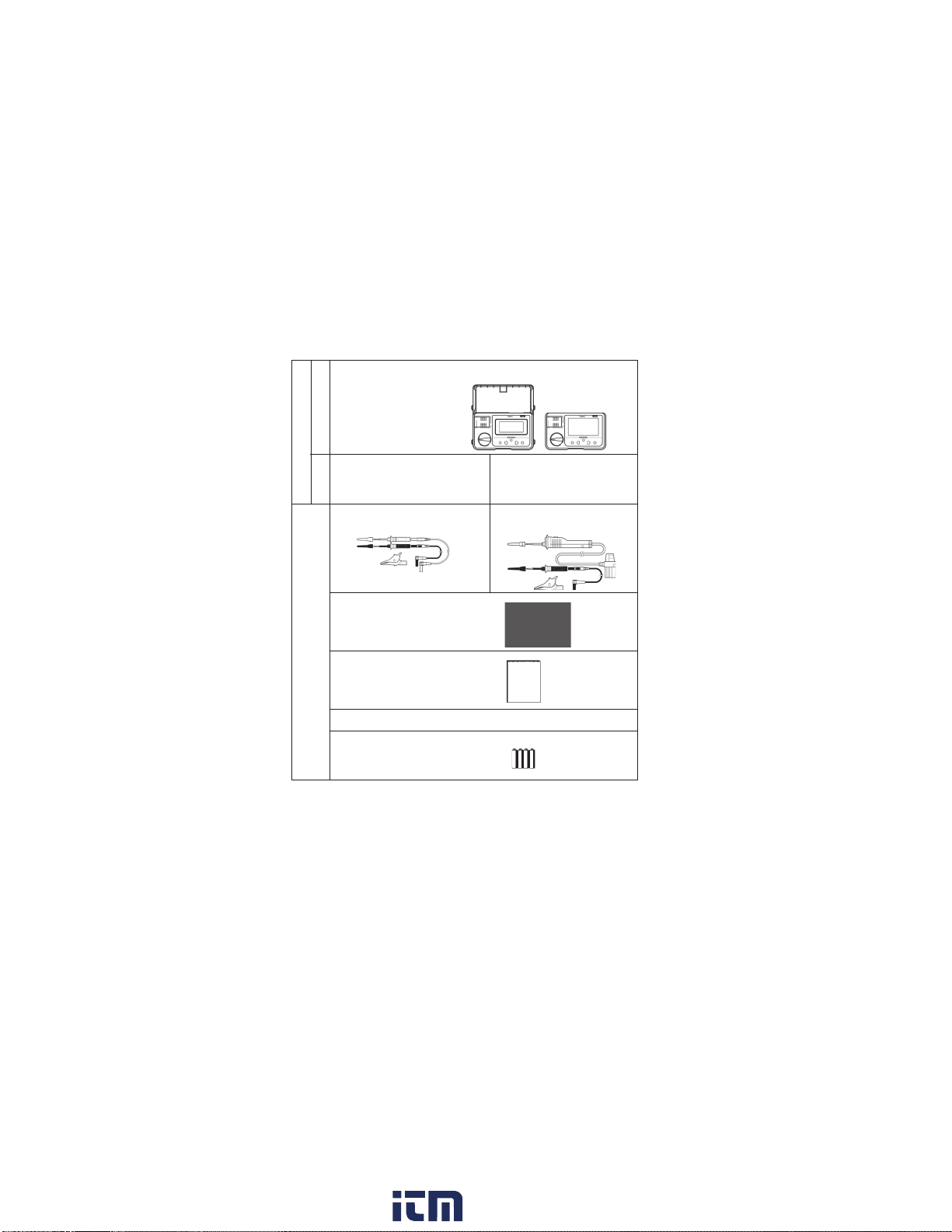
Verifying Package Contents
Package Contents
* L9787 Test Lead and L9788-11 Test Lead Set with Remote Switch are
all exclusively designed for the HIOKI IR4000 series. Do not use for any
other purpose.
Model
Name
Insulation Tester ×1
Version
-10 -11
Accessories
L9787 Test Lead* ×1 L9788-11 Test Lead Set
with Remote Switch* ×1
C0100 Carrying Case ×1
(Included with the IR4052.)
Instruction manual ×1
Neck strap (Included with the IR4051 and IR4053.) ×1
LR6 alkaline battery ×4
IR4051, IR4053
IR4052
www. .com information@itm.com1.800.561.8187

3
Options
⚝ᒁ
4
3
2
1
7
6
5
10
9
8
The following options are available for the IR4000 series. Ask
your authorized Hioki distributor or reseller when ordering.
Options
9804-02 Magnetic
Adapter
(11 mm Corresponding
standard screw:
M6 Button head screw)
C0100 Carrying Case
Carrying case for the IR4052
ªL9787 Test Lead, L9788-10 Test Lead with Remote Switch (Red) and
L9788-11 Test Lead Set with Remote Switch are all exclusively
designed for the HIOKI IR4000 series. Do not use for any other purpose.
L9788-90 Tip Pin
(Pin length 123 mm
and 65 mm from the tip
has width 2.6 mm.)
L9788-92 Breaker Pin
L9788-11 Test Lead Set
with Remote Switch
L9787-91 Breaker Pin
L9788-10 Test Lead with Remote Switch
(Red) * (1.2 m)
L9787 Test Lead * (1.2 m)
www. .com information@itm.com1.800.561.8187
5
Safety Information
⚝ᒁ
4
3
2
1
7
6
5
10
9
8
This instrument is designed to conform to IEC 61010 Safety
Standards, and has been thoroughly tested for safety prior to
shipment. However, using the instrument in a way not described
in this manual may negate the provided safety features.
Before using the instrument, be certain to carefully read the fol-
lowing safety notes.
Safety Information
Mishandling during use could result in injury or death, as
well as damage to the instrument. Be certain that you
understand the instructions and precautions in the man-
ual before use.
• With regard to the electricity supply, there are risks of
electric shock, heat generation, fire, and arc discharge
due to short circuits. If persons unfamiliar with electric-
ity measuring instrument are to use the instrument,
another person familiar with such instruments must
supervise operations.
•Protective gear
This instrument is measured on a live line. To avoid
electric shock when measuring live lines, wear appro-
priate protective gear, such as insulated rubber gloves,
boots and a safety helmet.
www. .com information@itm.com1.800.561.8187

6
Safety Information
This manual contains information and warnings essential for
safe operation of the instrument and for maintaining it in safe
operating condition. Before using it, be sure to carefully read the
following safety precautions.
The following symbols in this manual indicate the relative impor-
tance of cautions and warnings.
Safety Symbols
In the manual, the symbol indicates particularly
important information that the user should read before
using the instrument.
The symbol printed on the instrument indicates that
the user should refer to a corresponding topic in the
manual (marked with the symbol) before using the
relevant function.
Indicates that dangerous voltage may be present at this
terminal.
Indicates a double-insulated device.
Indicates a grounding terminal.
Indicates DC (Direct Current).
Indicates AC (Alternating Current).
DO NOT USE IN DISTRIBUTION SYSTEMS WITH
VOLTAGES HIGHER THAN AC660V.
Indicates that incorrect operation presents an extreme
hazard that could result in serious injury or death to the
user.
Indicates that incorrect operation presents a significant
hazard that could result in serious injury or death to the
user.
Indicates that incorrect operation presents a possibility
of injury to the user or damage to the instrument.
Indicates advisory items related to performance or
correct operation of the instrument.
www. .com information@itm.com1.800.561.8187

7
Safety Information
⚝ᒁ
4
3
2
1
7
6
5
10
9
8
Symbols for Various Standards
Indicates that the product conforms to regulations set out by
the EU Directive.
WEEE marking:
This symbol indicates that the electrical and electronic
appliance is put on the EU market after August 13, 2005, and
producers of the Member States are required to display it on
the appliance under Article 11.2 of Directive 2002/96/EC
(WEEE).
Other Symbols
Indicates a prohibited action.
(p. ) Indicates the location of reference information.
*Indicates that descriptive information is provided below.
Indicates a function of the IR4051 Insulation Tester.
Indicates a function of the IR4052 Insulation Tester.
Indicates a function of the IR4053 Insulation Tester.
IR4051
IR4052
IR4053
The screen of this instrument displays characters in the following manner.
www. .com information@itm.com1.800.561.8187
8
Safety Information
We define measurement tolerances in terms of rdg. (reading)
and dgt. (digit) values, with the following meanings:
rdg. (reading or displayed value)
The value currently being measured and indicated on the
measuring instrument.
rdg. (reading or displayed value)
The smallest displayable unit on a digital measuring instrument,
i.e., the input value that causes the digital display to show a “1”
as the least-significant digit.
This instrument complies with CAT III safety requirements.
To ensure safe operation of measurement instruments, IEC 61010
establishes safety standards for various electrical environments,
categorized as CAT II to CAT IV, and called measurement categories.
Using a measurement
instrument in an
environment designated
with a higher-numbered
category than that for
which the instrument is
rated could result in a
severeaccident,andmust
be carefully avoided.
Use of a measurement
instrument that is not
CAT-rated in CAT II to CAT IVmeasurement applications could result in a
severe accident, and must be carefully avoided.
Accuracy
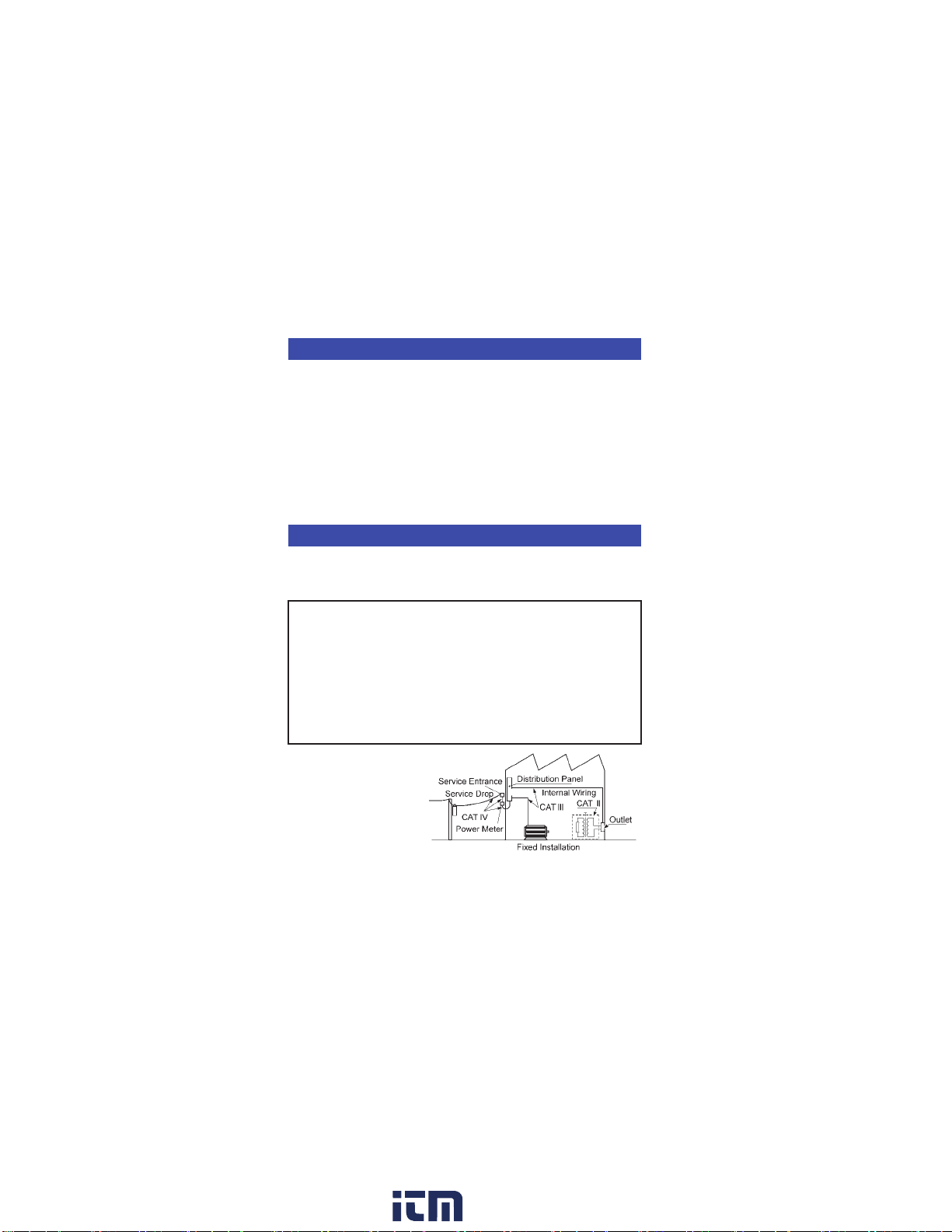
Measurement categories
CAT II:
Primary electrical circuits in equipment connected to an AC
electrical outlet by a power cord (portable tools, household
appliances, etc.)
CAT II covers directly measuring electrical outlet
receptacles.
CAT III: Primary electrical circuits of heavy equipment (fixed
installations) connected directly to the distribution panel,
and feeders from the distribution panel to outlets.
CAT IV: The circuit from the service drop to the service entrance,
and to the power meter and primary overcurrent protection
device (distribution panel).
www. .com information@itm.com1.800.561.8187
This manual suits for next models
3
Table of contents


