HIKOKI CG24EBSP User manual
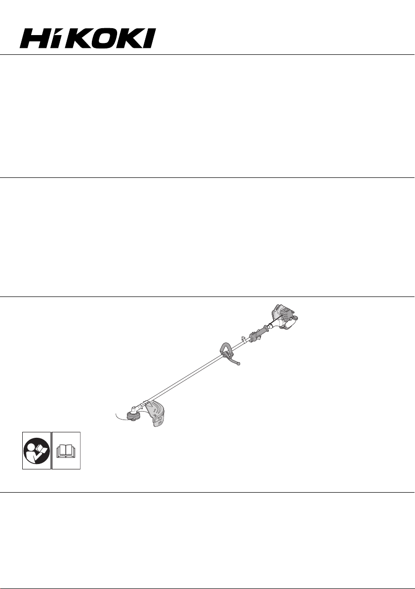
Grass Trimmer/Brush Cutter
Rasentrimmer/Motorsense
Coupe- Herbes/Débroussailleuse
Bordatore/Decespugliatore
Motor Zeis/Motor bosmaaier
Motoguadañas/Desbrozadoras
Foice a motor/Roçadora
Read the manual carefully before operating this machine.
Lesen Sie vor der Verwendung diese Anleitung sorgfältig durch.
Lire attentivement le manuel avant d’utiliser la machine.
Leggere attentamente il manuale prima di mettere in funzione questa apparecchiatura.
Lees de handleiding zorgvuldig door voordat u de machine bedient.
Antes de utilizar esta máquina, lea cuidadosamente el manual.
Leia o manual atentamente antes de operar esta máquina.
Handling instructions
Bedienungsanleitung
Mode d’emploi
Istruzioni per l’uso
CG24EBSP (SL)
Gebruiksaanwijzing
Instrucciones de manejo
Instruções de uso
CG 24EBSP (SL) / CG 24EBSP (S) / CG 24EBS (SL)
CG 24EBS (S) / CG 24EBDP (SL) / CG 24EBDP (SLN)
CG 24EBD (SL) / CG 24EBD (SLN) / CG 27EBSP (SL)
CG 27EBSP (S) / CG 27EBS (SL) / CG 27EBS (S)
CG 27EBDP (SL) / CG 27EBDP (SLN) / CG 27EBD (SL)
CG 27EBD (SLN)
000BookCG24EBSP(SL)WE.indb1000BookCG24EBSP(SL)WE.indb1 2019/01/1515:52:172019/01/1515:52:17

2
12
345
678
91011
3
5
4
6
9
15
13
16
12
11
10
14
7
8
1
2
17
7
000BookCG24EBSP(SL)WE.indb2000BookCG24EBSP(SL)WE.indb2 2019/01/1515:52:172019/01/1515:52:17

3
12 13 14
15 16
17 18 19
20 21 22
23
21
22
20
1918
20
24
25
A
B
27
000BookCG24EBSP(SL)WE.indb3000BookCG24EBSP(SL)WE.indb3 2019/01/1515:52:172019/01/1515:52:17

4
15 m
24
T
28
0.6 mm
29
30
10 cm
23 24 25
26 27 28
29 30 31
32 33 34
000BookCG24EBSP(SL)WE.indb4000BookCG24EBSP(SL)WE.indb4 2019/01/1515:52:172019/01/1515:52:17

5
31
10 cm
31
10 cm
32
34
33
35
11–14 cm 11–14 cm
35 36 37
38 39
000BookCG24EBSP(SL)WE.indb5000BookCG24EBSP(SL)WE.indb5 2019/01/1515:52:172019/01/1515:52:17

6
English (Original instructions)
MEANINGS OF SYMBOLS
NOTE: Some units do not carry them.
Symbols
WARNING
The following show symbols used for the machine. Be sure that you understand their meaning before use.
It is important that you read, fully
understand and observe the following
safety precautions and warnings. Careless
or improper use of the unit may cause
serious or fatal injury.
Ignition stop
Read, understand and follow all warnings
and instructions in this manual and on
the unit.
Fuel and oil mixture
Always wear eye, head and ear protectors
when using this unit. Idle speed adjustment
Do not use metal/rigid blades when this
sign is shown on the unit. Priming pump
Keep all children, bystanders and helpers
15 m away from the unit. If anyone
approaches you, stop the engine and
cutting attachment immediately.
4
Guaranteed Sound power level
Be careful of thrown objects. Hot Surface –Contact with hot surface
can cause serious burns.
min-1
Shows maximum shaft speed. Do not use
the cutting attachment whose max rpm is
below the shaft rpm.
The hedge trimmer attachment cannot
be used on models with this label.
Gloves should be worn when necessary,
e.g., when assembling cutting equipment.
Blade thrust may occur when the
spinning blade contacts a solid object
in the critical area. A dangerous
reaction may occur causing the entire
unit and operator to be thrust violently.
This reaction is called blade thrust. As
a result, the operator may lose control
of the unit which may cause serious or
fatal injury. Blade thrust is more likely
to occur in areas where it is difficult to
see the material to be cut.
Use anti-slip and sturdy footwear.
Choke - Run position (Open)
Choke - Start position (Closed) Indicate handle location. Arrows which
show limits for handle positioning.
Before using your machine
• Read the manual carefully.
• Check that the cutting equipment is correctly assembled and adjusted.
• Start the unit and check the carburetor adjustment. See “MAINTENANCE”.
Contents
WHAT IS WHAT .................................................................................7
WARNINGS AND SAFETY INSTRUCTIONS ...................................8
SPECIFICATIONS .............................................................................9
ASSEMBLY PROCEDURES............................................................10
OPERATING PROCEDURES..........................................................11
MAINTENANCE...............................................................................12
TROUBLESHOOTING.....................................................................15
000BookCG24EBSP(SL)WE.indb6000BookCG24EBSP(SL)WE.indb6 2019/01/1515:52:172019/01/1515:52:17

7
English
10 10
13
8
6
2
5
4
17
13
12
24
23
3
13
119
8
11
9
15
2
14
911
7
15
14 6
2
29
11
13
8
7
6
514
4
19
18
20
5
22
22
22
CG24EBSP (S)
CG24EBS (S)
CG27EBSP (S)
CG27EBS (S)
CG24EBSP (SL)
CG24EBS (SL)
CG27EBSP (SL)
CG27EBS (SL)
7
5
4CG24EBDP (SL)
CG24EBD (SL)
CG27EBDP (SL)
CG27EBD (SL)
8
7
CG24EBDP (SLN)
CG24EBD (SLN)
CG27EBDP (SLN)
CG27EBD (SLN)
1
16
21
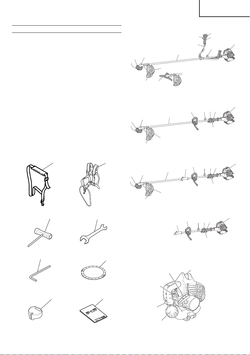
WHAT IS WHAT
Since this manual covers several models, there may be some
difference between pictures and your unit. Use the instructions that
apply to your unit.
1. Fuel cap
2. Throttle trigger
3. Starter handle
4. Cutting attachment guard
5. Cutting attachment
6. Drive shaft tube
7. Handle
8. Suspension eyelet
9. Ignition switch
10. Harness
11. Throttle trigger lockout
12. Choke lever
13. Engine
14. Angle transmission
15. Joint case
16. Combi box spanner
17. Spanner (if so equipped)
18. Hex bar wrench
19. Blade cover (if so equipped)
20. Swivel cap
21. Handling instructions
22. Guard extension
23. Spark plug
24. Priming bulb
000BookCG24EBSP(SL)WE.indb7000BookCG24EBSP(SL)WE.indb7 2019/01/1515:52:182019/01/1515:52:18

8
English
WARNINGS AND SAFETY INSTRUCTIONS
Operator safety
○Always wear a safety face shield or goggles.
○Always wear heavy, long pants and non-slip boots and gloves.
Do not wear loose clothing, jewelry, short pants, sandals or go
barefoot. Secure hair so it is above shoulder length.
○Do not operate this tool when you are tired, ill or under the
influence of alcohol, drugs or medication.
○Do not operate the tool at night or under bad weather conditions
when visibility is poor. And do not operate the tool when it is
raining or right after it has been raining.
Working on slippery ground could lead to an accident if you
lose your balance.
○Never let a child or inexperienced person operate the machine.
○Long-term exposure to noise can result in permanent hearing
impairment. Wear approved hearing protection. Pay attention
to your surroundings. Be aware of any bystanders who may be
signaling a problem. Remove safety equipment immediately
upon shutting offengine.
○Wear head protection.
○Never start or run the engine inside a closed room or building.
Breathing exhaust fumes can kill.
○Keep handles free of oil and fuel.
○Keep hands away from cutting equipment.
○Do not grab or hold the unit by the cutting equipment.
○Gloves should be worn when installing or removing the cutting
attachment. Failure to do so may result in injury.
○When the unit is turned off, make sure the cutting attachment
has stopped before the unit is set down.
○When operation is prolonged, take a break from time to time
so that you may avoid possible Hand-Arm Vibration Syndrome
(HAVS) which is caused by vibration.
WARNING
○Antivibration systems do not guarantee that you will not sustain
Hand-Arm Vibration Syndrome or carpal tunnel syndrome.
Therefore, continual and regular users should monitor closely
the condition of their hands and fingers. If any symptoms of the
above appear, seek medical advice immediately.
○If you are using any medical electric/electronic devices such
as a pacemaker, consult your physician as well as the device
manufacturer prior to operating any power equipment.
Unit/machine safety
○Inspect the entire unit/machine before each use. Replace
damaged parts. Check for fuel leaks and make sure all
fasteners are in place and securely tightened.
○Replace parts that are cracked, chipped or damaged in any
way before using the unit/machine. Faulty parts may increase
the risk of accidents and may lead to an injury.
○Make sure the safety guard is properly attached.
○Keep others away when making carburetor adjustments.
○Use only accessories as recommended for this unit/machine by
the manufacturer.
WARNING
○Never modify the unit/machine in any way. Do not use your unit/
machine for any job except that for which it is intended.
○Tampering with the engine voids the EU type approval of this
engine.
○Non-authorized modifications and/or accessories may result in
serious personal injury or the death of the operator or others.
Fuel safety
○Mix and pour fuel outdoors and where there are no sparks or
flames.
○Use a container approved for fuel.
○Do not smoke or allow smoking near fuel or the unit/machine or
while using the unit/machine.
○Wipe up all fuel spills before starting engine.
○Move at least 3 m away from fueling site before starting engine.
○Stop engine before removing fuel cap.
○Empty the fuel tank before storing the unit/machine. It is
recommended that the fuel be emptied after each use. If fuel is
left in the tank, store so fuel will not leak.
○Store unit/machine and fuel in area where fuel vapors cannot
reach sparks or open flames from water heaters, electric
motors or switches, furnaces. etc.
WARNING
Fuel is easy to ignite or get explosion or inhale fumes, so that
pay special attention when handling or filling fuel.
Cutting safety
○Do not cut any material other than grass and brush.
○Inspect the area to be cut before each use. Remove objects
which can be thrown or become entangled.
○For respiratory protection, wear an aerosol protection mask
when cutting the grass after insecticide is scattered.
○Keep others including children, animals, bystanders and
helpers outside the 15 m hazard zone. Stop the engine
immediately if you are approached.
○Always keep the engine on the right side of your body.
○Hold the unit/machine firmly with both hands.
○Keep firm footing and balance. Do not over-reach.
Losing your balance during work may lead to an injury.
○Keep all parts of your body away from the muffler and cutting
attachment when the engine is running.
○Keep cutting attachment below knee level.
○When relocating to a new work area, be sure to shut offthe
machine and ensure that all cutting attachments are stopped.
○Never place the machine on the ground when running.
○Always ensure that the engine is shut offand any cutting
attachments have completely stopped before clearing debris or
removing grass from the cutting attachment.
○Always carry a first-aid kit when operating any power
equipment.
○Never start or run the engine inside a closed room or building
and/or near inflammable liquids. Breathing exhaust fumes can
kill.
○If the tool is operating poorly and produces strange noise or
vibrations, turn offthe engine immediately and ask your dealer
to have it inspected and repaired.
Continued use under these conditions could lead to injury or
tool damage.
○Use in accordance with local laws and regulations.
Maintenance safety
○Maintain the unit/machine according to recommended
procedures.
○Disconnect the spark plug before performing maintenance
except for carburetor adjustments.
○Keep others away when making carburetor adjustments.
○Use only genuine HiKOKI replacement parts as recommended
by the manufacturer.
Transport and storage
○Carry the unit/machine by hand with the engine stopped and
the muffler away from your body.
○Allow the engine to cool, empty the fuel tank before storing or
transporting.
Secure the machine during transport to prevent loss of fuel,
damage or injury.
○Empty the fuel tank before storing the unit/machine. It is
recommended that the fuel be emptied after each use. If fuel is
left in the tank, store so fuel will not leak.
○Store unit/machine out of the reach of children.
○Clean and maintain the unit carefully and store it in a dry place.
○Make sure engine switch is offwhen transporting or storing.
○When transporting and storing, cover blade with blade cover.
○You have to secure the machine during transport to prevent
loss of fuel, damage or injury.
If situations occur which are not covered in this manual, take care
and use common sense. Contact HiKOKI Authorized Service
Centers if you need assistance. Pay special attention to statements
preceded by the following words:
WARNING
Indicates a strong possibility of severe personal injury or loss of
life, if instructions are not followed.
000BookCG24EBSP(SL)WE.indb8000BookCG24EBSP(SL)WE.indb8 2019/01/1515:52:182019/01/1515:52:18

9
English
CAUTION
Indicates a possibility of personal injury or equipment damage,
if instructions are not followed.
NOTE
Helpful information for correct function and use.
SPECIFICATIONS
Model CG24EBSP / CG24EBS CG24EBDP / CG24EBD
(SL) (S) (SL) (SLN)
Engine
Displacement (cm3)
Spark plug
Idling speed (min-1)
Speed of output shaft (min-1)
Max. engine output (kW)
23.9
NGK BMR7A
2800 –3200
7600
0.8
23.9
NGK BMR7A
2800 –3200
7600
0.8
23.9
NGK BMR7A
2800 –3200
7600
0.8
23.9
NGK BMR7A
2800 –3200
7600
0.8
Fuel tank capacity (cm3)520
Dry weight (kg) 5.0 5.2 5.3 4.4
Cutting attachment Type / Dia. (mm) Nylon cord Nylon cord Metal blade
(255) Nylon co rd ------
Sound pressure
level LpA
(dB (A))
(ISO22868)
Equivalent*
Uncertainty
99
3
99
3
96
3
99
3
99
3
Measured sound
power level LwA (dB (A))
Guaranteed sound
power level LwA (dB (A))
(2000/14/EC)
Racing
(2000/14/EC)
Racing
108
111
108
111
105
108
108
111
------
------
Vibration level (m/s2) (ISO22867)
Equivalent (Front / Left handle)*
Equivalent (Rear / Right handle)*
Uncertainty
5.6
4.0
2.0
3.9
2.7
1.2
3.1
2.8
1.2
6.2
3.4
2.0
------
------
------
CAUTION
Do not disassemble the recoil starter. You may get a possibility
of personal injury with recoil spring.
000BookCG24EBSP(SL)WE.indb9000BookCG24EBSP(SL)WE.indb9 2019/01/1515:52:182019/01/1515:52:18

10
English
ASSEMBLY PROCEDURES
Drive shaft to engine (Fig. 1)
Loosen tube locking bolt (1) about ten turns so that the bolt point will
not obstruct drive shaft tube to be inserted. When inserting drive
shaft tube, hold the tube locking bolt outward preventing inside
fitting from obstructing as well.
Insert the drive shaft into the clutch case of the engine properly until
the marked position (2) on the drive shaft tube meets the clutch
case.
Some models may come with the drive shaft already installed.
NOTE
When it is hard to insert drive shaft up to the marked position on
the drive shaft tube, turn drive shaft by the cutter mounting end
clockwise or counter-clockwise. Tighten tube locking bolt lining
up the hole in the shaft tube. Then tighten clamp bolt securely.
Installation of attachment (EBDP / EBD model only)
1. Join the attachment in place of it.
2. Make sure the lock pin (3) fits in the location hole (4) of tube and
that the tube will not come off. (Fig. 2)
3. Tighten the knob nut (5) securely. (Fig. 2)
Model CG27EBSP / CG27EBS CG27EBDP / CG27EBD
(SL) (S) (SL) (SLN)
Engine
Displacement (cm3)
Spark plug
Idling speed (min-1)
Speed of output shaft (min-1)
Max. engine output (kW)
26.9
NGK BMR7A
2800 –3200
7600
0.9
26.9
NGK BMR7A
2800 –3200
7600
0.9
26.9
NGK BMR7A
2800 –3200
7600
0.9
26.9
NGK BMR7A
2800 –3200
7600
0.9
Fuel tank capacity (cm3)520
Dry weight (kg) 5.2 5.4 5.4 4.5
Cutting attachment Type / Dia. (mm) Nylon cord Nylon cord Metal blade
(255) Nylon co rd ------
Sound pressure
level LpA
(dB (A))
(ISO22868)
Equivalent*
Uncertainty
99
3
99
3
97
3
99
3
99
3
Measured sound
power level LwA (dB (A))
Guaranteed sound
power level LwA (dB (A))
(2000/14/EC)
Racing
(2000/14/EC)
Racing
108
111
108
111
108
111
108
111
------
------
Vibration level (m/s2) (ISO22867)
Equivalent (Front / Left handle)*
Equivalent (Rear / Right handle)*
Uncertainty
6.7
4.1
2.0
4.1
3.0
1.2
3.7
2.6
1.2
5.3
3.4
2.0
------
------
------
NOTE
Equivalent noise level/vibration level are calculated as the time-weighted energy total for noise/vibration levels under various
working conditions with the following time distribution:
* 1/2 Idle, 1/2 racing.
All data subject to change without notice.
Installation of handle
(1) Loop handle type ((SL),(SLN) model)
WARNING
Always use a barrier bar (6) and shoulder harness with the loop
handle. (Fig. 3)
Attach the handle to the drive shaft tube with the angle towards the
engine.
Adjust the location to the most comfortable position before
operation.
NOTE
If your unit has handle location label on drive shaft tube, follow
the illustration.
(2) Bike handle type ((S) model)
Remove the handle bracket (7) from the assembly. (Fig. 4)
Place the handles and attach the handle bracket with four bolts
lightly. Adjust to appropriate position. Then attach it firmly with
the bolts.
Attach the protection tube to the drive shaft or handle using
cord clamps (8). (Fig. 5)
000BookCG24EBSP(SL)WE.indb10000BookCG24EBSP(SL)WE.indb10 2019/01/1515:52:182019/01/1515:52:18

11
English
Throttle wire / stop cord
Press the upper tab (9) and open the air cleaner cover. (Fig. 6)
Connect stop cords. (Fig. 7)
If the throttle outer end (10) is threaded on your unit, screw it and the
earth terminal (11) (if so equipped) into the cable adjuster stay (12)
all the way, and then tighten this cable end using the adjuster nut
(13) against the cable adjuster stay (12).
Connect throttle wire end (14) to carburetor (15) and install swivel
cap (16) (if so equipped) where is included in tool bag, onto swivel
(15) (Fig. 8).
Press the upper tab (9) and close the air cleaner cover. (Fig. 6)
Store stop cords (17) into the air cleaner cover. (Fig. 9)
Some models may come with the parts installed.
Installation of cutting attachment guard (Fig. 10 – 12)
NOTE
The guard bracket may come already mounted to the gear case
on some models.
Install the cutting attachment guard on drive shaft tube against
angle transmission. Tighten the guard bracket firmly so that the
cutting attachment guard does not swing or move down during
operation.
Install the cutting attachment guard to the guard bracket, which also
secures the guard to the gear case using the two guard mounting
screws.
WARNING
If an incorrect or faulty guard is fitted, this may cause serious
personal injury.
CAUTION
Some cutting attachment guards are equipped with sharp line
limiters. Be careful with handling it.
When using a trimmer head with two piece type cutting attachment
guard, attach the guard extension to the cutting attachment guard.
(Fig. 11)
NOTE
○When attaching the guard extension to the cutting attachment
guard, the sharp line limiter must be removed from the cutting
attachment guard, (if so installed).
○To remove the guard extension, refer to the drawings. Wear
gloves as the extension has a sharp line limiter, then push the
three square tabs on the guard one by one in order. (Fig. 12)
Installation of cutting attachment
WARNING
Install the cutting attachment properly and securely as
instructed in the handling instructions.
If not attached properly or securely, it may come offand cause
serious and/or fatal injury.
Installation of semi-auto cutting head
1. Function
Automatically feeds more nylon cutting line when it is tapped at
low rpm (not greater than 4500 min-1).
Specifications
Code No. Type of
attaching screw
Direction of
rotation
Size of
attaching screw
6696454 Female screw Counterclockwise M10×P1.25-LH
6698639
Applicable nylon cord
Cord diameter: Φ2.4 mm Length: 4 m
2. Precautions
○The case must be securely attached to the cover.
○Check the cover, case and other components for cracks or
other damage.
○Check the case and button for wear.
If the wear limit mark (18) on the case is no longer visible or
there is a hole in the bottom (19) of the button, change the new
parts immediately. (Fig. 13)
○The cutting head must be securely mounted to the unit’s gear
case.
○For outstanding performance and reliability, always use HiKOKI
nylon cutting line. Never use wire or other materials that could
become a dangerous projectile.
○If the cutting head does not feed cutting line properly, check
that the nylon line and all components are properly installed.
Contact HiKOKI Authorized Service Centers if you need
assistance.
3. Installation (Fig. 14)
○Install cutting head on gear case of grass trimmers/brush
cutters. The mounting nut is left-hand-threaded. Turn clockwise
to loosen/counterclockwise to tighten.
NOTE
○Since the cutter holder cap is not used here, keep it for when a
metal blade is used, if so equipped.
○Press the stopper pin (20) of the gear case in order to lock the
cutter holder.
4. Adjusting line length
○Set the engine speed as low as possible and tap the head on
the ground. The nylon line will be drawn out about 3 cm with
each tap. (Fig. 15)
Also, you can extend the nylon line by hand but the engine must
be completely stopped. (Fig. 16)
○Adjust the nylon line to the proper length of 11–14 cm before
each operation.
Installation of cutting blade (Fig. 17)
(If so equipped)
When installing a cutting blade, make sure that there are no cracks
or any damage in it and that the cutting edges are facing the correct
direction.
NOTE
○When installing cutter holder cap (21), be sure to set concave
side upward.
○Press the stopper pin (20) of the angle transmission in order
to lock the cutter holder (22). Please note that the cutter fixing
bolt or nut (23) has left-handed threads, (clockwise to loosen/
counter-clockwise to tighten). Tighten the fixing bolt or nut with
the box wrench. [Tightening torque : 12 ―16 N∙m]
CAUTION
○Before operation, make sure the blade has been properly
installed.
○If your unit is equipped with protection cover under a cutting
blade, check it for wear or cracks before operation. If any
damage or wear is found, replace it, as it is an article of
consumption.
○You have to wear gloves when handling the cutting blade.
WARNING
For HiKOKI heads, use only flexible, non-metallic line
recommended by the manufacturer. Never use wire or wire
ropes. They can break offand become a dangerous projectile.
OPERATING PROCEDURES
Fuel (Fig. 18)
WARNING
○The trimmer is equipped with a two-stroke engine. Always run
the engine on fuel, which is mixed with oil.
Provide good ventilation, when fueling or handling fuel.
000BookCG24EBSP(SL)WE.indb11000BookCG24EBSP(SL)WE.indb11 2019/01/1515:52:182019/01/1515:52:18

12
English
○Wear the harness as shown in the figure (if so equipped). The
blade turns counter-clockwise, therefore, be advised to operate
the unit from right to left for efficient cutting. Keep onlookers out
of working area at least 15 m.
○Use in accordance with local laws and regulations.
NOTE
Press the quick release button or pull emergency release flap
(If so equipped) in the event of emergency. (Fig. 25)
WARNING
If cutting attachment should strike against stones or other
debris, stop the engine and make sure that the attachment and
related parts are undamaged. When grass or vines wrap around
attachment, stop engine and attachment and remove them.
Stopping (Fig. 27)
Decrease engine speed and run at an idle for a few minutes, then
turn offignition switch (24).
WARNING
A cutting attachment can injure while it continues to spin after
the engine is stopped or power control is released. When the
unit is turned off, make sure the cutting attachment has stopped
before the unit is set down.
Semi-auto cutting head
○When cutting, operate engine at over 6500 min-1. Extended
time of use at low rpm may wear out the clutch prematurely.
○Cut grass from right to left.
WARNING
A cutting attachment can injure while it continues to spin after
the engine is stopped or power control is released. When the
unit is turned off, make sure the cutting attachment has stopped
before the unit is set down.
Automatically feeds more nylon cutting line when it is tapped at low
rpm (not greater than 4500 min-1).
MAINTENANCE
MAINTENANCE, REPLACEMENT OR REPAIR OF THE EMISSION
CONTROL DEVICES AND SYSTEMS MAY BE PERFORMED
BY ANY NON-ROAD ENGINE REPAIR ESTABLISHMENT OR
INDIVIDUAL.
Carburetor adjustment (Fig. 28)
WARNING
○The cutting attachment may be spinning during carburetor
adjustments.
○Never start the engine without the complete clutch cover and
tube assembled! Otherwise the clutch can come loose and
cause personal injuries.
In the carburetor, fuel is mixed with air. When the engine is test
run at the factory, the carburetor is basically adjusted. A further
adjustment may be required, according to climate and altitude. The
carburetor has one adjustment possibility:
T = Idle speed adjustment screw.
Idle speed adjustment (T)
Check that the air filter is clean. When the idle speed is correct, the
cutting attachment will not rotate. If adjustment is required, close
(clockwise) the T-screw, with the engine running, until the cutting
attachment starts to rotate. Open (counter-clockwise) the screw
until the cutting attachment stops. You have reached the correct idle
speed when the engine runs smoothly in all positions well below the
rpm when the cutting attachment starts to rotate.
If the cutting attachment still rotates after idle speed adjustment,
contact HiKOKI Authorized Service Centers.
NOTE
Standard Idle rpm is 2800 –3200 min-1.
○Fuel contains highly flammable and it is possible to get the
serious personal injury when inhaling or spilling on your body.
Always pay attention when handling fuel. Always have good
ventilation when handling fuel inside building.
Fuel
○Always use branded 89 octane unleaded gasoline.
○Use genuine two-cycle oil or use a mix between 25:1 to 50:1,
please consult the oil bottle for the ratio or HiKOKI Authorized
Service Centers.
○If genuine oil is not available, use an anti-oxidant added quality
oil expressly labeled for air-cooled 2-cycle engine use (JASO
FC GRADE OIL or ISO EGC GRADE). Do not use BIA or TCW
(2-stroke water-cooling type) mixed oil.
○Never use multi-grade oil (10 W/30) or waste oil.
○Always mix fuel and oil in a separate clean container.
Always start by filing half the amount of fuel, which is to be used.
Then add the whole amount of oil. Mix (shake) the fuel mixture. Add
the remaining amount of fuel.
Mix (shake) the fuel-mix thoroughly before filling the fuel tank.
Fueling
WARNING
○Always shut offthe engine before refueling.
○Slowly open the fuel tank, when filling up with fuel, so that
possible over-pressure disappears.
○Tighten the fuel cap carefully, after fueling.
○Always move the trimmer at least 3 m from the fueling area
before starting.
○Always wash any spilled fuel from clothing immediately with
soap.
○Be sure to check for any fuel leakage after refueling.
Before fueling, clean the tank cap area carefully, to ensure that
no dirt falls into the tank. Make sure that the fuel is well mixed by
shaking the container, before fueling.
Starting
CAUTION
Before starting, make sure the cutting attachment does not
touch anything.
1. Set ignition switch (24) to forward away from stop position.
(Fig. 19)
* Push priming bulb (25) about ten times so that fuel flows into
carburetor. (Fig. 20)
2. Set choke lever (27) to START position (closed) (A) (Fig. 21)
3. Pull recoil starter briskly, taking care to keep the handle in your
grasp and not allowing it to snap back. (Fig. 22)
4. When you hear the engine want to start, return choke lever to
RUN position (open) (B). Then pull recoil starter briskly again.
NOTE
If engine does not start, repeat procedures from 2 to 4.
5. Then allow the engine about 2–3 minutes to warm up before
subjecting it to any load.
6. Check that the cutting attachment does not rotate when the
engine is idling.
Cutting (Fig. 23 – 26)
○When cutting, operate engine at over 6500 min-1. Extended
time of use at low rpm may wear out the clutch prematurely.
○Cut grass from right to left.
○Blade thrust may occur when the spinning blade contacts a
solid object in the critical area.
A dangerous reaction may occur causing the entire unit and
operator to be thrust violently. This reaction is called blade
thrust. As a result, the operator may lose control of the unit
which may cause serious or fatal injury. Blade thrust is more
likely to occur in areas where it is difficult to see the material to
be cut.
000BookCG24EBSP(SL)WE.indb12000BookCG24EBSP(SL)WE.indb12 2019/01/1515:52:182019/01/1515:52:18

13
English
WARNING
When the engine is idling the cutting attachment must under no
circumstances rotate.
Air filter (Fig. 29)
The air filter must be cleaned from dust and dirt in order to avoid:
○Carburetor malfunctions
○Starting problems
○Engine power reduction
○Unnecessary wear on the engine parts
○Abnormal fuel consumption
Clean the air filter daily or more often if working in exceptionally
dusty areas.
Cleaning the air filter
Open the air filter cover and the filter (28). Rinse it in warm soap
suds. Check that the filter is dry before reassembly. An air filter
that has been used for some time cannot be cleaned completely.
Therefore, it must regularly be replaced with a new one. A damaged
filter must always be replaced.
Fuel filter (Fig. 30)
Drain all fuel from fuel tank and pull fuel filter line from tank. Pull
filter element out of holder assembly and rinse element in warm
water with detergent.
Rinse thoroughly until all traces of detergent are eliminated.
Squeeze, do not wring, away excess water and allow element to air
dry.
NOTE
If element is hard due to excessive dirt buildup, replace it.
Spark plug (Fig. 31)
The spark plug condition is influenced by:
○An incorrect carburetor setting
○Wrong fuel mixture (too much oil in the gasoline)
○A dirty air filter
○Hard running conditions (such as cold weather)
These factors cause deposits on the spark plug electrodes, which
may result in malfunction and starting difficulties. If the engine
is low on power, difficult to start or runs poorly at idling speed,
always check the spark plug first. If the spark plug is dirty, clean it
and check the electrode gap. Re-adjust if necessary. The correct
gap is 0.6 mm. The spark plug should be replaced after about 100
operation hours or earlier if the electrodes are badly eroded.
NOTE
In some areas, local law requires using a resistor spark plug
to suppress ignition signals. If this machine was originally
equipped with resistor spark plug, use same type of spark plug
for replacement.
Angle transmission (Fig. 32)
Check angle transmission or angle gear for grease level about every
50 hours of operation by removing the grease filler plug on the side
of angle transmission.
If no grease can be seen on the flanks of the gears, fill the
transmission with quality lithium based multipurpose grease up to
3/4. Do not completely fill the transmission.
Semi-auto cutting head
Nylon line replacement
(1) Remove the case (29) by firmly pushing inward the locking tabs
with your thumbs as shown in Fig. 33.
(2) After removing the case, take out the reel and discard the
remaining line.
(3) Fold the new nylon line unevenly in half as shown in picture.
Hook the U-shaped end of the nylon line into the groove (30) on
the center partition of the reel.
One side of the cord should be about 10 cm longer than the
other side.
Wind both halves of the line on the reel in the same direction,
keeping each half of the line on its own side of the partition.
(Fig. 34)
(4) Push each line into the stopper holes (31), leaving the loose
ends approx. 10 cm in length. (Fig. 35)
(5) Insert both loose ends of the line through the cord guide (32)
when placing the reel in the case. (Fig. 36)
NOTE
When placing a reel in the case, try to line up the stopper holes
(31) with the cord guide (32) for easier line release later.
(6) Place the cover over the case so that the cap locking tabs (33)
on the case meet the long holes (34) on the cover. Then push
the case securely until it clicks into place. (Fig. 37)
(7) The initial cutting line length should be approx. 11–14 cm and
should be equal on both sides. (Fig. 38)
Blade (Fig. 39)
WARNING
Wear protective gloves when handling or performing
maintenance on the blade.
○Use a sharp blade. A dull blade is more likely to snag and
thrust. Replace the fastening nut if it is damaged and hard to
tighten.
○When replacing blade, purchase one recommended by
HiKOKI, with a 25.4 mm (one inch) fitting hole.
○In the case of a 3 tooth blade (35), it can be used on either side.
○Use the correct blade for the type of work.
○When replacing blades, use appropriate tools.
○When cutting edges become dull, re-sharpen or file as shown
in the illustration. Incorrect sharpening may cause excessive
vibration.
○Discard blades that are bent, warped, cracked, broken or
damaged in any way.
NOTE
When sharpening blade it is important to maintain an original
shape of radius at the base of the tooth to avoid cracking.
Maintenance schedule
Below you will find some general maintenance instructions. For
further information please contact HiKOKI Authorized Service
Centers.
Daily maintenance
○Clean the exterior of the unit.
○Check that the harness is undamaged.
○Check the cutting attachment guard for damage or cracks.
Change the guard in case of impacts or cracks.
○Check that the cutting attachment is properly centred, sharp,
and without cracks. An off-centre cutting attachment induces
heavy vibrations that may damage the unit.
○Check that the cutting attachment nut is sufficiently tightened.
○Make sure that the blade transport guard is undamaged and
that it can be securely fitted.
○Check that nuts and screws are sufficiently tightened.
○Check that the unit is undamaged and free of defects.
Weekly maintenance
○Check the starter, especially the cord and return spring.
○Clean the exterior of the spark plug.
○Remove it and check the electrode gap. Adjust it to 0.6 mm, or
change the spark plug.
○Check that the angle gear is filled with grease up to 3/4.
○Clean the air filter.
Monthly maintenance
○Rinse the fuel tank with gasoline.
○Clean the exterior of the carburetor and the space around it.
○Clean the fan and the space around it.
000BookCG24EBSP(SL)WE.indb13000BookCG24EBSP(SL)WE.indb13 2019/01/1515:52:182019/01/1515:52:18

14
English
List of recommended accessories
Type Name
Specification LOOP HANDLE BIKE HANDLE MULTI PURPOSE
Diameter
Feed System Adapter or
No. of Teeth (Blade)
Blade Thickness (mm)
or
Trimmer line Diameter (mm)
CG24EBSP (SL)
CG24EBS (SL)
CG27EBSP (SL)
CG27EBS (SL)
CG24EBSP (S)
CG24EBS (S)
CG27EBSP (S)
CG27EBS (S)
CG24EBDP (SL)
CG24EBD (SL)
CG27EBDP (SL)
CG27EBD (SL)
ALUMINUM HEADS
NYLON HEAD
CH-100
(W/NYLON LINE) 4” Pre-Cut Line 2.2 –3.0
●●●●●●
NYLON HEAD
CH-100 ●●●●●●
NYLON HEAD
CH-300
(W/CUTTER
HOLDER CAP) 5” Manual line
feed 2.2 –2.7
●●●
NYLON HEAD
CH-300 ●●●
TAP & GO NYLON
HEADS
NYLON HEAD
BF-5 5”
L M10 x 1.25
Nut
L M8 x 1.25
2.2 –3.0 ●●●●●●
BLADES
BLADE
B3/10/2.0 10” 3 2.0 ●
BLADE
B3/12/3.0 12” 3 3.0 ●
BLADE
B4/9/1.6 9” 4 1.6 ●●
BLADE
B4/10/1.6 10” 4 1.6 ●●
000BookCG24EBSP(SL)WE.indb14000BookCG24EBSP(SL)WE.indb14 2019/01/1515:52:182019/01/1515:52:18

15
English
TROUBLESHOOTING
Use the inspections in the table below if the tool does not operate
normally. If this does not remedy the problem, consult your dealer
or the HiKOKI Authorized Service Center.
Condition Cause Remedy
Engine does not start
Fuel system
Fuel tank is empty or fuel level is low Fill the fuel tank with the correct fuel mix (25:1-
50:1)
Fuel tank contains old fuel (offensive odor) Replace with new fuel
Too much fuel is absorbed and spark plug
is wet
1.Disconnect the spark plug and allow to dry
2.Pull the starter handle 5 or 6 times to remove
the surplus fuel
3.Attach the spark plug
4.Set the choke lever to RUN position and pull the
starter handle
Fuel filter is clogged with dirt Clean the fuel filter
Fuel pipe is bent or disconnected Ensure that the fuel flows smoothly
Carburetor malfunction Contact HiKOKI Authorized Service Centers
Electrical
system
Stop switch lead has short-circuited Contact HiKOKI Authorized Service Centers
Spark plug is dirty Replace or clean the spark plug
Electrode gap is too big Adjust the gap to 0.6mm
Poor connection between high tension cable
and spark plug Reconnect
Electrical system malfunction Contact HiKOKI Authorized Service Centers
Other Muffler exhaust port is clogged with carbon Contact HiKOKI Authorized Service Centers for
repair
Engine starts but cuts
out straightaway
Engine is apt to
cut out
Fuel system
Fuel tank is empty or fuel level is low Fill the fuel tank with the correct fuel mix (25:1-
50:1)
Fuel tank contains old fuel (offensive odor) Replace with new fuel
Two-cycle oil has not been added Contact HiKOKI Authorized Service Centers
Choke lever is in START position Set the choke lever to RUN position
Air has got into fuel system Reconnect the fuel pipe or joint
Carburetor malfunction Contact HiKOKI Authorized Service Centers
Electrical
system
Ignition failure
Spark plug failure Replace with new spark plug
Electrical system failure Contact HiKOKI Authorized Service Centers
Other
Engine overheating
Wrong spark plug model Replace with designated part
See “SPECIFICATIONS”
Dirty air cleaner Clean
Carbon clogging (muffler exhaust port) Clean
Insufficient compression (piston, piston ring,
cylinder) Contact HiKOKI Authorized Service Centers
Abnormal vibration
Cutting attachment is not properly installed See “Installation of cutting attachment”
Handle, handle bracket or other fastening
part is loose Check and tighten
Blade is bent or damaged Replace with new blade
Grass is wrapped round gear case Remove grass
Engine is running but blade does
not move
Movement is poor
Grass is wrapped round gear case Remove grass and dirt
Engine does not stop Stop switch failure
Set the choke lever to START position to stop the
engine
Cease use immediately and contact HiKOKI
Authorized Service Centers
Engine stops when throttle is closed Idle speed is too low Contact HiKOKI Authorized Service Centers
Blade continues rotating when
throttle is closed
Idle speed is too high
Throttle wire is too taut Contact HiKOKI Authorized Service Centers
000BookCG24EBSP(SL)WE.indb15000BookCG24EBSP(SL)WE.indb15 2019/01/1515:52:182019/01/1515:52:18

Deutsch
16
(Übersetzung der Original-Gebrauchsanweisung)
SYMBOLBEDEUTUNGEN
HINWEIS: Nicht alle Geräte sind mit diesen Symbolen versehen.
Symbole
WARNUNG
Die folgenden Symbole werden für diese Maschine verwendet. Achten Sie darauf, diese vor der Verwendung
zu verstehen.
Es ist wichtig, dass Sie sich mit den
nachfolgenden Vorsichtsmaßnahmen
und Warnungen vertraut machen und
diese befolgen. Unvorsichtige oder
unsachgemäße Handhabung des Geräts
kann schwere oder tödliche Verletzungen
zur Folge haben.
Zündungsstopp
Lesen, verstehen und befolgen Sie alle
Warnungen und Anweisungen in dieser
Anleitung und am Gerät selbst.
Kraftstoff-Öl-Gemisch
Bei Gebrauch des Geräts immer Gesichts-,
Kopf- und Gehörschutz tragen. Leerlaufdrehzahleinstellung
Wenn dieses Zeichen am Gerät angebracht
ist, keine starren Messer/Metallmesser
verwenden.
Ansaugpumpe
Kinder und Zuschauer in einem Abstand
von 15 m vom Gerät halten. Falls sich
jemand nähert, den Motor und das Zubehör
sofort ausschalten.
4
Garantierter Schallleistungspegel
Auf hochgeschleuderte Gegenstände
achten.
Heiße Oberfläche –Eine Berührung
der heißen Oberfläche kann schwere
Verbrennungen verursachen.
min-1
Zeigt die maximale Drehzahl der Welle
an. Verwenden Sie kein Schneidzubehör,
dessen Maximaldrehzahl unter diesem
Wert liegt.
Das Heckenscheren-Anbauwerkzeug
kann nicht an Modellen mit diesem
Schild verwendet werden.
Handschuhe sind dann zu tragen, wenn
dies notwendig ist, z.B. bei der Montage
der Schneidausrüstung.
Ein Messerstoß ist möglich, wenn das
rotierende Messer im kritischen Bereich mit
einem massiven Gegenstand in Berührung
kommt. In diesem Fall kann es zu einer
gefährlichen Reaktion kommen, bei der
das gesamte Gerät und der Bediener
einem heftigen Stoß ausgesetzt werden.
Diese Reaktion wird als Messerstoß
bezeichnet. Das Resultat ist u.U., dass
der Bediener die Kontrolle über das Gerät
verliert und schwere oder lebensgefährliche
Verletzungen davonträgt. Messerstöße
sind in Arbeitsbereichen, wo das zu
schneidende Vegetationsmaterial nur
schwer einsehbar ist, wahrscheinlicher.
Rutschfestes Schuhwerk tragen, das guten
Halt bietet.
Choke –Betriebsposition (offen)
Choke –Startposition (geschlossen) Bezeichnet den Griffstangenplatz.
Pfeile, die den Grenzwert für die
Griffposition anzeigen.
Vor dem Gebrauch Ihres Geräts
• Bedienungsanleitung sorgfältig durchlesen.
• Montage und Einstellung der Schneidausrüstung kontrollieren.
• Gerät starten und Vergasereinstellung prüfen. Siehe “WARTUNG”.
Inhalt
TEILEBEZEICHNUNGEN................................................................17
WARN- UND SICHERHEITSHINWEISE.........................................18
TECHNISCHE DATEN.....................................................................19
ZUSAMMENBAU.............................................................................20
BETRIEB..........................................................................................22
WARTUNG.......................................................................................23
FEHLERSUCHE UND -BESEITIGUNG ..........................................26
000BookCG24EBSP(SL)WE.indb16000BookCG24EBSP(SL)WE.indb16 2019/01/1515:52:182019/01/1515:52:18
Deutsch
17
10 10
17
19
18
20
16
21
13
8
6
2
5
4
13
12
24
23
3
13
119
8
11
9
15
2
14
911
7
15
14 6
2
29
11
13
8
7
6
514
4
5
22
22
22
CG24EBSP (S)
CG24EBS (S)
CG27EBSP (S)
CG27EBS (S)
CG24EBSP (SL)
CG24EBS (SL)
CG27EBSP (SL)
CG27EBS (SL)
7
5
4CG24EBDP (SL)
CG24EBD (SL)
CG27EBDP (SL)
CG27EBD (SL)
8
7
CG24EBDP (SLN)
CG24EBD (SLN)
CG27EBDP (SLN)
CG27EBD (SLN)
1
TEILEBEZEICHNUNGEN
Da dieses Handbuch für mehrere Modelle gilt, können die
Abbildungen gegebenenfalls von Ihrem Gerät abweichen.
Verwenden Sie die für Ihr Gerät geltenden Anweisungen.
1. Benzintank
2. Gashebel
3. Startgriff
4. Schneid-Vorsatzschutz
5. Schneid-Vorsatzgerät
6. Antriebswellenrohr
7. Griff
8. Tragegurtöse
9. Zündschalter
10. Tragegurt
11. Gashebelsperre
12. Chokehebel
13. Motor
14. Winkelgetriebe
15. Schäftungsgehäuse
16. Kombischlüssel
17. Spanner (falls vorhanden)
18. Sechskant-Inbusschlüssel
19. Messerschutz (falls vorhanden)
20. Drehkopf
21. Bedienungsanleitung
22. Schutzerweiterung
23. Zündkerze
24. Ansauglampe
000BookCG24EBSP(SL)WE.indb17000BookCG24EBSP(SL)WE.indb17 2019/01/1515:52:182019/01/1515:52:18

Deutsch
18
WARN- UND SICHERHEITSHINWEISE
Bedienersicherheit
○Immer einen Gesichtsschutz bzw. eine Schutzbrille tragen.
○Tragen Sie immer dicke, lange Hosen, rutschfeste Schuhe und
Handschuhe. Das Arbeiten mit lockerer Kleidung, Schmuck,
kurzen Hosen, Sandalen oder barfuß ist zu vermeiden. Das
Haar ist so zu sichern, dass es nicht bis zu den Schultern
herunterhängt.
○Das Gerät darf nicht von Personen bedient werden, die
übermüdet oder krank sind oder unter Alkohol- oder
Medikamenteneinfluss stehen.
○Das Gerät nicht bei Nacht oder schlechten
Witterungsverhältnissen mit eingeschränkter Sicht bedienen.
Das Gerät zudem nicht bei Regen oder kurz nach einem
Regenschauer betätigen.
Arbeit auf rutschigem Untergrund kann zu Unfällen führen,
wenn Sie das Gleichgewicht verlieren.
○Unter keinen Umständen zulassen, dass ein Kind oder eine
unerfahrene Person mit dem Gerät arbeitet.
○Langfristige Aussetzung zu lauten Geräuschen kann
zu bleibenden Hörschäden führen. Tragen Sie einen
zugelassenen Gehörschutz. Die Umgebung im Auge behalten.
Auf Beistehende achten, die unter Umständen ein Problem
signalisieren. Die Schutzbekleidung erst nach Abstellen des
Motors wieder ablegen.
○Kopfschutz tragen.
○Der Motor darf nie innerhalb geschlossener Räume oder
Gebäude gestartet bzw. betrieben werden. Einatmen der
Abgase kann den Tod zur Folge haben.
○Die Griffe frei von Öl und Kraftstoffhalten.
○Hände von den Schneiden fernhalten.
○Das Gerät nicht an der Schneidgarnitur fassen bzw. halten.
○Beim Montieren oder Entfernen des Schneidwerkzeugs
müssen Handschuhe getragen werden.
Nichtbeachtung kann eine Verletzung zur Folge haben.
○Das Gerät nach dem Ausschalten des Motors erst am
Boden abstellen, wenn das Schneidwerkzeug zum Stillstand
gekommen ist.
○Bei Dauereinsatz von Zeit zu Zeit eine Pause einlegen als
vorbeugende Maßnahme gegen die Weißfingerkrankheit, die
durch ständige Vibration verursacht wird.
WARNUNG
○Vibrationsdämpfungssysteme sind kein garantierter Schutz
gegen die Weißfingerkrankheit bzw. das Karpaltunnelsyndrom.
Daher ist bei regelmäßigem Dauereinsatz des Geräts der
Zustand von Fingern und Handwurzel aufmerksam zu
beobachten. Falls Symptome der obengenannten Krankheiten
auftreten, sofort einen Arzt aufsuchen.
○Träger eines medizinischen elektrischen bzw. elektronischen
Geräts (Herzschrittmacher u. dgl.) sollten sich vor dem
Gebrauch eines Motorgeräts von Ihrem Arzt sowie dem
Hersteller des Geräts diesbezüglich beraten lassen.
Geräte-/Maschinensicherheit
○Das Gerät vor jedem Einsatz einer eingehenden Kontrolle
unterziehen. Beschädigte Teile ersetzen. Das Gerät auf
auslaufenden Kraftstoffuntersuchen und sicherstellen, dass
alle Befestigungsteile vorhanden und sicher angezogen sind.
○Gerissene, ausgebrochene oder auf andere Weise
beschädigte Teile sind vor dem Einsatz des Gerätes durch
neue zu ersetzen. Defekte Teile vergrößern das Unfallrisiko
und können eine Verletzung zur Folge haben.
○Es ist darauf zu achten, dass die Schutzvorrichtung
ordnungsgemäß angebracht ist.
○Während der Vergasereinstellung dürfen sich andere Personen
nicht in der Nähe aufhalten.
○Nur das vom Hersteller für dieses Gerät empfohlene Zubehör
darf verwendet werden.
WARNUNG
○Keinesfalls das Gerät in irgendeiner Weise abändern. Das
Gerät nur für die Zwecke verwenden, für die es bestimmt ist.
○Durch Eingriffe am Motor erlischt die EU-Betriebserlaubnis für
diesen Motor.
○Nicht autorisierte Änderungen und/oder Zubehörteile können
eine schwere Körperverletzung oder den Tod des Bedieners
oder Anderer zur Folge haben.
Kraftstoffsicherheit
○Kraftstoffim Freien und von Funken und Feuer entfernt
mischen und einfüllen.
○Einen für Kraftstoffe zugelassenen Behälter verwenden.
○In der Nähe des Kraftstoffs, des Geräts sowie beim Arbeiten mit
dem Gerät ist das Rauchen zu unterlassen.
○Vor dem Starten des Motors muss eventuell verschütteter
Kraftstoffrestlos entfernt werden.
○Zum Starten des Motors das Gerät mindestens 3 m von der
Kraftstoffeinfüllstelle entfernen.
○Vor dem Abnehmen des Tankdeckels den Motor ausschalten.
○Vor der Einlagerung des Geräts den Kraftstofftank leeren. Es
wird empfohlen, den Kraftstoffnach jedem Einsatz abzulassen.
Mit gefülltem Tank ist das Gerät so zu lagern, dass kein
Kraftstoffausläuft.
○Gerät und Kraftstoffan einem Ort lagern, wo Kraftstoffdämpfe
nicht mit Funken oder offenen Flammen von Wassererhitzern,
Elektromotoren oder elektrischen Schaltern, Öfen usw. in
Berührung kommen können.
WARNUNG
Kraftstoffist leicht entflammbar, kann explodieren und schadet
den Atemwegen, weshalb bei der Handhabung von und der
Befüllung mit Kraftstoffentsprechend umsichtig vorzugehen
ist.
Schneidsicherheit
○Das Gerät nur zum Mähen von Gras und zum Schneiden von
Buschwerk und Unterholz einsetzen.
○Vor jedem Gebrauch die zu mähende Fläche inspizieren.
Gegenstände entfernen, die hochgeschleudert werden oder
sich im Mähkopf verfangen könnten.
○Zum Schutz der Atmungsorgane beim Mähen von Gras,
auf dem Insektenvernichtungsmittel versprüht wurde, eine
Aerosolschutzmaske tragen.
○Kinder, Tiere, Umstehende, Helfer usw. dürfen sich nicht
innerhalb der 15 m-Gefahrenzone aufhalten. Den Motor sofort
abstellen, wenn sich jemand nähert.
○Der Motor muss sich immer auf der rechten Körperseite
befinden.
○Gerät fest mit beiden Händen halten.
○Auf sicheren Stand und gutes Gleichgewicht achten. Nicht zu
weit vorbeugen.
Wenn man beim Arbeiten das Gleichgewicht verliert, kann dies
eine Verletzung zur Folge haben.
○Schneidwerkzeug und Schalldämpfer bei laufendem Motor
vom Körper fernhalten.
○Die Schneidgarnitur stets unter Kniehöhe halten.
○Bei Standortwechseln unbedingt den Motor ausschalten und
sicherstellen, dass das Schneidwerkzeug still steht.
○Das Gerät niemals mit laufendem Motor auf dem Boden
abstellen.
○Vor dem Entfernen von Schmutz oder Gras vom
Schneidwerkzeug den Motor ausschalten und sicherstellen,
dass die Kette zum Stillstand gekommen ist.
○Beim Arbeiten mit Motorgeräten stets einen Verbandskasten
mitführen.
○Der Motor darf nie innerhalb geschlossener Räume oder
Gebäude und/oder in der Nähe entflammbarer Flüssigkeiten
gestartet bzw. betrieben werden. Einatmen der Abgase kann
den Tod zur Folge haben.
○Bei schwacher Geräteleistung oder seltsamen Geräuschen
oder Vibrationen des Geräts den Motor sofort abstellen und
das Gerät durch Ihren Fachhändler inspizieren und reparieren
lassen.
Eine weitere Verwendung in diesem Zustand kann zu
Verletzungen oder der Beschädigung des Geräts führen.
○Beim Gebrauch die örtlich gültigen Gesetze und Vorschriften
einhalten.
000BookCG24EBSP(SL)WE.indb18000BookCG24EBSP(SL)WE.indb18 2019/01/1515:52:192019/01/1515:52:19

Deutsch
19
Wartungssicherheit
○Das Gerät vorschriftsmäßig warten.
○Vor Durchführung von Wartungsarbeiten die Zündkerze
entfernen, sofern es sich nicht um eine Vergasereinstellung
handelt.
○Während der Vergasereinstellung dürfen sich andere Personen
nicht in der Nähe aufhalten.
○Nur Original-Ersatzteile von HiKOKI verwenden, wie vom
Hersteller empfohlen.
Transport und Lagerung
○Das Gerät mit ausgeschaltetem Motor tragen und den
Schalldämpfer vom Körper fernhalten.
○Lassen Sie den Motor abkühlen und leeren Sie den
Kraftstofftank, bevor Sie ihn lagern oder transportieren.
Sichern Sie die Maschine während des Transports, um zu
verhindern, dass Kraftstoffverloren geht oder dass Schäden
oder Verletzungen auftreten.
○Vor der Einlagerung des Geräts den Kraftstofftank leeren. Es
wird empfohlen, den Kraftstoffnach jedem Einsatz abzulassen.
Mit gefülltem Tank ist das Gerät so zu lagern, dass kein
Kraftstoffausläuft.
○Das Gerät so lagern, dass es nicht in Kinderhände gerät.
○Das Gerät sorgfältig reinigen und warten, um es dann an einem
trockenen Ort zu lagern.
○Bei Transport oder Lagerung darauf achten, dass der
Zündschalter ausgeschaltet ist.
○Bei Transport und Lagerung den Klingenschutz auf die Klinge
aufsetzen.
○Sie müssen die Maschine beim Transport sichern, um
Auslaufen von Kraftstoff, Schäden, oder Verletzungen zu
verhindern.
In Situationen, die nicht in dieser Anleitung behandelt sind,
entsprechende Vor- und Umsicht walten lassen. Sollten Sie
Hilfe benötigen, wenden Sie sich an einem einer von HiKOKI
autorisierten Service-Werkstatt. Die folgenden Wörter sind
Abschnitten vorangestellt, denen besondere Aufmerksamkeit
gewidmet werden sollte:
WARNUNG
Kennzeichnet Anweisungen, deren Nichtbefolgung eine
schwere Verletzung oder den Tod zur Folge haben kann.
VORSICHT
Kennzeichnet Anweisungen, deren Nichtbefolgung eine
Verletzung oder Sachschaden zur Folge haben kann.
HINWEIS
Kennzeichnet nützliche Informationen für den
vorschriftsmäßigen Gebrauch.
VORSICHT
Den Zugstarter nicht zerlegen. Die Feder der Vorrichtung kann
Verletzungen verursachen.
TECHNISCHE DATEN
Modell CG24EBSP / CG24EBS CG24EBDP / CG24EBD
(SL) (S) (SL) (SLN)
Motor
Hubvolumen (cm3)
Zündkerze
Leerlaufdrehzahl (min-1)
Drehzahl der Ausgangswelle (min-1)
Max. Motorleistung (kW)
23,9
NGK BMR7A
2800 –3200
7600
0,8
23,9
NGK BMR7A
2800 –3200
7600
0,8
23,9
NGK BMR7A
2800 –3200
7600
0,8
23,9
NGK BMR7A
2800 –3200
7600
0,8
Kraftstofftankvolumen (cm3)520
Trockengewicht (kg) 5,0 5,2 5,3 4,4
Schneid-Vorsatzgerät Typ / Durchm.
(mm) Nylonschnur Nylonschnur Metallklinge
(255) Nylons chnur ------
Schalldruckpegel
LpA (dB (A)
(ISO22868)
Äquivalen*
Unsicherheit
99
3
99
3
96
3
99
3
99
3
Gemessener Schallpegel
LwA (dB (A))
Garantierter Schallpegel
LwA (dB (A))
(2000/14/EG)
Volllast
(2000/14/EG)
Volllast
108
111
108
111
105
108
108
111
------
------
Vibrationspegel (m/s2) (ISO22867)
Äquivalent (Vorderer / linker Griff)*
Äquivalent (Hinterer / rechter Griff)*
Unsicherheit
5,6
4,0
2,0
3,9
2,7
1,2
3,1
2,8
1,2
6,2
3,4
2,0
------
------
------
000BookCG24EBSP(SL)WE.indb19000BookCG24EBSP(SL)WE.indb19 2019/01/1515:52:192019/01/1515:52:19

Deutsch
20
Modell CG27EBSP / CG27EBS CG27EBDP / CG27EBD
(SL) (S) (SL) (SLN)
Motor
Hubvolumen (cm3)
Zündkerze
Leerlaufdrehzahl (min-1)
Drehzahl der Ausgangswelle (min-1)
Max. Motorleistung (kW)
26,9
NGK BMR7A
2800 –3200
7600
0,9
26,9
NGK BMR7A
2800 –3200
7600
0,9
26,9
NGK BMR7A
2800 –3200
7600
0,9
26,9
NGK BMR7A
2800 –3200
7600
0,9
Kraftstofftankvolumen (cm3)520
Trockengewicht (kg) 5,2 5,4 5,4 4,5
Schneid-Vorsatzgerät Typ / Durchm.
(mm) Nylonschnur Nylonschnur Metallklinge
(255) Nylons chnur ------
Schalldruckpegel
LpA (dB (A))
(ISO22868)
Äquivalen*
Unsicherheit
99
3
99
3
97
3
99
3
99
3
Gemessener Schallpegel
LwA (dB (A))
Garantierter Schallpegel
LwA (dB (A))
(2000/14/EG)
Volllast
(2000/14/EG)
Volllast
108
111
108
111
108
111
108
111
------
------
Vibrationspegel (m/s2) (ISO22867)
Äquivalent (Vorderer / linker Griff)*
Äquivalent (Hinterer / rechter Griff)*
Unsicherheit
6,7
4,1
2,0
4,1
3,0
1,2
3,7
2,6
1,2
5,3
3,4
2,0
------
------
------
HINWEIS
Die entsprechenden Geräusch-/Vibrationspegel werden als zeitgewichtete Energiesumme für Geräusch-/Vibrationspegel unter
verschiedenen Arbeitsbedingungen mit folgender Zeitaufteilung berechnet:
* 1/2 Leerlauf, 1/2 schnell.
Änderung der technischen Daten jederzeit vorbehalten.
ZUSAMMENBAU
Antriebswelle und Motor (Abb. 1)
Den Rohrblockierungsbolzen (1) um ungefähr zehn
Schraubendrehungen lockern, so dass die Bolzenspitze
das Antriebswellenrohr beim Einschieben nicht behindert.
Halten Sie beim Einschieben des Antriebswellenrohrs den
Rohrblockierungsbolzen so fest, dass Blockierungen durch das
innere Zubehör vermieden werden.
Die Antriebswelle soweit in das Kupplungsgehäuse einschieben,
bis zur Markierung (2) auf dem Antriebswellenrohr am
Kupplungsgehäuse liegt.
Einige Modelle werden mit bereits vormontierter Antriebswelle
geliefert.
HINWEIS
Wenn sich die Antriebswelle nur schwer bis zur
Markierung einschieben lässt, die Antriebswelle am
Schneidvorrichtungsende fassen und beim Einschieben
im oder gegen den Uhrzeigersinn drehen. Den
Blockierungsbolzen so anziehen, dass er in das Loch des
Antriebswellenrohrs eingreift. Dann die Spannschraube fest
anziehen.
Montage der Scheidvorrichtung (nur EBDP / EBD-Modell)
1. Bringen Sie die Schneidvorrichtung an der vorgesehenen Stelle
an.
2. Stellen Sie sicher, dass sich der Spannstift (3) im
Befestigungsloch (4) des Rohrs befindet und das Rohr fest
sitzt. (Abb. 2)
3. Ziehen Sie die Griffmutter (5) fest an. (Abb. 2)
Montage des Handgriffs
(1) Schlaufengriff-Typ ((SL), (SLN) Modell)
WARNUNG
Verwenden Sie stets einen Messerschutz (6) und einen
Tragegurt mit dem Bügelgriff. (Abb. 3)
Den Handgriffzum Motor geneigt an das Antriebswellenrohr
anbringen.
Den Handgriffvor der Inbetriebnahme auf eine komfortable Position
einstellen.
HINWEIS
Falls auf dem Antriebswellenrohr Ihres Geräts ein Schild mit
Informationen zur Handgriffposition angebracht ist, halten Sie
sich an die Darstellung.
000BookCG24EBSP(SL)WE.indb20000BookCG24EBSP(SL)WE.indb20 2019/01/1515:52:192019/01/1515:52:19
Table of contents
Languages:
Other HIKOKI Trimmer manuals

HIKOKI
HIKOKI CG 18DA User manual

HIKOKI
HIKOKI CH 3672DA User manual
 User manual")
HIKOKI
HIKOKI CH 24EA(50ST) User manual

HIKOKI
HIKOKI CG 24ECP User manual

HIKOKI
HIKOKI CH 24EAP User manual

HIKOKI
HIKOKI CG 23EC User manual

HIKOKI
HIKOKI CG 36DB User manual
 User manual")
HIKOKI
HIKOKI CG 24EBSP (SL) User manual

HIKOKI
HIKOKI CH 45Y User manual

HIKOKI
HIKOKI CG 36DC User manual
 User manual")


 Handling instructions")


