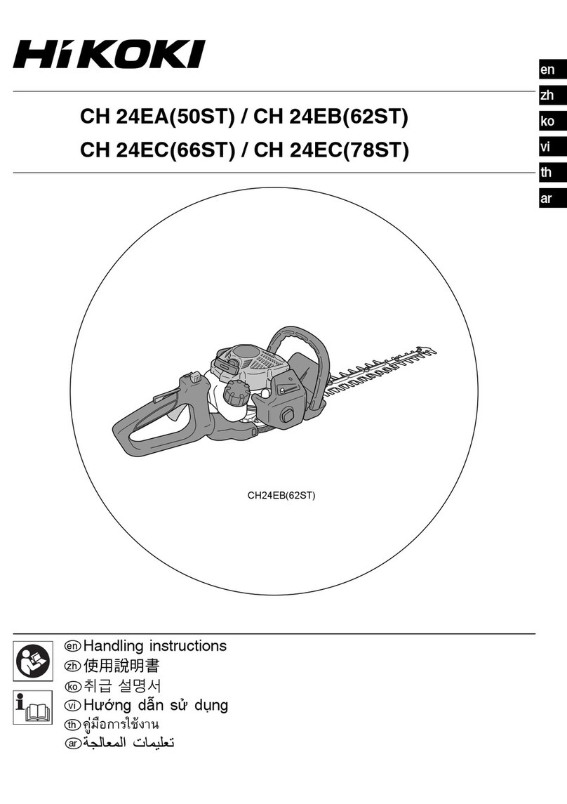
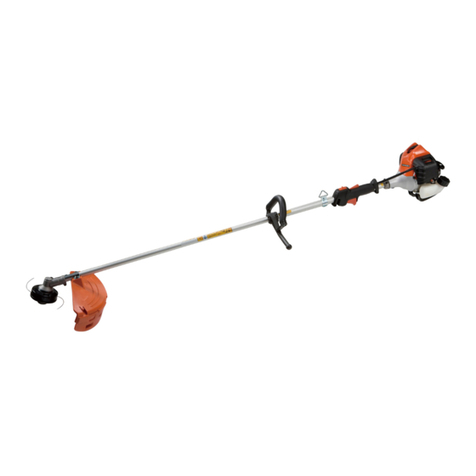
HIKOKI CG 23EC User manual

en
uk
ru
Handling instructions
Iнструкції щодо поводження зпристроєм
Инструкция по эксплуатации
en
uk
ru
CG 23EC (S)
000BookCG23EC(S).indb1000BookCG23EC(S).indb1 2018/02/279:20:492018/02/279:20:49

2
1
23
456
1/3
2/3
STX
V
U
MR
1
2
3
4
5
6
7
L
O
89
10
11
12
A
C
P
K
W
F
Q
D
E
FQ G
DCG23EC(S)
H
B
J
N
I
P
000BookCG23EC(S).indb2000BookCG23EC(S).indb2 2018/02/279:20:492018/02/279:20:49

3
789
10 11
12 13 14
15 16 17
23
18
19
20
21
22
13
13
14
16
15
17
18
19
24
000BookCG23EC(S).indb3000BookCG23EC(S).indb3 2018/02/279:20:512018/02/279:20:51

4
18 19 20
21 22 23
24 25 26
27 28 29
1/3
2/3
25
26 AA
B
B
27
28
29
24
000BookCG23EC(S).indb4000BookCG23EC(S).indb4 2018/02/279:20:532018/02/279:20:53

5
30 31 32
33 34 35
36 37
38
0.6 mm 16
30
10 cm
11-14 cm 11-14 cm
10 cm
10 cm
31
31
32
1.9-2.2 cm
35
34
33
000BookCG23EC(S).indb5000BookCG23EC(S).indb5 2018/02/279:20:542018/02/279:20:54

English
6
(Original instructions)
MEANINGS OF SYMBOLS
NOTE: Some units do not carry them.
Symbols
WARNING
The following show symbols used for the machine. Be sure that you understand their meaning before use.
Brush Cutter Blade thrust may occur when the spinning
blade contacts a solid object in the critical area.
A dangerous reaction may occur causing the
entire unit and operator to be thrust violently.
This reaction is called blade thrust. As a result,
the operator may lose control of the unit which
may cause serious or fatal injury. Blade thrust is
more likely to occur in areas where it is difficult
to see the material to be cut.
It is important that you read, fully understand
before use, and observe the following safety
precautions and warnings. Careless or improper
use of the unit may cause serious or fatal injury.
Read, understand and follow all warnings and
instructions in this manual and on the unit.
Always wear eye, head and ear protectors when
using this unit.
Hot Surface – Contact with hot surface can
cause serious burns.
Keep all children, bystandards and helpers
15 m away from the unit. If anyone approaches
you, stop the engine and cutting attachment
immediately.
Displacement
Be careful of thrown objects. Spark plug
min-1
Shows maximum shaft speed. Do not use the
cutting attachment whose max rpm is below the
shaft rpm.
Idle Idling speed
Gloves should be worn when necessary, e.g.,
when assembling cutting equipment. Speed of output shaft
Use anti-slip and sturdy footwear. PMax. engine output
Choke – Run position (Open) Fuel tank capacity
Choke – Start position (Closed) Dry weight
START
On/Start Cutting attachment
STOP
Off/Stop
LpA, eq
ISO22868
Sound pressure level LpA by ISO 22868
Equivalent*
Fuel and oil mixture
LWA, Ra(M)
2000/14/EC
Measured sound power level LwA by 2000/14/
EC
Racing
Idle speed adjustment
LWA, Ra(G)
2000/14/EC
Guaranteed sound power level LwA by
2000/14/EC
Racing
Priming pump
ahv, eq(F)
Vibration level by ISO 22867
Front or Left handle / Equivalent*
Guaranteed sound power level
ahv, eq(R)
Vibration level by ISO 22867
Rear or Right handle / Equivalent*
000BookCG23EC(S).indb6000BookCG23EC(S).indb6 2018/02/279:20:552018/02/279:20:55

English
7
KUncertainty
Before using your machine
• Read the manual carefully.
• Check that the cutting equipment is correctly assembled and adjusted.
• Start the unit and check the carburetor adjustment. See “MAINTENANCE”.
NOTE: Equivalent noise level / vibration level are calculated as the time-weighted energy total for noise / vibration levels
under various working conditions with the following time distribution:
* 1/2 Idle, 1/2 racing.
WHAT IS WHAT? (Fig. 1)
Since this manual covers several models, there may be
some difference between pictures and your unit. Use the
instructions that apply to your unit.
A: Fuel cap
B: Throttle trigger
C: Starter handle
D: Cutting attachment guard
E: Guard extension
F: Cutting attachment
G: Drive shaft tube
H: Handle
I: Hanger
J: Ignition switch
K: Spark plug
L: Priming pump
M: Harness
N: Throttle trigger lockout
O: Choke lever
P: Engine
Q: Gear case
R: Combi box spanner
S: Handling instructions
T: Goggles
U: Hex bar wrench
V: Blade cover
W: Top cover
X: Cord clump
WARNINGS AND SAFETY
INSTRUCTIONS
Pay special attention to statements preceded by the
following words:
WARNING
Indicates a strong possibility of severe personal injury or
loss of life, if instructions are not followed.
CAUTION
Indicates a possibility of personal injury or equipment
damage, if instructions are not followed.
NOTE
Helpful information for correct function and use.
Operator safety
○Wear head protection (1). (Fig. 2)
○Always wear a safety face shield or goggles (2). (Fig. 2)
○Wear approved hearing protection (3). (Fig. 2)
Long-term exposure to noise can result in permanent
hearing impairment.
Pay attention to your surroundings. Be aware of any
bystanders who may be signaling a problem.
Remove safety equipment immediately upon shutting off
engine.
○Always wear heavy, long-sleeved shirts (4) and long
pants (5) and non-slip boots (6) and gloves (7). (Fig. 2)
Do not wear loose clothing, jewelry, short pants, sandals
or go barefoot.
Secure hair so it is above shoulder length.
○Do not operate this tool when you are tired, ill or under
the influence of alcohol, drugs or medication.
○Do not operate the tool at night or under bad weather
conditions when visibility is poor. And do not operate the
tool when it is raining or right after it has been raining.
Working on slippery ground could lead to an accident if
you lose your balance.
○Never let a child or inexperienced person operate the
machine.
○Do not start the engine if there are any flammables such
as dry leaves, waste paper or fuel in the vicinity.
○Never start or run the engine inside a closed room or
building. Breathing exhaust fumes can kill.
○Keep handles free of oil and fuel.
○Keep hands away from cutting equipment.
○Do not grab or hold the unit by the cutting equipment.
○Gloves should be worn when installing or removing the
cutting attachment. Failure to do so may result in injury.
○When the unit is shut off, make sure the cutting
attachment has stopped before the unit is set down.
○When operation is prolonged, take a break periodically
so that you may avoid possible Hand-Arm Vibration
Syndrome (HAVS) which is caused by vibration.
WARNING
○Always operate the tool with proper protective equipment
and clothing. Failure to do so may result in accidents
such as burns or injuries. (Fig. 2)
○Do not touch the spark plug area or high voltage during
operation. Doing so may result in electric shock.
○Do not allow children near the tool during operation.
○Do not touch the engine, top cover or exhaust vent
during or shortly after operation. Doing so may result in
burn or injury.
○Antivibration systems do not guarantee that you will
not sustain Hand-Arm Vibration Syndrome or carpal
tunnel syndrome. Therefore, continual and regular users
should monitor closely the condition of their hands and
fingers. If any of the above symptoms appear, seek
medical advice immediately.
○If you are using any medical electric/electronic devices
such as a pacemaker, consult your physician as well as
the device manufacturer prior to operating any power
equipment.
Unit/machine safety
○Inspect the entire unit/machine before each use.
Replace damaged parts. Check for fuel leaks and make
sure all fasteners are in place and securely tightened.
○Replace parts that are cracked, chipped or damaged in
any way before using the unit/machine. Faulty parts may
increase the risk of accidents and may lead to an injury.
○Make sure the cutting attachment guard and harness are
properly attached. Do not operate if cutting attachment
guard and harness is not properly attached.
○Keep others away when making carburetor adjustments.
○Use only accessories as recommended for this unit/
machine by the manufacturer.
○Before operation, make sure that there are no tools such
as the adjustment key or spanner still attached to the
unit.
000BookCG23EC(S).indb7000BookCG23EC(S).indb7 2018/02/279:20:562018/02/279:20:56

English
8
WARNING
○Never modify the unit/machine in any way. Do not use
your unit/machine for any job except that for which it is
intended.
○Non-authorized modifications and/or accessories may
result in serious personal injury or the death of the
operator or others.
Fuel safety
○Mix and pour fuel outdoors and where there are no
sparks or flames.
○Use a container approved for fuel.
○Move at least 3 m away from fueling site before starting
engine.
○Stop engine before removing fuel cap. Do not remove
the fuel cap during operation.
○Empty the fuel tank before storing the unit/machine. It is
recommended that the fuel be emptied after each use. If
fuel is left in the tank, store so fuel will not leak.
WARNING
○Fuel is easy to ignite or get explosion or inhale fumes, so
that pay special attention when handling or filling fuel.
○Do not smoke or allow smoking near fuel or the unit/
machine or while using the unit/machine.
○Wipe up all fuel spills before starting engine.
○Store unit/machine and fuel in area where fuel vapors
cannot reach sparks or open flames from water heaters,
electric motors or switches, furnaces. etc.
○When using the unit in dry areas, make sure that fire
extinguishing equipment is readily available.
○If you shut offthe engine for refueling, make sure the unit
has cooled down before adding fuel.
Cutting safety
○Do not cut any material other than grass and brush.
○Inspect the area to be cut before each use.
Remove objects which can be thrown or become
entangled.
Do not operate in areas where there are tree roots or
rocks.
○For respiratory protection, wear an aerosol protection
mask when cutting the grass after insecticide is
scattered.
○Keep others including children, animals, bystanders and
helpers outside the 15 m hazard zone. Stop the engine
immediately if you are approached.
○Please exercise caution as engine startup may be
delayed after pulling the starter handle.
○Always keep the engine on the right side of your body.
○Hold the unit/machine firmly with both hands.
○Keep firm footing and balance. Do not over-reach.
Losing your balance during work may lead to an injury.
○Keep all parts of your body away from the muffler and
cutting attachment when the engine is running.
○Keep cutting attachment below knee level.
○Please exercise caution when operating in areas where
electrical cables or gas pipes are present.
○Do not operate the cutting attachment for anything but
clearing grass or bushes. Avoid operations where the
cutting attachment may touch water such as puddles
or dig into dirt. Failure to do so may result in injury or
damage to the unit.
○Avoid prolonged use at low speed range in which
vibration is high. Doing so may result in engine damage.
○When relocating to a new work area, or inspecting,
adjusting or exchanging the unit’s cutting attachments,
accessories, etc., be sure to shut offthe machine and
ensure that all cutting attachments are stopped.
○Never place the machine on the ground when running.
○Never touch the cutting attachment when it is rotating.
○Always ensure that the engine is shut offand any cutting
attachments have completely stopped before clearing
debris or removing grass from the cutting attachment.
○Always carry a first-aid kit when operating any power
equipment.
○Turn offthe engine and make sure the cutting attachment
has come to a full stop before removing the unit from
your body or before leaving the unit unattended.
○If you accidentally bump or drop the unit, inspect it
immediately to make sure there are no damage, cracks
or deformations.
○If the tool is operating poorly and produces strange noise
or vibrations, turn offthe engine immediately and ask
your dealer to have it inspected and repaired.
Continued use under these conditions could lead to
injury or tool damage.
○Use in accordance with local laws and regulations.
WARNING
KICKBACK DANGER (Fig. 3)
When using metal cutting attachments such as blades,
contact with obstacles such as trees or other hard
surfaces with the front or right portion of the spinning
attachment may force the unit to catch on an obstacle,
resulting in a kickback reaction towards the right side of
the operator.
Kickback may occur when the cutting attachment comes
into contact with tree stumps or rocks hidden behind
weeds. Always make sure there are no obstacles hidden
by weeds before starting work.
To minimize the danger of kickbacks when they do occur,
always position the unit to the right side of the body
during operation. With the operator properly positioned
as the cutting attachment rotates, this will reduce the
danger of the unit’s direct contact with the body.
Maintenance safety
○Maintain the unit/machine according to recommended
procedures.
○Disconnect the spark plug before performing
maintenance except for carburetor adjustments.
○Keep others away when making carburetor adjustments.
○Use only genuine HiKOKI replacement parts as
recommended by the manufacturer.
CAUTION
Do not disassemble the recoil starter. There is a
possibility of personal injury with recoil spring.
WARNING
Improper maintenance could result in serious engine
damage or in serious personal injury.
Transport and storage
○Carry the unit/machine by hand with the engine stopped
and the muffler away from your body.
○Allow the engine to cool, empty the fuel tank, and secure
the unit/machine before storing or transporting. Failure to
do so may result in fire or accidents.
○Empty the fuel tank before storing the unit/machine. It is
recommended that the fuel be emptied after each use. If
fuel is left in the tank, store so fuel will not leak.
○Store unit/machine out of the reach of children.
○Clean and maintain the unit carefully and store it in a dry
place.
○Make sure engine switch is offwhen transporting or
storing.
○When transporting and storing, either remove the cutting
attachment or place the blade cover over the blade.
○You have to secure the machine during transport to
prevent loss of fuel, damage or injury.
○If a warning label cannot be read, peels offor becomes
indistinct, replace it with a new one. To purchase new
labels, contact HiKOKI Authorized Service Centers.
If situations occur which are not covered in this manual, take
care and use common sense. Contact HiKOKI Authorized
Service Centers if you need assistance.
000BookCG23EC(S).indb8000BookCG23EC(S).indb8 2018/02/279:20:572018/02/279:20:57


English
9
SPECIFICATIONS
The SPECIFICATIONS of this machine are listed in the table
on page 40.
NOTE
All data subject to change without notice.
ASSEMBLY PROCEDURES
Installation of handle
Bike handle type (Fig. 4)
Remove the handle bracket (8) from the assembly.
Place the handles and attach the handle bracket with four
bolts lightly. Adjust to appropriate position. Then attach it
firmly with the bolts.
Attach the protection tube to the drive shaft tube or handle
using cord clamps (9) to make sure there is no slack. (Fig. 5)
Installation of harness
WARNING
If the product includes a harness, always make sure to
use it.
Attach the harness hook (10) to the hanger (11) on the drive
shaft tube. (Fig. 6)
Adjust the length of the harness for easy operation of the
tool.
NOTE
You may need to adjust the position of the hangar (11)
to balance the unit. To do so, loosen bolt (12) and adjust
the position of hangar (11). After adjusting as necessary,
make sure to securely tighten the bolt (12). (Fig. 6)
Installation of cutting attachment guard
WARNING
If an incorrect or faulty guard is fitted, this may cause
serious personal injury.
CAUTION
Some cutting attachment guards are equipped with
sharp line limiters. Be careful with handling it.
NOTE
○When using a trimmer head with two piece type cutting
attachment guard, attach the guard extension to the
cutting attachment guard, then tighten the bolt (13).
(Fig. 7)
○The guard bracket may come already mounted to the
gear case on some models.
Align the cutting attachment guard with the guard bracket (14)
and secure it to the drive shaft tube, using the bolt. (Fig. 8)
WARNING
Remove the guard extension when using metal or plastic
blades. Failure to do so may result in injury or damage to
the cutting attachment guard.
NOTE
To remove the guard extension, refer to the drawings.
Wear gloves as the extension has a sharp line limiter.
Loosen the bolt (13). Then push the three square tabs on
the guard one by one in order. (Fig. 9)
Installation of cutting attachment
WARNING
○Install the cutting attachment properly and securely as
instructed in the handling instructions.
If not attached properly or securely, it may come offand
cause serious and/or fatal injury.
○Do not install or remove cutting attachments while the
engine is running.
○Always use genuine HiKOKI cutting attachments and
metal fittings.
Installation of semi-auto cutting head
(if so equipped)
1. Function
Automatically feeds more nylon cutting line when it is
tapped at low rpm (not greater than 6000 min-1).
Specifications
Code
No.
Type of
attaching
screw
Direction of
rotation
Size of
attaching
screw
6600570 Female screw Counter-
clockwise
M10xP1.25-
LH
Applicable nylon cord
Cord diameter: Φ2.4 mm Length: 5 m
2. Precautions
○The case must be securely attached to the cover.
○Check the cover (15), case (16) and other components
for cracks or other damage. (Fig. 10)
○Check the case and button for wear.
If there is a hole in the bottom (17) of the button, change
the new parts immediately. (Fig. 10)
○The cutting head must be securely mounted to the unit’s
gear case/cutter case.
○If the cutting head does not feed cutting line properly,
check that the nylon line and all components are properly
installed. Contact HiKOKI Authorized Service Centers if
you need assistance.
WARNING
For HiKOKI heads, use only flexible, non-metallic line
recommended by the manufacturer. Never use wire or
wire ropes. They can break offand become a dangerous
projectile.
3. Installation (Fig. 11)
Insert the Hex bar wrench (18) into the hole of the gear
case and groove of the Cutter holder (A) (19) in order to
lock the shaft.
Install cutting head on gear case/cutter case of grass
trimmers/brush cutters. The mounting nut is left-hand-
threaded. Turn clockwise to loosen/counter-clockwise to
tighten.
NOTE
Since the cutter holder cap is not used here, keep it for
when a metal blade is used, if so equipped.
4. Adjusting line length
Set the engine speed as low as possible and tap the
head on the ground. The nylon line will be drawn out
about 3 cm with each tap. (Fig. 12)
Also, you can extend the nylon line by hand but the
engine must be completely stopped. (Fig. 13)
Adjust the nylon line to the proper length of 11–14 cm
before each operation.
Installation of cutting blade (Fig. 14)
(If so equipped)
Insert the Hex bar wrench (18) into the hole of the gear case
and groove of the Cutter holder (A) (19) in order to lock the
shaft.
Assemble in the following order: Cutter holder (A) (19),
blade (20), cutter holder (B) (21), nut cover (22).
Tighten the fixing nut with the combi box spanner with a
tightening torque of 14
±
2 N.m. Please note that the cutter
fixing nut (23) has left-handed threads (clockwise to loosen/
counter-clockwise to tighten).
NOTE
○When installing cutter holder (B) (21), be sure to set
concave side upward.
000BookCG23EC(S).indb9000BookCG23EC(S).indb9 2018/02/279:20:572018/02/279:20:57
English
10
○When installing or removing a blade, make sure to wear
gloves and place the blade cover over the blade.
CAUTION
Check a nut cover (22) for wear or cracks before
operation. If any damage or wear is found, replace it, as
it is an article of consumption.
WARNING
○When installing a cutting blade, make sure that there are
no cracks or any damage in it and that the cutting edges
are facing the correct direction.
○Remove any surface grit from blade installation fittings
(cutter holder (A) (19), cutter holder (B) (21), nut
cover (22), nut (23)). Failure to do so may result in the
loosening of nuts.
○The protrusion of the cutter holder (A) (19) may become
misaligned with the blade (20) while tightening nut
(23). Before operation, make sure the blade has been
properly installed. (Fig. 15)
○Rotate the blade by hand and make sure there is no
rocking or abnormal noise. Rocking may cause abnormal
vibrations or result in the loosening of nuts.
OPERATING PROCEDURES
Fuel (Fig. 16)
WARNING
○The trimmer is equipped with a two-stroke engine.
Always run the engine on fuel, which is mixed with oil.
Provide good ventilation, when fueling or handling fuel.
○Fuel is highly flammable and it is possible to get seriously
injured when inhaling or spilling on your body.
Always pay attention when handling fuel. Always have
good ventilation when handling fuel inside building.
Fuel
○Always use branded 89 octane unleaded gasoline.
○Use genuine two-cycle oil or use a mix between 25:1 to
50:1, please consult about the mixture ratio to HiKOKI
Authorized Service Centers.
○If genuine oil is not available, use an anti-oxidant added
quality oil expressly labeled for air-cooled 2-cycle engine
use (JASO FC GRADE OIL or ISO EGC GRADE). Do not
use BIA or TCW (2-stroke water-cooling type) mixed oil.
○Never use multi-grade oil (10 W/30) or waste oil.
○Never mix fuel and oil in machine’s fuel tank. Always mix
fuel and oil in a separate clean container.
Always start by filling half the amount of gasoline, which is
to be used.
Then add the whole amount of oil. Mix (shake) the fuel
mixture. Add the remaining amount of gasoline.
Mix (shake) the fuel-mix thoroughly before filling the fuel
tank.
Mixing amount of two-cycle oil and gasoline
Gasoline (Liter) Two-cycle oil (ml)
Ratio 50:1 Ratio 25:1
0.5 10 ——— 20
1 20 ——— 40
2 40 ——— 80
4 80 ——— 160
Fueling
WARNING
○Always shut offthe engine and let it cool for a few
minutes before refueling.
Do not smoke or bring flames or sparks near the fueling
site.
○Slowly open the fuel tank, when filling up with fuel, so
that possible over-pressure disappears.
○Tighten the fuel tank cap carefully, after fueling.
○Always move the unit at least 3 m from the fueling area
before starting.
○Always wash any spilled fuel from clothing immediately
with soap.
○Be sure to check any fuel leakage after refueling.
○Before fueling, in order to remove static electricity from
the main body, the fuel container and the operator,
please touch the ground that is slightly damp.
Before fueling, clean the tank cap area carefully, to ensure
that no dirt falls into the tank. Make sure that the fuel is well
mixed by shaking the container, before fueling.
Starting
CAUTION
Before starting, make sure the cutting attachment does
not touch anything.
(1) Starting the cold engine
1. Set ignition switch (24) to ON position. (Fig. 17)
2. Push priming pump (25) several times so that fuel flows
through return pipe (26). (Fig. 18)
3. Set choke lever (27) to START position (closed) (A).
(Fig. 19)
4. Pull recoil starter briskly, taking care to keep the handle
in your grasp and not allowing it to snap back. (Fig. 20)
5. When you hear the engine want to start, return choke
lever to RUN position (open) (B). (Fig. 19)
6. Pull recoil starter briskly again. (Fig. 20)
NOTE
If engine does not start, repeat procedures from 2 to 5.
7. Then allow the engine about 2–3 minutes to warm up
before subjecting it to any load.
8. Check that the cutting attachment does not rotate when
the engine is idling.
(2) Starting the warm engine
Use only 1, 6 and 8 of the starting procedure for a cold
engine.
If the engine does not start, use the same starting
procedure as for a cold engine.
Cutting
WARNING
○Always use the harness and wear the proper attire and
protective equipment when operating the unit. (Fig. 21)
○Keep others including children, animals, bystanders and
helpers outside the 15 m hazard zone. Stop the engine
immediately if you are approached. (Fig. 22)
○When grass or vines wrap around attachment, stop engine
and attachment and remove them. Continuing operation
with grass or vines wrapped around the attachment may
result in damages such as early abrasion of the clutch.
CAUTION
Use and points of caution will vary depending on the type
of cutting attachment. For safe use, make sure to follow
the instructions and guidelines provided with each type.
NOTE
○Press the quick release button or pull emergency release
flap (If so equipped) in the event of emergency. (Fig. 23)
○Use in accordance with local laws and regulations.
(1) Using a semi-auto cutting head
○Set the engine at high speed when using this attachment.
○Cut grass from left to right. The cut grass will be
discharged away from the body, minimizing transfer to
your clothes. (Fig. 24)
○Cut grass from right to left as the cutting attachment of
the curved drive shaft tube model rotates clockwise.
000BookCG23EC(S).indb10000BookCG23EC(S).indb10 2018/02/279:20:572018/02/279:20:57

English
11
○With nylon cord, use about 2 cm of the end of the cord
to cut grass. Using the full length of the cord will reduce
rotation speed and make cutting difficult.
NOTE
Automatically feeds more nylon cutting line when it is
tapped at low rpm (not greater than 6000 min-1).
WARNING
○This product is equipped with a line limiter that will
automatically cut any excess cord. When operating the
unit, do not remove the guard or line limiter.
As the resistance is greater for nylon cords as opposed
to blades, mishandling could increase engine load and
result in damage.
○Do not use with the engine set at low speeds. If the
engine speed is low, grass may wrap around the
attachment, causing the clutch to slip which could result
in clutch abrasion.
○With nylon cord cutters, always use over 15 cm of cord.
If the length of the cord is too short, rotation speed will
increase and may cause damage to the nylon cord
cutter. As the curved drive shaft tube model in particular
is not equipped with a deceleration mechanism, the
possibility of increased rotation speed for the cutting
attachment is high.
(2) Using a blade
○Adjust engine speed according to the resistance of the
grass. For soft grass, use low speeds, For tough clumps
of grass, use high speeds.
○Cut grass from right to left, using the left side of the blade
to cut. (Fig. 25)
○Slightly tilting the blade to the left while cutting will pile
the cut grass to the left, making collection easy.
NOTE
Excessively increasing rotation speed may cause
increased blade wear, vibration and noise. It will also
result in increased fuel consumption.
WARNING
○Blade thrust may occur when the spinning blade contacts
a solid object in the critical area.
A dangerous reaction may occur causing the entire unit
and operator to be thrust violently. This reaction is called
blade thrust. As a result, the operator may lose control
of the unit which may cause serious or fatal injury. Blade
thrust is more likely to occur in areas where it is difficult
to see the material to be cut.
○If cutting attachment should strike against stones or
other debris, stop the engine and make sure that the
attachment and related parts are undamaged.
Stopping (Fig. 26)
Decrease engine speed and run at an idle for a few minutes,
then turn offignition switch (24).
WARNING
A cutting attachment can injure while it continues to spin
after the engine is stopped or Throttle trigger is released.
When the unit is turned off, make sure the cutting
attachment has stopped before the unit is set down.
MAINTENANCE
MAINTENANCE, REPLACEMENT OR REPAIR OF THE
EMISSION CONTROL DEVICES AND SYSTEMS MAY
BE PERFORMED BY ANY NON-ROAD ENGINE REPAIR
ESTABLISHMENT OR INDIVIDUAL.
Carburetor adjustment (Fig. 27)
WARNING
○The cutting attachment may be spinning during
carburetor adjustments.
○Never start the engine without the complete clutch cover
and tube assembled! Otherwise the clutch can come
loose and cause personal injuries.
In the carburetor, fuel is mixed with air. When the engine is
test run at the factory, the carburetor is adjusted. A further
adjustment may be required, according to climate and
altitude. The carburetor has one adjustment possibility:
T = Idle speed adjustment screw.
Idle speed adjustment (T)
Check that the air filter is clean. When the idle speed is
correct, the cutting attachment will not rotate. If adjustment
is required, close (clockwise) the T-screw, with the engine
running, until the cutting attachment starts to rotate. Open
(counter-clockwise) the screw until the cutting attachment
stops. You have reached the correct idle speed when the
engine runs smoothly in all positions well below the rpm
when the cutting attachment starts to rotate.
If the cutting attachment still rotates after idle speed
adjustment, contact HiKOKI Authorized Service Centers.
NOTE
Standard Idle rpm is 3000 – 3400 min-1.
WARNING
When the engine is idling the cutting attachment must
under no circumstances rotate.
Air filter (Fig. 28)
The air filter (28) must be cleaned from dust and dirt in order
to avoid:
○Carburetor malfunctions.
○Starting problems.
○Engine power reduction.
○Unnecessary wear on the engine parts.
○Abnormal fuel consumption.
Clean the air filter daily or more often if working in
exceptionally dusty areas.
Open the air filter cover and remove the air filter (28). Clean it.
Check that the filter is dry before reassembly.
An air filter that has been used for some time cannot be
cleaned completely. Therefore, it must regularly be replaced
with a new one. A damaged filter must always be replaced.
NOTE
To put the air filter cover back into place, hook it on the
upper tabs and then attach it.
Fuel filter (Fig. 29)
Remove the fuel filter (29) from the fuel tank, and replace it if
it is dirty.
NOTE
A blocked fuel filter (29) can prevent the supply of fuel and
cause a rotation malfunction of the engine.
Spark plug (Fig. 30)
The spark plug condition is influenced by:
○An incorrect carburetor setting.
○Wrong fuel mixture (too much oil in the gasoline)
○A dirty air filter.
○Hard running conditions (such as cold weather).
These factors cause deposits on the spark plug electrodes,
which may result in malfunction and starting difficulties. If
the engine is low on power, difficult to start or runs poorly at
idling speed, always check the spark plug first.
If the spark plug is dirty, clean it and check the electrode
gap. Re-adjust if necessary. The correct gap is 0.6 mm. The
spark plug should be replaced after about 100 operation
hours or earlier if the electrodes are badly eroded.
000BookCG23EC(S).indb11000BookCG23EC(S).indb11 2018/02/279:20:572018/02/279:20:57
English
12
NOTE
In some areas, local law requires using a resistor spark
plug to suppress ignition signals. If this machine was
originally equipped with resistor spark plug, use same
type of spark plug for replacement.
Gear case (Fig. 31)
Check gear case or angle gear for grease level about every
50 hours of operation by removing the grease filler plug on
the side of gear case.
If no grease can be seen on the flanks of the gears, fill the
gear case with quality lithium based multipurpose grease up
to 3/4. Do not completely fill the gear case.
CAUTION
○Make sure to remove any dirt or grit when attaching the
plug to its original position.
○Before attempting inspection or maintenance of the gear
case, make sure the case has cooled.
Semi-auto cutting head
Nylon line replacement
1. Remove the case (16) by firmly pushing inward the
locking tabs with your thumbs as shown in Fig. 32.
2. After removing the case, take out the reel and discard
the remaining line.
3. Fold the new nylon line unevenly (approx. 10 cm) in half
as shown in picture.
Hook the U-shaped end of the nylon line into the groove
(30) on the center partition of the reel.
Wind both halves of the line on the reel in the same
direction, keeping each half of the line on its own side of
the partition. (Fig. 33)
4. Push each line into the stopper holes (31), leaving the
loose ends approx. 10 cm in length. (Fig. 34)
5. Insert both loose ends of the line through the cord guide
(32) when placing the reel in the case. (Fig. 35)
NOTE
When placing a reel in the case, try to line up the stopper
holes (31) with the cord guide (32) for easier line release
later.
6. Place the cover over the case so that the cap locking
tabs (34) on the cover meet the long holes (33) on the
case. Then push the case securely until it clicks into
place. (Fig. 36)
7. The initial cutting line length should be approx. 11–14 cm
and should be equal on both sides. (Fig. 37)
Blade (Fig. 38)
WARNING
Wear protective gloves when handling or performing
maintenance on the blade.
○Use a sharp blade. A dull blade is more likely to snag and
thrust.
Replace the fastening nut if it is damaged and hard to
tighten.
○When replacing blade, purchase one recommended by
HiKOKI, with a 25.4 mm (one inch) fitting hole.
○In the case of a 3 tooth blade (35), it can be used on
either side.
○Use the correct blade for the type of work.
○When replacing blades, use appropriate tools.
○When cutting edges become dull, re-sharpen or file
as shown in the illustration. Incorrect sharpening may
cause excessive vibration.
○Discard blades that are bent, warped, cracked, broken
or damaged in any way.
NOTE
When sharpening blade it is important to maintain an
original shape of radius at the base of the tooth to avoid
cracking.
For long-term storage
Drain all fuel from the fuel tank. Start and let engine run until
it stops. Repair any damage which has resulted from use.
Clean the unit with a clean rag, or the use of high pressure
air hose. Put a few drops of two-cycle engine oil into the
cylinder through the spark plug hole, and spin the engine
over several times to distribute oil.
Cover the unit and store it in a dry area.
Maintenance schedule
Below you will find some general maintenance instructions.
For further information please contact HiKOKI Authorized
Service Centers.
Daily maintenance
○Clean the exterior of the unit.
○Check that the harness is undamaged.
○Check the cutting attachment guard for damage or
cracks. Change the guard in case of impacts or cracks.
○Check that the cutting attachment is properly centered,
sharp, and without cracks. An off-center cutting
attachment induces heavy vibrations that may damage
the unit.
○Check that the cutting attachment nut is sufficiently
tightened.
○Make sure that the blade cover is undamaged and that it
can be securely fitted.
○Check that nuts and screws are sufficiently tightened.
○Check that the unit is undamaged and free of defects.
Weekly maintenance
○Check the starter, especially the cord.
○Clean the exterior of the spark plug.
○Remove the spark plug and check the electrode gap.
Adjust it to 0.6 mm, or change the spark plug.
○Check that the angle gear is filled with grease up to 3/4.
○Clean the air filter.
Monthly maintenance
○Rinse the fuel tank with gasoline.
○Clean the exterior of the carburetor and the space
around it.
○Clean the fan and the space around it.
SELECTING ACCESSORIES
The accessories of this machine are listed on page 41.
000BookCG23EC(S).indb12000BookCG23EC(S).indb12 2018/02/279:20:572018/02/279:20:57
English
13
SELECTING CUTTING ATTACHMENTS
Recommended accessories for each model are presented in the table below.
For purchases, contact HiKOKI Authorized Service Centers.
Please check carefully as those accessories not marked with “●” cannot be attached.
List of recommended accessories
Type Name
Specification
BIKE
HANDLE
Diameter
Feed System Adapter
or
No. of Teeth (Blade)
Blade Thickness (mm)
or
Trimmer line Diameter
(mm)
CG23EC (S)
ALUMINUM HEADS
NYLON HEAD
CH-100
(W/NYLON LINE) 4” Pre-Cut Line 2.2 – 3.0
●
NYLON HEAD
CH-100 ●
NYLON HEAD
CH-300
(W/CUTTER HOLDER CAP) 5” Manual line feed 2.2 – 2.7
NYLON HEAD
CH-300
AUTO NYLON
HEADS
NYLON HEAD
TH-97M 5” L M10 x 1.25 Nut 2.4 – 2.7
NYLON HEAD
TH-97U2 5” L M10 x 1.25 Nut
L M8 x 1.25 Nut 2.4 – 2.7
TAP & GO NYLON HEADS
NYLON HEAD
BF-4 4” R M8 x 1.25 Nut 2.2 – 3.0
NYLON HEAD (R)
(G137-301) 4” R M8 x 1.25 Nut 2.0 – 2.8
NYLON HEAD 4” L M10 x 1.25 Nut 2.4 ●
NYLON HEAD 4” R M8 x 1.25 Nut 2.4
NYLON HEAD
BF-5 5” L M10 x 1.25 Nut
L M8 x 1.25 Nut 2.2 – 3.0 ●
NYLON HEAD ASS’Y
(G138-501) 4” L M10 x 1.25 Nut 2.0 – 2.8 ●
NYLON HEAD ASS’Y
(S128-500) 5” L M10 x 1.25 Nut 2.0 – 3.0
BLADES
BLADE
B3/10/1.8 10” 3 1.8 ●
BLADE
B3/10/2.01 10” 3 2.0
BLADE
B3/12/3.0 12” 3 3.0
BLADE
B4/9/1.6 9” 4 1.6 ●
BLADE
B4/10/1.6 10” 4 1.6 ●
000BookCG23EC(S).indb13000BookCG23EC(S).indb13 2018/02/279:20:572018/02/279:20:57
English
14
TROUBLESHOOTING
Use the inspections in the table below if the tool does not operate normally. If this does not remedy the problem, consult your
dealer or the HiKOKI Authorized Service Center.
Condition Cause Remedy
Engine does not
start
Fuel
system
Fuel tank is empty or fuel level is low Fill the fuel tank with the correct fuel mix
(25:1-50:1)
Fuel tank contains old fuel (offensive odor)
Replace with new fuel
Too much fuel is absorbed and spark
plug is wet
1.
Disconnect the spark plug and allow to dry
2.Pull the starter handle 5 or 6 times to
remove the surplus fuel
3.Attach the spark plug
4.Set the choke lever to RUN position and
pull the starter handle
Fuel filter is clogged with dirt Clean the fuel filter
Fuel pipe is bent or disconnected Ensure that the fuel flows smoothly
Carburetor malfunction Contact HiKOKI Authorized Service Centers
Electrical
system
Stop switch lead has short-circuited Contact HiKOKI Authorized Service Centers
Spark plug is dirty Replace or clean the spark plug
Electrode gap is too big Adjust the gap to 0.6mm
Poor connection between high tension
cable and spark plug Reconnect
Electrical system malfunction Contact HiKOKI Authorized Service Centers
Other Muffler exhaust port is clogged with
carbon
Contact HiKOKI Authorized Service Centers
for repair
Engine starts
but cuts out
straightaway
Engine is apt to
cut out
Fuel
system
Fuel tank is empty or fuel level is low Fill the fuel tank with the correct fuel mix
(25:1-50:1)
Fuel tank contains old fuel (offensive odor)
Replace with new fuel
Two-cycle oil has not been added Contact HiKOKI Authorized Service Centers
Choke lever is in START position Set the choke lever to RUN position
Air has got into fuel system Reconnect the fuel pipe or joint
Carburetor malfunction Contact HiKOKI Authorized Service Centers
Electrical
system
Ignition failure
Spark plug failure Replace with new spark plug
Electrical system failure Contact HiKOKI Authorized Service Centers
Other
Engine overheating
Wrong spark plug model Replace with designated part
See “SPECIFICATIONS”
Dirty air cleaner Clean
Carbon clogging (muffler exhaust port) Clean
Insufficient compression (piston, piston
ring, cylinder) Contact HiKOKI Authorized Service Centers
Abnormal vibration
Cutting attachment is not properly
installed See “Installation of cutting attachment”
Handle, handle bracket or other
fastening part is loose Check and tighten
Blade is bent or damaged Replace with new blade
Grass is wrapped round gear case Remove grass
Engine is running but blade
does not move
Movement is poor
Grass is wrapped round gear case Remove grass and dirt
000BookCG23EC(S).indb14000BookCG23EC(S).indb14 2018/02/279:20:582018/02/279:20:58

English
15
Condition Cause Remedy
Engine does not stop Stop switch failure
Set the choke lever to START position to
stop the engine
Cease use immediately and contact HiKOKI
Authorized Service Centers
Engine stops when throttle is
closed
Idle speed is too low
Contact HiKOKI Authorized Service Centers
Blade continues rotating when
throttle is closed
Idle speed is too high
Throttle wire is too taut Contact HiKOKI Authorized Service Centers
000BookCG23EC(S).indb15000BookCG23EC(S).indb15 2018/02/279:20:582018/02/279:20:58

Українська
16
(Переклад первинних інструкцій)
ЗНАЧЕННЯ СИМВОЛІВ
ПРИМІТКА:На деяких виробах вони не зазначаються.
Символи
ПОПЕРЕДЖЕННЯ
Нижче наведено символи, які зазначаються на пристрої. Перш ніж користуватися пристроєм, ви
повинні зрозуміти їх значення.
Кущів Гарантований рівень звукової потужності
Обов’язково перед використанням прочитайте
йцілком іповністю зрозумійте викладені далі
правила техніки безпеки та попередження й
завжди їх дотримуйтесь. Недбале або неналежне
користування пристроєм може призвести до
серйозного травмування або смерті.
Лезо може заклинити, коли під час
обертання контактує зтвердим об’єктом у
критичній зоні. Може трапитися небезпечна
реакція, спричинивши несамовитий
поштовх всього пристрою та користувача.
Ця реакція називається заклиненням леза.
Як наслідок, користувач може втратити
контроль над керуванням пристроєм,
що може призвести до серйозного або
смертельного травмування. Заклинення
леза найбільш ймовірно може трапитися в
місцях, де важко побачити матеріал, який
потрібно розрізати.
Необхідно прочитати, зрозуміти усі
попередження йвказівки, зазначені вцьому
посібнику та безпосередньо на пристрої, та
завжди їх дотримуватися.
На час користування пристроєм завжди
одягайте захисні окуляри, шолом та
шумопоглинальні навушники.
Забезпечте, щоб діти, сторонні особи
та помічники знаходилися на відстані
15мвід пристрою. Негайно зупиніть
двигун та різальний пристрій, якщо хтось
наближається до вас.
Гаряча поверхня – Контакт згарячою
поверхнею може призвести до серйозних
опіків.
Будьте обережні звідкинутими об’єктами.Об’єм двигуна
min-1
Показує максимальну швидкість валу.
Не використовуйте різальний пристрій,
максимальні об/хв якого менші за об/хв вала.
Свічка запалювання
Уразі необхідності слід надягати рукавички,
наприклад, при складанні різального
обладнання.
Idle Швидкість холостого ходу двигуна
Використовуйте міцне взуття зпідошвою, що
не ковзає.Швидкість вихідного валу
Повітряна заслінка – робоче положення
(Відкрито)PМакс. потужність двигуна
Повітряна заслінка – Стартова позиція
(Закрито)Ємність паливного бака
START
Увімкнути/Запуск Суха маса
STOP
Вимкнути/Стоп Різальний пристрій
Суміш пального та мастила
LpA, eq
ISO22868
Рівень звукового тиску LpАзгідно зISO
22868 еквівалент*
Регулювання швидкості холостого ходу
LWA, Ra(M)
2000/14/EC
Рівень виміряної звукової потужності LwA
згідно 2000/14/EC
Розгін (двигуна)
Пускова помпа
LWA, Ra(G)
2000/14/EC
Рівень гарантованої звукової потужності
LwA згідно 2000/14/EC
Розгін (двигуна)
000BookCG23EC(S).indb16000BookCG23EC(S).indb16 2018/02/279:20:582018/02/279:20:58

Українська
17
ahv, eq(F)
Рівень вібрації згідно зISO 22867
Передня або ліва ручка/Еквівалент*KПохибка
ahv, eq(R)
Рівень вібрації згідно зISO 22867
Задня або Права ручка/Еквівалент*
Перед використанням пристрою
• Уважно прочитайте посібник зкористування.
• Перевірте чи різальне обладнання належним чином зібрано та відрегульовано.
• Увімкніть пристрій іперевірте налаштування карбюратора. Дивіться розділ «ТЕХОБСЛУГОВУВАННЯ».
ПРИМІТКА: Еквівалентні рівні шуму / вібрації обчислюються, як зважена за часом сумарна енергія для рівнів шуму
/ вібрації за різних робочих умов та за наступного часового розподілу:
* 1/2 холостого ходу, 1/2 робочого ходу.
КОМПОНЕНТИ (Мал. 1)
Оскільки цей посібник стосується декількох моделей,
фактичний вигляд вашого пристрою може дещо
відрізнятися від наведених зображень. Користуйтеся
вказівками, які стосуються вашого пристрою.
A: Кришка паливного бака
B: Дросельний важіль
C: Ручка стартера
D: Захист різального пристрою
E: Захисна додаткова насадка
F: Різальний пристрій
G: Труба карданного валу
H: Ручка
I: Гак
J: Перемикач запалювання
K: Свічка запалювання
L: Пусковий насос
M: Ремінь безпеки
N: Блокування дросельного важеля
O: Важіль заслінки
P: Двигун
Q: Редуктор
R: Комбінований торцевий ключ
S: Інструкції зексплуатації
T: Захисні окуляри
U: Шестигранний ключ
V: Кришка леза
W: Верхня кришка
X: Набір шнурів
ПОПЕРЕДЖЕННЯ ТА ПРАВИЛА
ТЕХНІКИ БЕЗПЕКИ
Зверніть особливу увагу на вказівки, що
супроводжуються такими словами:
ПОПЕРЕДЖЕННЯ
Вказує на значну ймовірність фізичного травмування
або летальних наслідків уразі недотримання
вказівок.
ОБЕРЕЖНО
Вказує на можливість фізичного травмування або
пошкодження пристрою вразі недотримання вказівок.
ПРИМІТКА
Кориснаінформаціящодо належногофункціонування
та використання пристрою.
Безпека користувача
○Носити засоби захисту голови (1). (мал. 2)
○Завжди одягайте щиток для обличчя або захисні
окуляри (2). (мал. 2)
○Носити рекомендовані засоби захисту слуху (3).
(мал. 2)
Довготривала дія шуму може спричинити постійне
погіршення слуху.
Слідкуйте за навколишнім середовищем. Звертайте
увагу на людей, які можуть повідомляти про якісь
проблеми.
Видаляйте захисне обладнання відразу після
відключення двигуна.
○Завжди носіть важкі сорочки здовгими рукавами
(4), довгі штани (5), черевики зпідошвою, що не
ковзає (6) та рукавички (7). (мал. 2)
Не одягайте вільний одяг, прикраси, короткі штани,
сандалі та не користуйтеся пристроєм босоніж.
Підбирайте волосся, щоб воно було вище плечей.
○Не користуйтеся пристроєм, якщо ви втомлені,
погано почуваєтесь або перебуваєте під впливом
алкоголю, наркотичних засобів або медичних
препаратів.
○Не користуйтеся пристроєм вночі або за поганих
погодних умов, коли погана видимість. Також не
користуйтеся інструментом, коли дощить або
відразу після закінчення дощу.
Робота на слизькому ґрунті може призвести до
нещасного випадку, якщо ви втратите рівновагу.
○Ніколи не дозволяйте дитині чи недосвідченій особі
користуватися пристроєм.
○Не запускайте двигун, якщо поблизу знаходяться
легкозаймисті матеріали, такі як сухе листя,
макулатура чи пальне.
○Ніколи не запускайте та не використовуйте
пристрій узакритій кімнаті чи приміщенні. Вдихання
вихлопних газів може бути смертельним.
○Слідкуйте, щоб на ручках не накопичувалися
мастило та пальне.
○Не торкайтеся руками різального обладнання.
○Не беріть іне тримайте пристрій за різальне
обладнання.
○Слід одягати рукавички під час встановлення або
усунення різального пристрою. Недотримання цієї
вимоги може призвести до травм.
○Перед тим, як покласти пристрій після вимкнення,
переконайтеся, що різальний механізм зупинився.
○Уразі тривалого використання пристрою час від часу
робіть перерви, щоб уникнути вібраційної хвороби,
яка спричиняється вібрацією.
ПОПЕРЕДЖЕННЯ
○Завжди користуйтеся інструментом уналежному
захисному обладнанні та одязі. Недотримання цього
може призвести до нещасних випадків, таких як
опіки чи травми. (мал. 2)
○Не торкайтеся зони виникнення іскри чи високої
напруги під час роботи. Це може призвести до
ураження електричним струмом.
○Не дозволяйте дітям знаходитися біля пристрою під
час роботи.
○Не торкайтеся двигуна, верхньої кришки або
витяжного вентиляційного відводу під час роботи
або відразу після роботи.Це може призвести до
опіків або травм.
000BookCG23EC(S).indb17000BookCG23EC(S).indb17 2018/02/279:20:592018/02/279:20:59

Українська
18
○Противібраційні системи не гарантують захист від
вібраційної хвороби чи синдрому зап’ястного каналу.
Тому вразі тривалого або регулярного використання
пристрою слід ретельно стежити за станом рук
та пальців. Якщо з’явиться один із згаданих вище
симптомів, слід негайно звернутися до лікаря.
○Якщо ви використовуєте будь-які електричні/
електронні медичні пристрої, наприклад
кардіостимулятор, проконсультуйтеся злікарем
та виробником пристрою, перш ніж користуватися
електросиловим обладнанням.
Безпека пристрою/машини
○Оглядайте пристрій/машину щоразу перед
використанням. Замініть пошкоджені деталі.
Перевіряйте відсутність витоку пального інадійність
фіксації кріплень.
○Слід замінити деталі, що тріснули, надщербилися чи
іншим чином пошкодилися, перед використанням
пристрою/машини. Пошкоджені деталі збільшують
ризик нещасних випадків іможуть призвести до
травми.
○Переконайтеся, що захист різального механізма
та ремінь безпеки правильно під’єднані. Не
користуйтеся пристроєм, якщо захист різального
механізму та ремінь безпеки не під’єднані правильно.
○Поблизу не має бути сторонніх людей під час
регулювання карбюратора.
○Використовуйте лише те обладнання, яке схвалені
виробником пристрою/машини.
○Перед початком роботи переконайтеся, що жоден
інструмент, такий як ключ регулювання або гайковий
ключ, не під’єднаний до пристрою.
ПОПЕРЕДЖЕННЯ
○За жодних умов не виконуйте ніяких модифікацій
пристрою/машини. Використовуйте пристрій/
машину суворо за призначенням.
○Недозволені зміни та/або аксесуари можуть
призвести до серйозних травм або смерті
користувача чи інших осіб.
Безпека використання пального
○Змішуйте пальне та наповнюйте паливний бак на
відкритому повітрі та за відсутності джерел іскор або
відкритого вогню.
○Використовуйте відповідний паливний контейнер.
○Відійдіть від місця наповнення паливного бака
щонайменше на 3 мперед тим, як запустити двигун
пристрою.
○Зупиніть двигун перед тим, як зняти кришку
паливного бака. Не знімайте кришку паливного бака
під час роботи.
○Злийте паливо зпаливного бака, якщо не плануєте
використовувати пристрій/машину упродовж
певного часу. Радимо випорожнювати паливний бак
після кожного використання пристрою. Якщо пальне
таки залишилося вбаку, зберігайте пристрій так,
щоб воно не витікало.
ПОПЕРЕДЖЕННЯ
○Пальне єлегкозаймистою та вибухонебезпечною
речовиною, також воно виділяє випари, тому під час
користування ним слід бути особливо обережним.
○Не паліть іне дозволяйте іншим палити поблизу
паливного контейнера або пристрою/машини, а
також під час використання пристрою/машини.
○Повитирайте всі бризки пального, перш ніж
запустити двигун пристрою.
○Зберігайте пристрій/машину та паливо умісцях, де
випари пального не матимуть контакту зіскрами
або відкритим вогнем, джерелами яких можуть бути
нагрівачі води, електричні двигуни чи вимикачі, печі
тощо.
○Використовуючи пристрій упосушливих районах,
переконайтеся, що засоби пожежогасіння легко
доступні.
○Якщо ви вимкнете двигун для заправки,
переконайтеся, що пристрій охолонув, перш ніж
долити паливо.
Безпека під час різального процесу
○Не зрізайте нічого, крім трави та кущів.
○Оглядайте робочу ділянку щоразу перед початком
використання пристрою.
Прибирайте предмети, які пристрій може відкинути
або вяких можна заплутатися.
Не користуйтеся пристроєм умісцях, де єкоріння
дерев або каміння.
○Якщо зрізання трави здійснюється після розпилення
інсектициду, одягайте маску для захисту дихальних
шляхів від аерозольних крапель.
○Урадіусі 15 мвід небезпечної зони не повинні
перебувати діти, тварини, інші сторонні особи чи
помічники. Одразу вимикайте двигун, якщо до вас
хтось наближається.
○Будь ласка, будьте уважні, так як запуск двигуна
може бути відкладено після того, як ви потягнули за
ручку стартера.
○Завжди тримайте двигун на правій стороні вашого
тіла.
○Надійно тримайте пристрій/машину обома руками.
○Зберігайте стійке положення та рівновагу. Не
намагайтесь дотягнутися до віддалених місць.
Втрата рівноваги під час роботи може призвести до
травми.
○Під час роботи двигуна тримайте всі частини тіла
подалі від глушника та різального механізму.
○Тримайте різальний механізм нижче рівня колін.
○Будь ласка, будьте уважні під час роботи умісцях, де
єелектричні кабелі та газові труби.
○
Не використовуйте різальний пристрій ні для чого, крім
очищення трави та кущів. Уникайте дій, де різальний
пристрій може торкнутися води, такої як калюжі,
або захопити бруд. Недотримання цієї вимоги може
призвести до травми або пошкодження пристрою.
○Уникайте тривалого використання на низьких
швидкостях, під час якого вібрація євисокою. Це
може призвести до пошкодження двигуна.
○При переміщенні внову робочу зону або при огляді,
налаштуванні або заміні різальних механізмів,
обладнання іт.д. пристрою, переконайтеся, що
машина вимкнена ізабезпечте, щоб всі різальні
механізми було зупинено.
○Ніколи не кладіть увімкнений пристрій на землю.
○Ніколи не торкайтеся різального пристрою під час
його роботи.
○Необхідно відключити двигун ідочекатися повної
зупинки різального пристрою, перш ніж видаляти
обрізки або траву зрізального пристрою.
○Слід завжди мати при собі аптечку першої допомоги,
користуючись будь-яким силовим обладнанням.
○Вимкніть двигун іпереконайтеся, що різальний
механізм повністю зупинився перед від'єднанням
від вашого тіла або перед залишенням пристрою без
нагляду.
○Якщо ви випадково вдарили або випустили зрук
пристрій, негайно огляньте його, щоб переконатися,
що немає пошкоджень, тріщин або деформацій.
○Якщо інструмент працює погано івиробляє дивний
шум або вібрацію, негайно вимкніть двигун і
зверніться до свого дилера для огляду та ремонту.
Тривале використання за цих умов може призвести
до травмування або пошкодження інструмента.
○Використовуйте відповідно до місцевих законів та
інструкцій.
000BookCG23EC(S).indb18000BookCG23EC(S).indb18 2018/02/279:20:592018/02/279:20:59

Українська
19
ПОПЕРЕДЖЕННЯ
НЕБЕЗПЕКА ВІДДАЧІ (мал. 3)
При використанні металевого різального
обладнання, такого як лезо, контакт зперешкодами,
такими як дерева або інші тверді поверхні, з
передньою або правою частиною механізму
обертання може змусити пристрій зловити
перешкоду, врезультаті чого відбудеться реакція
віддачі управий бік користувача.
Віддача може виникнути, коли різальне устаткування
натрапляє на пеньки або каміння, приховані за
бур'янами. Завжди переконайтеся, що немає
перешкод, прихованих убур’янах, перед початком
роботи.
Щоб мінімізувати небезпеку віддач, якщо вони
трапляються, завжди розміщуйте пристрій зправого
боку тіла під час роботи. Якщо користувач зайняв
правильну позицію під час обертання різального
пристрою, це зменшить небезпеку прямого контакту
пристрою зтілом.
Безпека техобслуговування
○Здійснюйте техобслуговування пристрою відповідно
до рекомендованих процедур.
○Перед виконанням техобслуговування (за винятком
регулювання карбюратора) потрібно від’єднати
свічку запалювання.
○Поблизу не має бути сторонніх людей під час
регулювання карбюратора.
○Використовуйте лише оригінальні запчастини
HiKOKI, рекомендовані виробником пристрою.
ОБЕРЕЖНО
Не розбирайте ручний стартер. Існує ймовірність
отримання травми через поворотну пружину.
ПОПЕРЕДЖЕННЯ
Неналежне техобслуговування може спричинити
серйозне пошкодження двигуна або травми.
Транспортування та зберігання
○Уразі перенесення пристрою вруках його двигун
має бути вимкненим, аглушник розташовуватись
подалі від вашого тіла.
○Плануючи зберігання або транспортування
пристрою, зачекайте, поки двигун охолоне, злийте
паливо збака та встановіть пристрій устійке
положення. Недотримання цієї вимоги може
призвести до виникнення пожежі або нещасних
випадків.
○Злийте паливо зпаливного бака, якщо не плануєте
використовувати пристрій/машину упродовж
певного часу. Рекомендується зливати паливо збака
після кожного використання пристрою. Якщо пальне
таки залишилося вбаку, зберігайте пристрій так,
щоб воно не витікало.
○Зберігайте пристрій умісцях, недоступних для дітей.
○Тримайте пристрій учистоті та зберігайте всухому
місці.
○Перед транспортуванням чи зберіганням
переконайтеся, що двигун вимкнено.
○При транспортуванні та зберіганні або усуньте
різальний механізм, або встановіть чохол на лезо.
○Необхідно закріпити пристрій під час
транспортування, щоб уникнути втрати пального,
пошкодження або травмування.
○Якщо попереджувальна наклейка не може бути
прочитаною, відшаровується або стає нечіткою,
замініть її на нову. Для придбання нових наклейок
зверніться вавторизованого сервісного центру
HiKOKI.
За обставин, не описаних уцьому посібнику,
зберігайте обережність та керуйтеся здоровим
глуздом. За підтримкою іконсультацією звертайтеся до
авторизованого сервісного центру HiKOKI.
ТЕХНІЧНІ ХАРАКТЕРИСТИКИ
СПЕЦИФІКАЦІЇ цієї машини вказані втаблиці на сторінці
40.
ПРИМІТКА
Усі дані може бути змінено без повідомлення.
ПОСЛІДОВНІСТЬ МОНТАЖУ
Встановлення ручки
Велосипедний тип ручки (мал. 4)
Зніміть скобу кріплення ручки (8) зконструкції.
Встановіть ручки та злегка закріпіть скобу кріплення
ручки за допомогою чотирьох болтів. Відрегулюйте
до відповідного положення. Потім ретельно закрутіть
болти.
Встановіть захисну трубку на трубку привідного валу
або ручку, використовуючи кабельні затискачі (9), щоб
переконатися, що немає люфту. (мал. 5)
Встановлення ременя безпеки
ПОПЕРЕДЖЕННЯ
Якщо пристрій оснащено ременем безпеки, завжди
використовуйте його.
Під’єднайте гачок ременя безпеки (10) до гачка на трубі
привідного валу (11). (мал. 6)
Налаштуйте довжину ременя безпеки для легкого
користування інструментом.
ПРИМІТКА
Можливо необхідно буде відрегулювати положення
гачка (11) для рівноваги пристрою. Для цього
послабте болт (12) та відрегулюйте положення гачка
(11). Після необхідного регулювання перевірте чи
надійно закріплений болт (12). (мал. 6)
Встановлення захисного пристосування різального
пристрою
ПОПЕРЕДЖЕННЯ
Неправильне встановлене або пошкоджене захисне
пристосування може призвести до серйозних травм.
ОБЕРЕЖНО
Деякі захисні пристосування різального механізму
оснащено обмежувачами згострими контурами.
Будьте обережні під час роботи зними.
ПРИМІТКА
○
Якщо використовується різальна головка з
двоелементним захистом різального пристрою, на
захист різального пристрою слід прикріпити захисну
додаткову насадку, апотім затягнути болт (13).
(мал. 7)
○Кронштейн для захисту може бути вже встановлено
на редуктор на деяких моделях.
Сумістіть захисне пристосування ріжучої насадки із
захисним кронштейном (14) та прикріпіть пристосування
до труби приводного вала за допомогою болта. (мал. 8)
ПОПЕРЕДЖЕННЯ
Знімітьзахисне пристосування,якщовикористовуєте
металеві або пластикові леза. Недотримання цієї
вимоги може призвести до травми або пошкодження
захисного пристосування пристрою.
000BookCG23EC(S).indb19000BookCG23EC(S).indb19 2018/02/279:20:592018/02/279:20:59

Українська
20
ПРИМІТКА
Щоб зняти захисне пристосування зверніться до
креслень. Надягніть рукавиці, тому що подовжувач
має обмежувач із гострим профілем. Послабте болт
(13). Потім натисніть на захисному пристосуванні
на три квадратні виступи один за одним по черзі.
(мал. 9)
Встановлення різального пристрою
ПОПЕРЕДЖЕННЯ
○Правильно та надійно встановіть різальний пристрій,
як вказано вінструкціях із застосування.
Якщо воно встановлено неправильно або ненадійно,
то може відірватися та призвести до серйозного і/
або смертельного травмування.
○Не встановлюйте чи усувайте різальні пристрої під
час роботи двигуна.
○Завжди використовуйте оригінальні різальні
пристрої та металеві деталі HiKOKI.
Встановлення напівавтоматичної різальної головки
(якщо входить укомплектацію)
1. Функція
Автоматична подача додаткової нейлонової
різальної ліски знарізаною різьбою на низьких об/хв
(щонайбільше 6000 мин-1).
Технічні характеристики
№коду Тип гвинта
кріплення Напрямок
обертання
Розмір
гвинта
кріплення
6600570 Гайка
Проти
годинникової
стрілки
M10xP1,25-
LH
Відповідний нейлоновий шнур
Діаметр шнура: ΦДовжина 2,4 мм: 5 м
2. Застереження
○Корпус слід надійно під’єднати до кришки.
○Перевірте кришку (15), корпус (16) та інші деталі на
наявність тріщин або інших пошкоджень. (мал. 10)
○Перевірте рівень зношеності корпуса та кнопки.
Якщо внижній частині (17) кнопки утворився отвір,
негайно замініть деталі на нові. (мал. 10)
○Різальну головку слід надійно закріпити на редуктор/
корпус різального інструмента пристрою.
○Якщо різальна головка не подає різальну ліску
належним чином, перевірте чи належним чином
встановлено нейлонову ліску та решту компонентів.
За підтримкою іконсультацією звертайтеся до
уповноваженого сервісного центру компанії HiKOKI.
ПОПЕРЕДЖЕННЯ
Для головок HiKOKI використовуйте лише рухомі
неметалічні ліски, рекомендовані виробником.
Ніколи не використовуйте дріт чи стальний канат.
Вони можуть переламатися та відлетіти, що єдуже
небезпечним.
3. Встановлення (мал. 11)
Вставте шестигранний ключ (18) вотвір редуктора
та паз тримача різального пристрою (A) (19), щоб
зафіксувати вал.
Встановіть різальну головку на редуктор мотокоси
для підрізання трави/кущів. Монтажна гайка має
лівосторонню різьбу. Повертайте за годинниковою
стрілкою, щоб відкрутити та проти годинникової
стрілки, щоб закрутити гайку.
ПРИМІТКА
Оскільки ковпачок тримача різального блоку не
використовується вданому пристрої, зберігайте
його (за умови наявності) на випадок використання
металевого леза.
4. Регулювання довжини ліски
Налаштуйте найнижчу швидкість двигуна та
притисніть головку до землі. Нейлонова ліска
буде висуватися приблизно на 3 см зкожним
притисканням. (мал. 12)
Так ож можна подовжити нейлонову ліску вручну,
але двигун потрібно повністю вимкнути. (мал. 13)
Регулюйте довжину нейлонової ліски до 11-14 см
щоразу перед початком роботи.
Встановлення леза (мал. 14)
(Якщо входить укомплектацію)
Вставте шестигранний ключ (18) вотвір редуктора
та паз тримача різального пристрою (A) (19), щоб
зафіксувати вал.
Зберіть унаступному порядку: Тримач леза (А) (19), лезо
(20), тримач леза (B) (21), кришка гайки (22).
Затягніть кріпильну гайку за допомогою комбінованого
накидного гайкового ключа змоментом затягування
14 ± 2 Н.м. Будь ласка, зауважте, що фіксувальна гайка
(23) для леза має лівосторонню різьбу (потрібно крутити
за годинниковою стрілкою, щоб послабити та проти
годинникової стрілки, щоб затягнути).
ПРИМІТКА
○При встановленні тримача леза (В) (21) тримайте
його увігнутою стороною догори.
○При встановленні чи усуненні леза необхідно
користуватися захисними рукавицями та розмістити
захисну кришку над лезом.
ОБЕРЕЖНО
Перед початком роботи огляньте кришку гайки
(22) на предмет зносу або тріщин. Якщо єбудь-яке
пошкодження або знос, замініть його, так як це є
предметом споживання.
ПОПЕРЕДЖЕННЯ
○При встановленні леза, огляньте його на предмет
тріщин чи інших пошкоджень, атакож упевніться, що
різальні краї спрямовані вналежному напрямку.
○Видаліть пісок зповерхонь деталей встановлення
леза (тримача леза (А) (19), тримача леза (B) (21),
кришки гайки (22), гайки (23)). Недотримання цієї
вимоги може призвести до послаблення гайок.
○Виступ тримача леза (A) (19) може перекоситися
злезом (20) під час затягування гайки (23). Перед
початком роботи впевніться, що лезо встановлено
належним чином. (мал. 15)
○Прокрутіть лезо рукою та перевірте чи немає
хитання або неприємного рівня шуму. Хитання
може призвести до анормальної вібрації або до
послаблення гайок.
ПРАВИЛА ЕКСПЛУАТАЦІЇ
Пальне (мал. 16)
ПОПЕРЕДЖЕННЯ
○Пристрій обладнано двотактним двигуном. Для
роботи двигуна завжди використовуйте пальне,
змішане змастилом.
Наповнювати паливний бак та поводитись зпаливом
слід вумовах належної вентиляції.
○Паливо вогненебезпечне та може заподіяти серйозні
травми при вдиханні парів або при потраплянні на
тіло.
При використанні палива слід бути обережним.
При використанні палива усередині приміщення
необхідно забезпечити належну вентиляцію.
000BookCG23EC(S).indb20000BookCG23EC(S).indb20 2018/02/279:20:592018/02/279:20:59
This manual suits for next models
1
Table of contents
Languages:
Other HIKOKI Trimmer manuals

HIKOKI
HIKOKI CH 45Y User manual

HIKOKI
HIKOKI CG 36DB User manual

HIKOKI
HIKOKI CG 24ECP User manual

HIKOKI
HIKOKI CG 24EBS(SL) User manual

HIKOKI
HIKOKI CG24EBSP User manual

HIKOKI
HIKOKI CH 24EAP User manual

HIKOKI
HIKOKI CH 3656DA User manual

HIKOKI
HIKOKI CH 3672DA User manual

HIKOKI
HIKOKI CG 18DA User manual

HIKOKI
HIKOKI M1808DA User manual