Hills Slim Retracting 4-Line User manual

4&6
the
slim
retracting
clothesline
product
manual
for 4 and 6-line models
HLS0046_4-6 line_Owners Manual_v6.indd 1 1/07/13 5:16 PM

2
Introduction
Congratulations
Congratulations on the purchase of your new Hills slim retracting
clothesline, which will bring you many years of trouble-free and
efficient drying. It is important that you read this product manual
thoroughly before installation and use. In this way you will benefit
from all the design features and enjoy safe use of the product.
Thank you for choosing Hills.
Warning
• Donotallowchildrenorpetstoswingontheclothesline
or items of laundry.
• Donotuseforanypurposeotherthantohangand
dry washing.
• Donotuseyourclotheslineifpartsarewornordamaged.
• Donotoperatethelockingleverwhenthearmislocated
in the cabinet. This may damage the clothesline.
• Donotreleasethelockingmechanismwhenthereare
clothes attached to the lines. The lines will lose tension.
• Donotallowthearmandlinestoretractuncontrolled
as this may lead to personal injury or property damage.
Hold the arm securely and walk it back to the cabinet.
• Patentsandregistereddesignsapplytothisproduct.
Carton Contents
Slim 6 Slim 4
1 x Slim 6 1 x Slim 4
1xReceivingBracket 1xReceivingBracket
1xCentreMountBracket 1xCentreMountBracket
1xCentreMountCover 1xCentreMountCover
1xDrillingTemplate 1xDrillingTemplate
Pleaseretainthisproductmanual.Recordthefollowinginformationforfuturereference.
Item Number (printed on carton):
Dateofpurchase:
Name and location of store:
Optional Mounting Kits
Post Mount Kits
Ifyouchoosetomountyourclotheslinecabinetorreceiving
bracketonposts,thefollowingproductsareavailable.
Post Kits:
300075–PostKit(Silver)
300076–PostKit(Black)
300077–PostKit(Stone)
Mount Plate Kit:
300067–MountPlate6(Silver)
300068–MountPlate4(Silver)
Tools needed
Phillipsheadscrewdriver
Appropriate sized Socket or Ring Spanner for suitable wall fasteners
Spiritlevel
Wall Fasteners
Wall fasteners are not included with this product.
When attaching to a sound masonry wall, we recommend
usingØ10mmmasonrysleeveanchors–3 x 55mm long and
2 x 75mm long to fix the cabinet and 2 x 55mm long to fix the
ReceivingBrackettoamasonrywall.
When attaching to a sound stud frame wall, consult your local
hardware store for suitable fasteners.
ReceivingBracket
Arm Button
LeverHandle
CentreMountCover
CentreMountBracket
EndCover(RHS)
EndCover(LHS) Cabinet
HLS0046_4-6 line_Owners Manual_v6.indd 2 1/07/13 5:16 PM
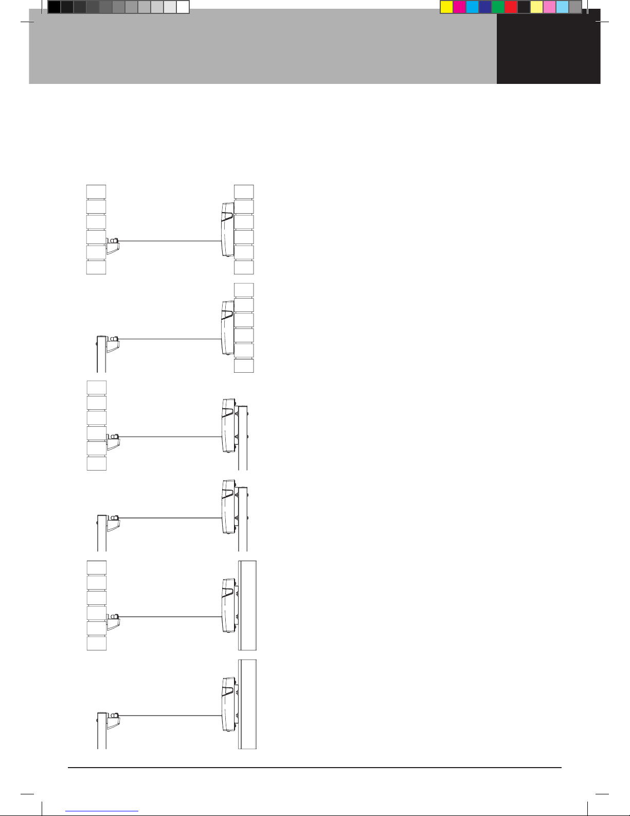
3Mounting Options
Determinewhichofthesixmountingoptionsmostsuit
your requirements.
Note:
MINIMUM operating distance is 2.0m (6'6")
MAXIMUM operating distance is 6.5m (21'4")
Masonry Wall to Post
Requires:PostKitx1
Masonry Wall to Masonry Wall
Post to Masonry Wall
Requires:PostKitx1,MountPlatex1
Post to Post
Requires:PostKitx2,MountPlatex1
Stud Wall to Masonry Wall
Requires:MountPlatex1
Stud Wall to Post
Requires:PostKitx1,MountPlatex1
HLS0046_4-6 line_Owners Manual_v6.indd 3 1/07/13 5:16 PM

4Step 1 - Select a suitable location
1.1 Select a suitable location for either wall or
post-mounted installations.
1.2 This product has been designed to mount and
operate between 2.0m (6'6") and up to 6.5m (21'4").
1.3 Alwaysleaveapproximately1.0m(3'3")clearanceeach
side of the line and any wall fence/shed etc.
1.4 Thereceivingbracketshouldbelocatedataheight
to ensure the extended lines are close to horizontal.
Note: This product must only be installed on sound structural walls.
Donotmountdirectlyontocladdingmaterials.Ifyouhaveanydoubt,
contactyourlocalhardwarestoreorinstallerforspecialistadvice.
Where possible, line height should
be user’s height + 5cm (2")
1.0m (3'3") clearance from
obstruction either side
2.0m (6'6") MINIMUM
6.5m (21'4") MAXIMUM
HLS0046_4-6 line_Owners Manual_v6.indd 4 1/07/13 5:16 PM
5
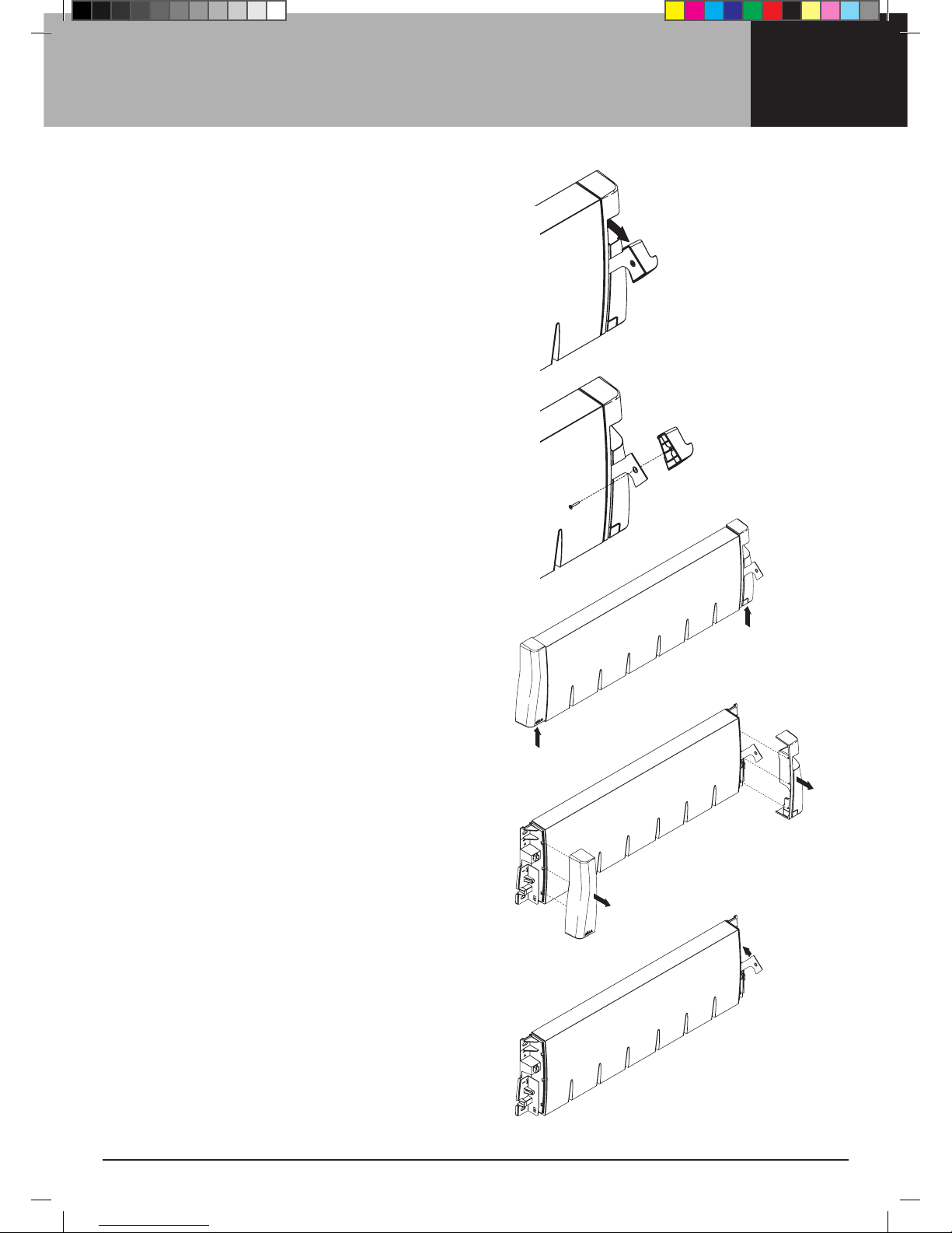
2.3 PushtheEndCoversapproximately5mmupward.
2.4 RemovetheEndCoversfromthecabinet.
SlidetherighthandsideCoverovertheLeverArm.
2.5 RotatetheLeverArmbackintothecabinet.
Your unit is now ready to be mounted.
Step 2 - Before you mount the cabinet
2.1 RotatetheLeverHandleoutwardfromthecabinet.
2.2 RemovetheLeverHandleandScrewfromthe
LeverArmusingaPhillipsheadscrewdriver.
HLS0046_4-6 line_Owners Manual_v6.indd 5 1/07/13 5:16 PM

6Step 3 - Mounting your cabinet
3A MOUNTING YOUR CABINET TO A MASONRY WALL
3a.1 Determinethebestlocationfortheinstallationofyour
product.ADrillingTemplateissuppliedtoassistyouwith
marking out the fastener hole locations. Line height
indicatorsandcentrelinesarealsoshownontheDrilling
Templateforboththecabinetandreceivingbracket.Mark
out a centre line for your product within your allocated site.
3a.2 Determinethecabinetlocation.Ensurethateither
side of this centre line and the area where the cabinet
is to be installed on the wall is free from pipes and
other obstructions.
3a.3 Mark the cabinet centre on the wall and temporarily
securetheDrillingTemplatetothewallusingtapeatthe
desiredheight.Useaspiritleveltoensurethatthecabinet
islevel.
3a.4 AlignthecentreoftheDrillingTemplatewiththeproposed
ReceivingBracketlocation.Ensurethattheprojected
centre line is perpendicular to the wall.
Note: DeterminethelineheightfromtheReceivingBracket
beforedrillingholes.IfmountingtheReceivingBracketto
anAdjustablePostKitrefertoFig. 3a and the Adjustable
PostKitinstallationmanual.
Line height
Centre line
Note: MAX line height when mounting
ReceivingBrackettoaPostis2metres.
LineheightofReceivingBracket=
height to top of post - (subtract) 2.5cm (1").
Fig. 3a
HLS0046_4-6 line_Owners Manual_v6.indd 6 1/07/13 5:16 PM
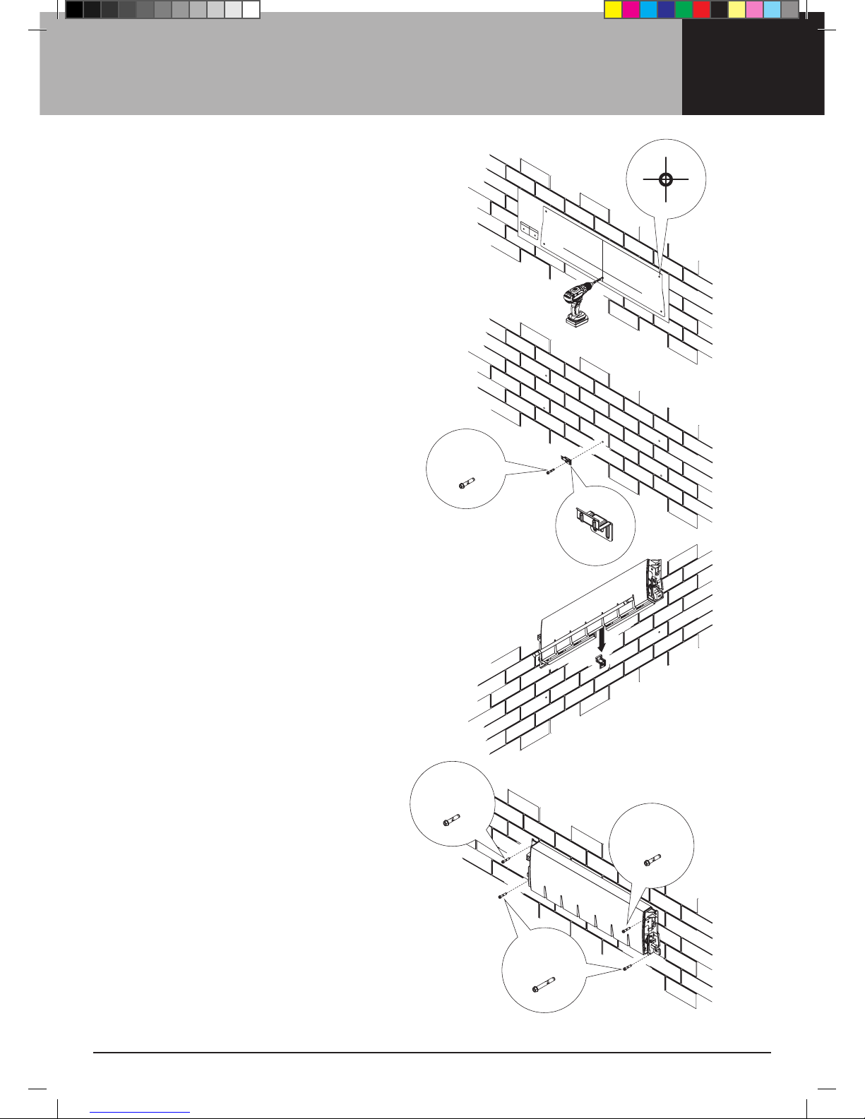
7
3a.5 Masonry fasteners are not included
with this product. When attaching to a
sound masonry wall, 5 x 10mm (13/32")
diametermasonrysleeveanchorsare
recommended.
Drill5holesusinga10mm(13/32")
masonry drill where marked on the
RetractingLineDrillingTemplate.
3a.6 RemoveDrillingTemplate.
3a.7 SecurelyfastentheCentreMountBracket
tothewallusingamasonrysleeveanchor
and using the centre hole.
3a.8 Using the Arm Handles (refer to 8.1 and
8.2 on page 15) lower the Arm and pull
it to the front of the cabinet. This is to
exposetheundersidecavity.
3a.9 Carefully position the cabinet against the
wallandabovetheCentreMountBracket.
Alignthecavityattherearofthe
underside of the cabinet with the Centre
MountBracket.Carefullylowerthecabinet
ontotheCentreMountBracket.
Note:TheCentreMountBracketwill
capture the products internal frame and
will assist in supporting the cabinet while
the next step is carried out.
3a.10 Insertmasonrysleevefastenersinthe
remaining 4 holes and tighten securely.
3a.11 Return the Arm to its original position
within the cabinet.
3a.12 Follow Step 4 on page 11 to complete
installation of the cabinet.
Ø10 x 55mm
Ø10 x 55mm
Ø10 x 55mm
Ø10 x 75mm
HLS0046_4-6 line_Owners Manual_v6.indd 7 1/07/13 5:16 PM

8Step 3 - Mounting your cabinet
3B MOUNTING YOUR CABINET TO A STUD WALL
3b.1 YouwillrequireaMountPlatetosecurelyfixyourcabinet
toastudwall.Determinethebestlocationforthe
installation of your product.
3b.2 Locate two stud centres and mark out a centre line for
your product within your allocated site.
3b.3 Determinethecabinetlocation.Ensurethateither
side of this centre line and the area where the cabinet
is to be installed on the wall is free from pipes and
other obstructions.
3b.4 MarktheMountPlate(andcabinet)centreonthewall.
Refer to Fig. 3bandtheMountPlateproductmanual.
3b.5 AlignthecentreoftheMountPlatewiththeproposed
ReceivingBracketlocation.Ensurethattheprojected
centre line is perpendicular to the wall.
Note:DeterminethelineheightfromtheReceivingBracket
beforefixingtheMountPlate.IfmountingtheReceiving
BrackettoanAdjustablePostKitrefertoFig. 3b and the
AdjustablePostKitinstallationmanual.
Line height
Centre line
8cm (3")
Stud centres
Fig. 3b
Note: MAX line height when mounting
ReceivingBrackettoaPost
is 2.0 metres (6'6").
LineheightofReceivingBracket=
height to top of post - (subtract) 2.5cm (1").
Lineheightofcabinet=
heighttobottomofMountBracket+8cm(3").
HLS0046_4-6 line_Owners Manual_v6.indd 8 1/07/13 5:16 PM

9
17.5cm (7")
3C MOUNTING YOUR CABINET TO A POST
3c.1 YouwillrequireonePostKitandoneMountPlate.
Determinethebestlocationfortheinstallationofyour
product.Determineyourcabinetpostlocationandmark
out a centre line for your product within your allocated site.
3c.2 AssembleyourMountPlate,CentreMountBracketand
PostKit,anddeterminethecabinetlineheight.Referto
Fig. 3c,thePostKitinstallationmanualandtheMount
Plateinstallationmanual.
3c.3 AlignthecentreoftheMountPlatewiththeproposed
ReceivingBracketlocation.Ensurethattheprojected
centrelineisperpendiculartotheMountPlate.
Note:Determinetheproposedlineheightfromthecabinet
before cementing a post into the ground.
Line height
Centre line
Fig. 3cNote: MAX line height when mounting
cabinettoaMountBracketand
Adjustable Postis1.8metres(5'11").
Lineheightofcabinet=
top of post - (subtract) 17.5cm (7").
HeightofReceivingBracketpost=
Line height + 2.5cm (1").
HLS0046_4-6 line_Owners Manual_v6.indd 9 1/07/13 5:16 PM

10 Step 3 - Mounting your cabinet
3D MOUNTING YOUR CABINET TO A MOUNT
PLATE (WALL OR POST NOT ILLUSTRATED)
3d.1 FixtheCentreMountBrackettotheMountPlate
through the centre hole using the fasteners
providedbeforeassemblingtheMountPlatetoa
wallorpost.Pleasenotethescreworientation.
3d.2 SecurelyfastentheMountPlatetoastudwallor
post.RefertotheMountPlateproductmanual
and Step 3b (page 8) or Step 3c (page 9).
3d.3 Lower the Arm on the cabinet and pull it to the
front of the cabinet.
Carefully position the cabinet against the front
faceoftheMountPlateandabovetheCentre
MountBracket.
Alignthecavityattherearoftheundersideofthe
cabinetwiththeCentreMountBracket.Carefully
lowerthecabinetontotheCentreMountPlate.
Note:TheCentreMountPlatewillcapture
the product’s internal frame and will assist in
supporting the cabinet while the next step is
carried out.
3d.4 Usetheremainingfastenersprovidedwiththe
MountPlatetosecurelyfixthecabinettothe
MountPlate.
3d.5 Follow Step 4 on page 11 to complete
installation of the cabinet.
M8 x 20mm
M8 x 20mm
M8 x 30mm
HLS0046_4-6 line_Owners Manual_v6.indd 10 1/07/13 5:16 PM
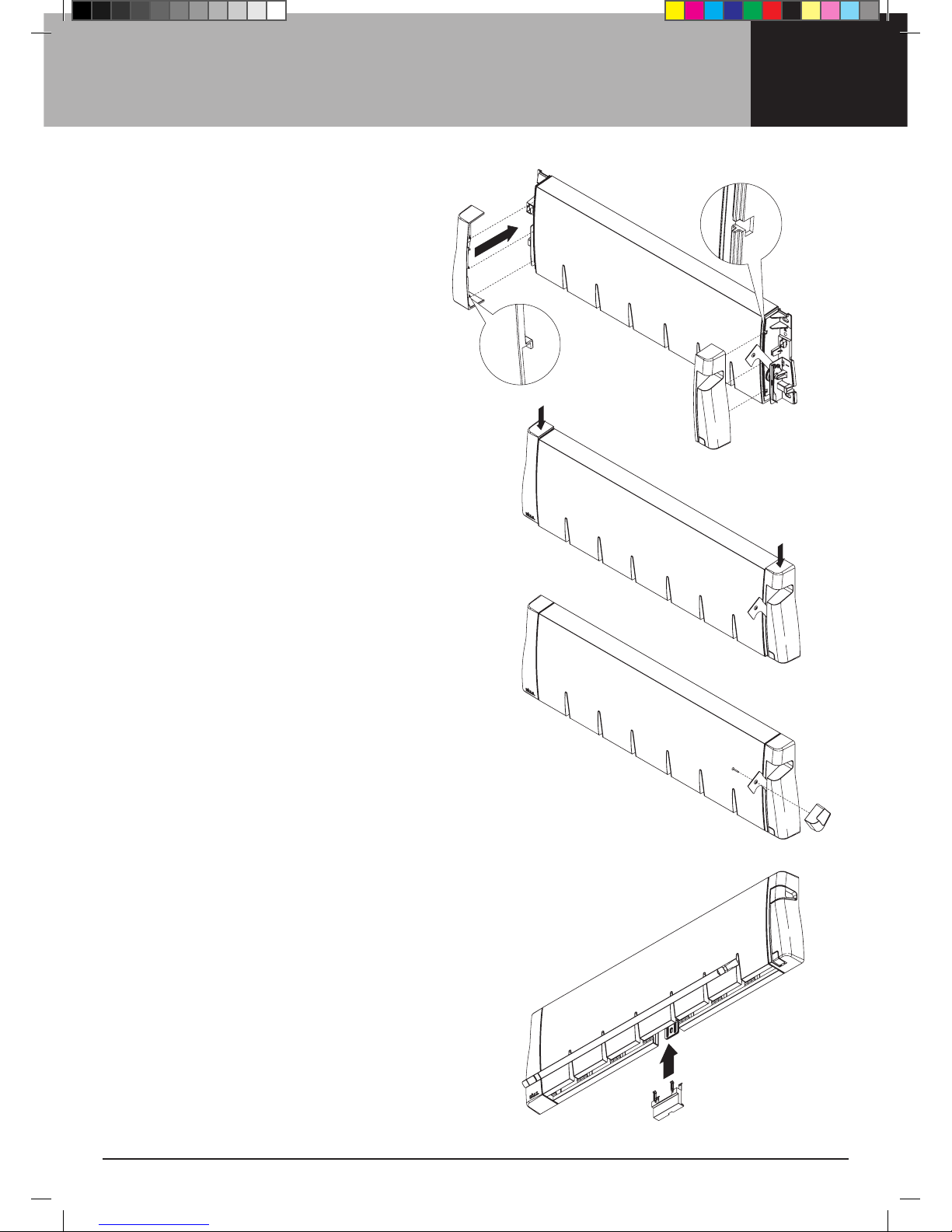
11
4.1 RotatetheLeveroutwardslightlyandfeedtheLever
throughtheslitintherighthandsideEndCover.
AlignthehooksontheEndCoverswiththeslotson
thecabinet.PushtheEndCoversontothecabinet
so that the hooks sit within the slots.
4.2 PushtheEndCoversdownwardtofullyengagethe
hooks. The top and front surfaces of the cabinet
shouldsitflushwiththeEndCovers.
4.3 ReplacetheLeverHandleandscrew.
4.4 Using the Arm Handles (refer to 8.1 and 8.2 on
page 15) lower the Arm and pull it to the front of the
cabinet.Thisistoexposetheundersidecavity.
4.5 SnaptheCentreMountCoverintopositionwithin
thecavityattherearoftheundersideoftheunit.
TheCovershouldsitflushwiththesurrounding
surfaces of the cabinet.
4.6 Return the Arm to its original position within
the cabinet.
Step 4 - Replacing Covers and Lever Handle
HLS0046_4-6 line_Owners Manual_v6.indd 11 1/07/13 5:16 PM
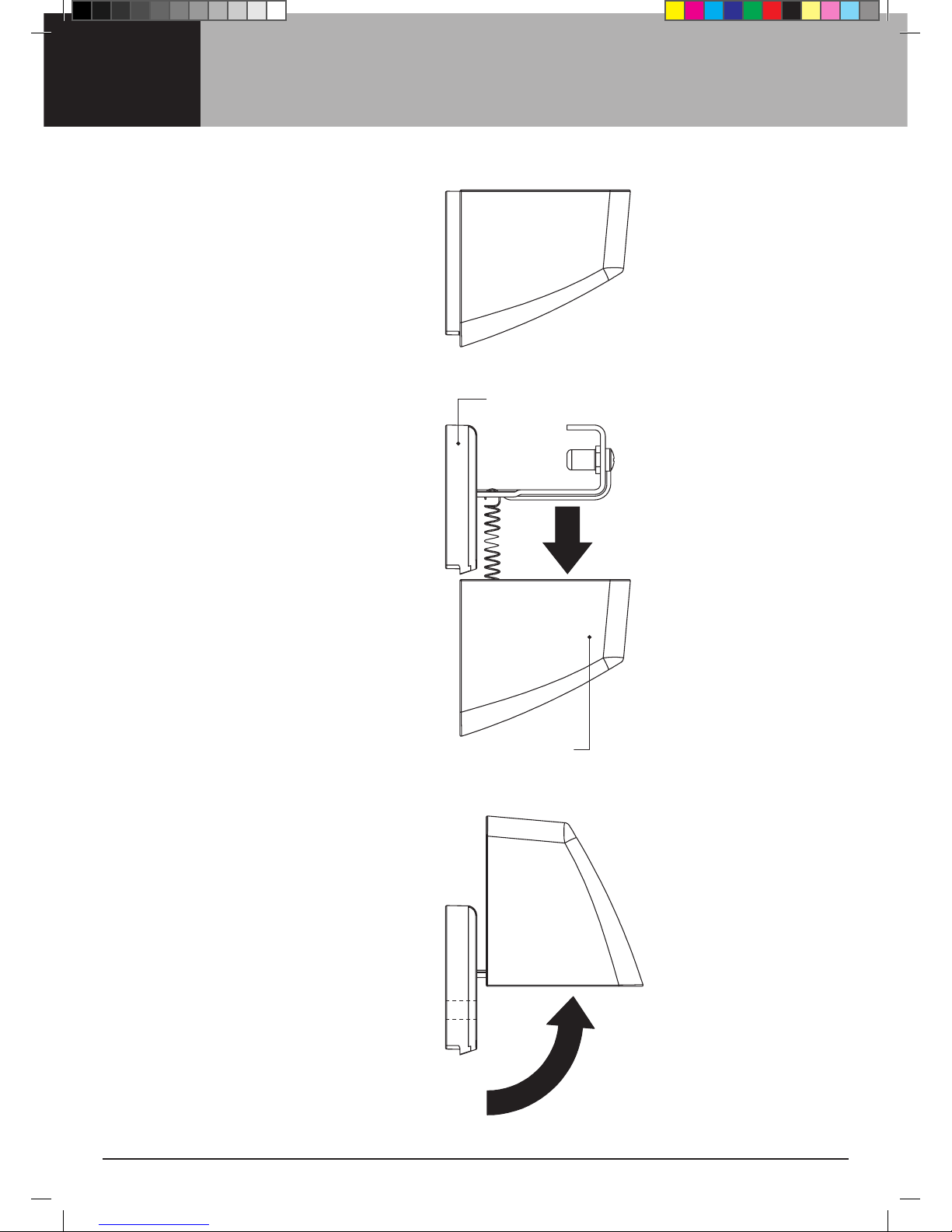
12 Step 5 - Preparing Receiving Bracket for mounting
5.1 BeforeyoumounttheReceiving
Bracketthereareacoupleof
quick steps to follow to expose
the mount holes.
5.2 WhileholdingthetopoftheBacking
Plate,pulltheOuterCoverdownward
andpasttheBackingPlate.
Note: Care should be taken to not
over-extendthe springs.
Do not release the outer cover
quickly as this may lead to
personal injury, property or
product damage.
5.3 RotatetheOuterCoverupwardto
expose the mount holes.
BackingPlate
OuterCover
HLS0046_4-6 line_Owners Manual_v6.indd 12 1/07/13 5:16 PM
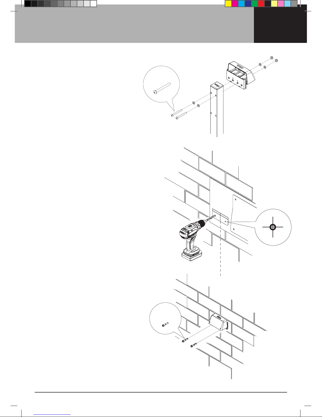
13
Step 6 - Mounting the Receiving Bracket
6A MOUNTING YOUR RECEIVING
BRACKET TO A POST
6a.1 Using the fasteners supplied with
yourPostKitattachtheReceiving
Bracketasshown.
6B MOUNTING YOUR RECEIVING
BRACKET TO A MASONRY WALL
6b.1 Use the centre line and line height
indicators displayed on the drilling
templatetoaligntheReceiving
Bracketwiththecabinet.
6b.2 Align and temporarily secure the
DrillingTemplatetothewallusing
tape at the desired height.
6b.3 Drill2holesusinga10mm(13/32”)
masonry drill where marked on the
RetractingLineDrillingTemplate.
6b.4 RemovetheDrillingTemplate.
6b.5 PositiontheReceivingBracketon
the Wall and align the mount holes
with the drilled holes.
6b.6 Insertmasonrysleevefastenersin
the 2 holes and tighten securely.
M8 x 70mm
Ø10 x 55mm
HLS0046_4-6 line_Owners Manual_v6.indd 13 1/07/13 5:16 PM
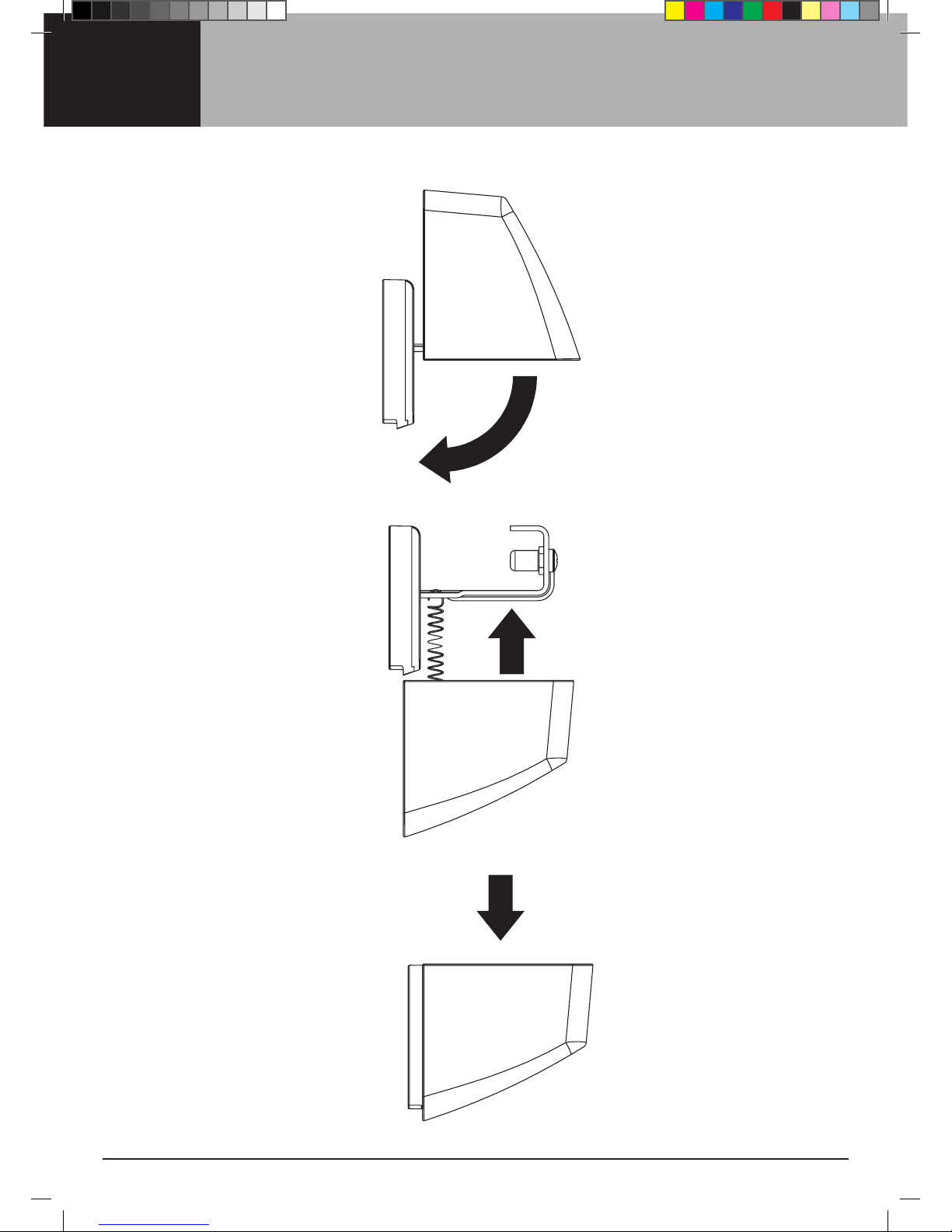
14 Step 7 - Preparing Receiving Bracket for Operation
7.1 RotatetheOuterCoverdownward.
7.2 AligntheOuterCoverinternalslots
withBackingPlateouterribs.Slide
theCoverontotheBackingPlateand
allowtheCovertoreturntothetop
position.JiggletheCovertofreeit
should it not slide smoothly.
7.3 PushtheCoverdownwardand
allow it to spring upward to test
its operation.
HLS0046_4-6 line_Owners Manual_v6.indd 14 1/07/13 5:16 PM

15
Step 7 - Preparing Receiving Bracket for Operation
Step 8 - Operation
8.1 To extend the arm and line assembly
Arm Handles from the underside of
the cabinet.
8.2 PullArmandLinesdownwardfromthe
cabinet using the Arm Handles.
8.3 PullArmandLineshorizontally
forward from the cabinet towards the
ReceivingBracket.
HLS0046_4-6 line_Owners Manual_v6.indd 15 1/07/13 5:16 PM

16 Step 8 - Operation
8.7 Tensioning the Lines
Therearetwotensionsettingsthatprovidetaught
LineatvariousLineextensiondistances.
Position 1 - 2.0m to 4m of line extension
SlowlyrotatetheLeverHandledownwarduntilyou
feel and/or hear a click.
Position 2 - 4 to 6.5m of line extension
SlowlyrotatetheLeverHandledownwardpast
Position1untilyoufeeland/orhearasecondclick.
8.4 Engaging the Arm and Line assembly in the
Receiving Bracket
Lower the Arm onto the
ReceivingBracketbetweenthe
two centre Lines.
8.5 SeattheArmwithintheReceivingBracket.Allowthe
Arm and Lines to slide back towards the cabinet and
engageonthetwoLockingPinswithintheReceiving
Bracket.
Note: Two holes in the centre of the Arm must
engagewiththeReceivingBracketLockingPins.
8.6 WiththeArmsecurewithintheReceivingBracket,
youmaynowtensiontheLinesusingtheLever
on the cabinet.
Position 1 Position 2
HLS0046_4-6 line_Owners Manual_v6.indd 16 1/07/13 5:16 PM

17
Handy Hints
When hanging thick or bulky items, lay
themovermorethanoneLine.
When you don’t expect to fill the capacity
of your clothesline, hang your clothes on
the outer Lines, as this will allow clothes to
dry more easily.
8.8 Releasing Line tension
The following images show releasing Line tension
fromPosition1.Applythesameactionstorelease
LinetensionfromPosition2.
8.8a RotatetheLeverHandledownardslightlyandhold.
8.8b WhileholdingtheLeverHandledownwardpress
and hold the button.
8.8c Whilepressingthebutton,allowtheLeverhandle
toslowlyrotateupward.PositiontheLeverHandle
back within the cabinet.
WARNING: The Lines are under spring tension.
DonotallowtheArmandLinestoretractuncontrolled
as this may lead to personal injury, property or
product damage. Hold the Arm securely and walk
it back to the cabinet.
Care and Maintenance
Regularly inspect all components and check for wear and tear or damage.
Ensure fasteners are secure. If there is any damage, parts should be replaced
with original Hills spares. The Clothesline should be repaired before using again.
Your Clothesline should be periodically wiped clean with a damp cloth and
mild detergent.
Wedonotrecommendtheuseofoilor‘WD’typelubricantsonanypartof
the Clothesline.
To maintain appearance and durability of coatings on metal components we
recommend a twice yearly application of a reputable brand of car polish or wax.
Step 8 - Operation
Button
HLS0046_4-6 line_Owners Manual_v6.indd 17 1/07/13 5:16 PM

18 Warranty
DesignedandtestedunderaQualitySystemthatmeetsHills
demanding quality specifications ® Hills Warranty.
1. Hillsprovidesconsumerswiththefollowingwarrantyinrelation
tothisProduct,inadditiontocomplyingwiththerequirements
ofanyrelevantlegislation,includingtheCompetitionand
Consumer Act 2010 (Cth) in Australia and the Consumer
Guarantees Act 1993 in New Zealand (the Acts), except where
aNewZealandconsumeracquirestherelevantProductforthe
purposes of a business.
2.Inthiswarranty,wehaveusedthefollowingdefinitions:
(a) Hills, our or wemeansHillsHoldingsLimited(ABN35007
573417)of159PortRoadHindmarshSouthAustralia5007;
(b) Products means the following goods manufactured by
Hills (including products manufactured for Hills by its
contract manufacturers): Hills Slim Retracting Clothesline;
(c) Material means a material or component used by Hills in
themanufactureoftheProducts;
(d) Warranty Period means 10 years from the date of
purchaseoftherelevantProductand,inrelationtothe
polycore line, means a period of 1 year from the date of
purchaseoftheProduct.IftheProductorpart(asthecase
may be) is repaired or replaced, there will be no extension to
theoriginalwarrantyperiod;and
(e) Workmanship means the handling, assembly and
manufacturing processes performed by or on behalf of
HillsinordertomanufacturetheProducts.
3.HillswarrantsthatforthedurationoftheWarrantyPeriod,
allProductswillbefreeoffaultsarisingfromdefectsin
Workmanship or Materials, on the terms and conditions set
out in this warranty.
4.HillsundertakesthatifduringtheWarrantyPeriodanyProduct,
oranypartofaProduct,hasfailedtooperatecorrectlydueto
faultyWorkmanshipordefectiveMaterial,itwillrepairorreplace
theProductorpart(asthecasemaybe)freeofchargeprovided
that the following procedure is met:
(a) The consumer must contact Hills upon becoming aware of
anydefecttoaProduct.ThecontactdetailsforHillsareset
outinthiswarrantyandundertheheading“HillsContacts”.
(b) Following consultation with Hills, Hills will determine whether
there is a defect, and if so Hills agrees to (at Hills’ option):
i.inthecaseofgoods–repair,replaceorsupplyequivalent
goods, or pay the cost of any of those remedies to the
consumer;or
ii.inthecaseofservices–supplytheservicesagainorpay
thecostofhavingtheservicessuppliedagain.
(c) IfHillsrequeststhereturnoftheapplicableProductorpart,
Hills will be responsible for the collection and freight costs
ofreturningthatProductorpart.Theconsumeragreesto
assist Hills with any reasonable request to enable Hills to
collectsuchProductorpart.
(d) Hills also agrees to be responsible for the freight costs to
deliveranynewProductorreplacementparttotheconsumer.
5. This warranty is in addition to any non-excludable legal rights
or remedies conferred on the consumer under any applicable
Act and any similar laws. To the extent permitted by law, Hills’
liability for any non-excludable condition or warranty is limited to
rectifying any defect at its option, as set out in paragraph 4(b).
6. Subject to the requirements of any applicable Act or legislation
and to the extent permitted by law, no liability (whether
expressedorimplied)ofanynaturewhatsoever,isacceptedby
Hills for any consequential loss, damage or injury arising as a
resultofanyfaultintheProducts.
7. ThiswarrantydoesnotextendtodamagetoProductswhich
occurs during transit or transportation, or which is caused
by any abuse, accident or improper installation, connection,
use, adjustment or repair or use of goods otherwise than in
accordance with instructions issued by Hills.
8. ThewarrantyonProductsiswaivedifanyadditionor
attachmenttotheProductsdonothaveHills’specificapproval
orarenotsoldasHillsproducts.TheProductsaredesigned
to perform specific tasks under established test loads and
unauthorised attachments may produce stresses for which the
design is not appropriate.
9.Thefollowingappliestoconsumerswhopurchasedarelevant
ProductinAustralia:
Ourgoodscomewithguaranteesthatcannotbeexcluded
under the Australian Consumer Law. You are entitled to a
replacement or refund for a major failure and compensation
for any other reasonably foreseeable loss or damage. You
arealsoentitledtohavethegoodsrepairedorreplacedifthe
goods fail to be of acceptable quality and the failure does not
amount to a major failure.
HLS0046_4-6 line_Owners Manual_v6.indd 18 1/07/13 5:16 PM

19
Hills Contacts
Wearecommittedtoprovidingyouwith
completecustomersatisfaction.Ifyouhave
any questions or comments about our
productsorservicespleasecontactyour
nearestCustomerServiceCentreduring
their local business hours:
Australia
1300 300 564
New Zealand
09 262 3052
Rest of the World
Refer to Hills Website
www.hills.com.au/en/contact-us
Hills Websites
www.hills.com.au
HillsBrandedProducts
www.hills.com.au/customerservice
HillsConsumerAdvice
www.hillsholdings.com.au
Hills Holdings Limited
HLS0046_4-6 line_Owners Manual_v6.indd 19 1/07/13 5:16 PM

Hills Holdings Limited
A.B.N.35007573417
Issue July 2013
PD4654a
HLS0046_4-6 line_Owners Manual_v6.indd 20 1/07/13 5:16 PM
This manual suits for next models
1
Table of contents
Other Hills Personal Care Product manuals


