Hills extenda 4 User manual
ExtendaTM 4 and
ExtendaTM 6
Retracting Clothesline
Owner’s Manual
2
Congratulations
Congratulations on the purchase of your new Hills®Retracting Clothesline, which will
bring you many years of trouble free and efficient drying.
It is important that you read this Owner’s Manual thoroughly before installation and use.
In this way you will benefit from all the design features and enjoy safe use of the product.
Thank you for choosing Hills.
Warning
• DonotallowchildrenorpetstoswingontheClotheslineoritemsoflaundry.
• Donotuseforanypurposeotherthantohanganddrywashing.
• DonotuseyourClotheslineifpartsarewornordamaged.
• Donotoperatethelockingleverwhenthearmislocatedinthecabinet.
• Donotreleasethelockingmechanismwhenthereareclothesattachedtothelines.
• Donotallowthearmandlinestoretractuncontrolledasthismayleadtopersonal
injury or property damage. Hold the arm securely and walk it back to the cabinet.
• Patentsandregistereddesignsapplytothisproduct.
Carton Contents
ExtendaTM 6
Part name Qty.
ExtendaTM 6 cabinet 1
Receivingbracket 1
Introduction
ExtendaTM 4
Part name Qty.
ExtendaTM 4 cabinet 1
Receivingbracket 1

3
Optional Mounting Kits
Post Mount Kits
IfyouchoosetomountyourRetractingClotheslinecabinetorreceivingbracketonposts,
thefollowingproductsareavailable.
Post Kits:
FD51044–AdjustablePostKit
Mount Bar Kits:
FD51070–MountBar(ExtendaTM 6)
FD51072–MountBar(ExtendaTM 4)
4
Mounting Options
Mounting Options
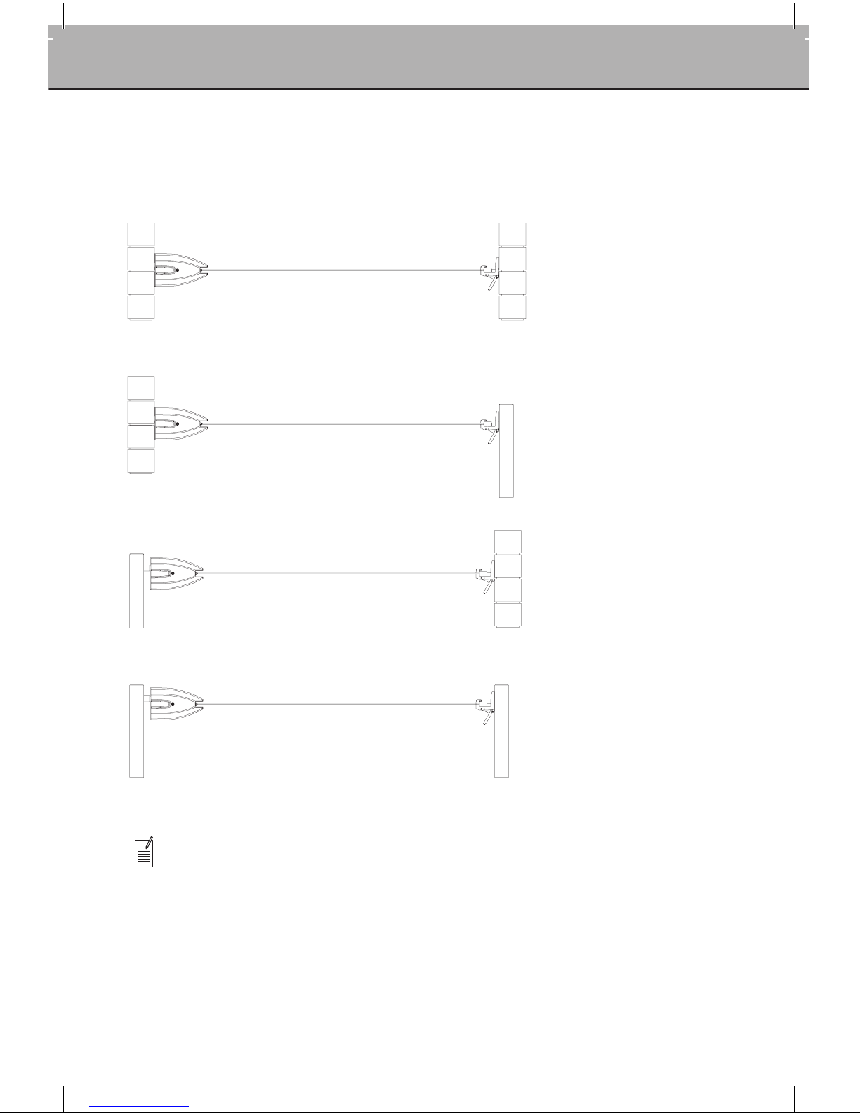
Determinewhichofthefourmountingoptionsmostsuitsyourrequirements.
Wall to Wall
Wall to Post
Requires:
1PostKit
Post to Wall
Requires:
1PostKit
1MountBarKit
Post to Post
Requires:
2PostKits
1MountBarKit
Note:Minimumoperatingdistanceis4m(13’).
Maximumoperatingdistanceis6.5m(21’4”)
5
Site Selection
Step 1 - Select a suitable location
1.1 Select a suitable location for either wall or post mounted installations.
1.2 Thisproducthasbeendesignedtomountandoperatebetween4m(13’)and
upto6.5m(21’4”).
1.3 Alwaysleaveapproximately1.5m(5’)clearanceeachsideofthelineandanywall
fence/shed etc.
Note: This product must only be installed on sound structural walls.
Donotmountdirectlyontocladdingmaterials.
Ifyouhaveanydoubt,contactyourlocalhardwarestoreorinstaller.
1.5m(5’)clearancefrom
obstructions either side
Receivingbracket
Cabinet
4m(13’)minimum
6.5m(21’4”)maximum
Mounting surface
Arm
Mounting surface
6
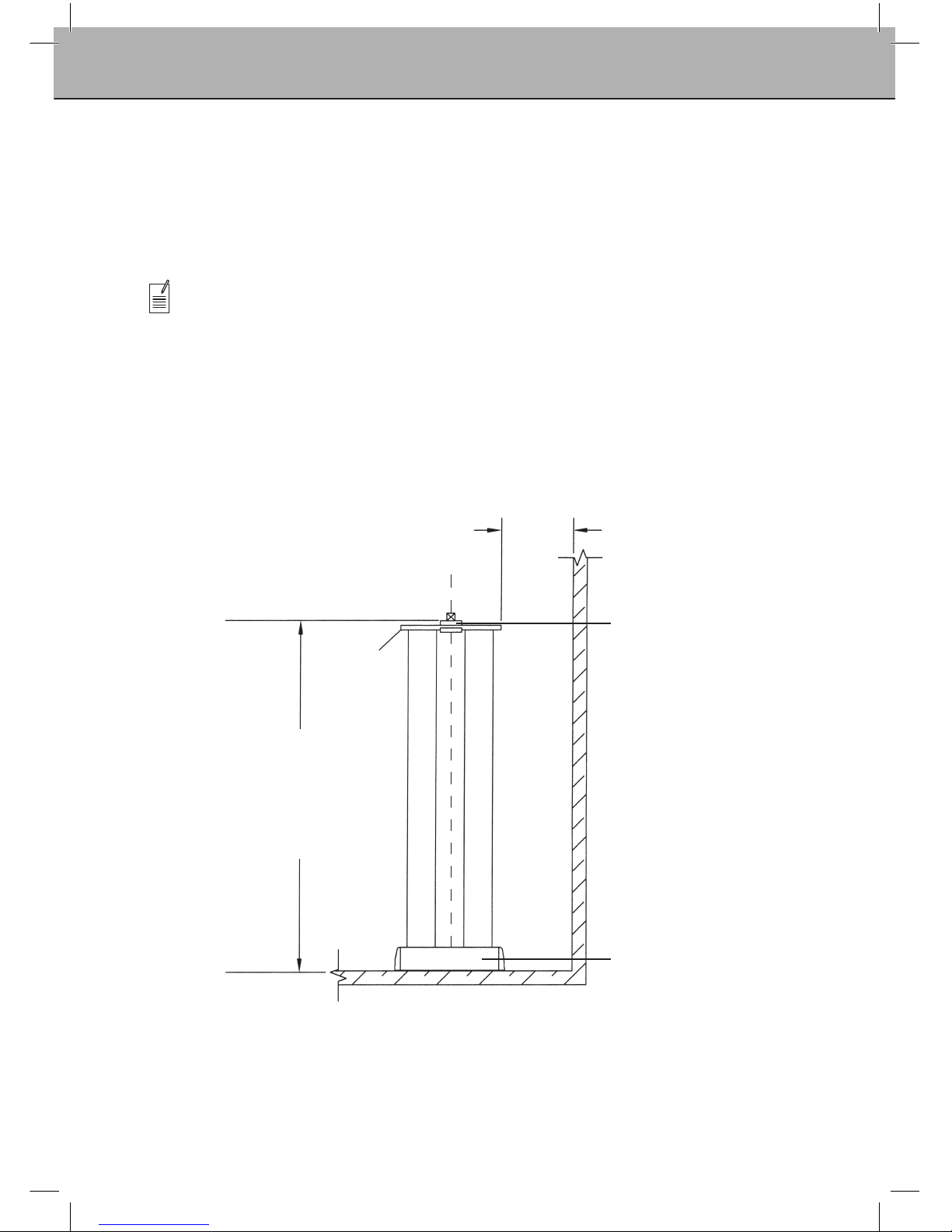
Cabinet
fasteners
Location of cabinet
fasteners are approximately
75mm(3”)aboveuser’s
head height.
User’s head height
50mm(2”)75mm(3”)
115mm
(41/2”)
125mm
(5”)
Receiving
bracket
fasteners
Locationofreceivingbracket
fastenersareapproximately85mm
(31/2”)aboveuser’sheadheight
(wheninstalledonlevelground).
Note:thereceivingbracket
should be located at a height
to ensure the clothesline is
close to horizontal.
Cabinet
fasteners
Receiving
bracket
fasteners
Mount bar
Top of post
Postkit
For post mounting a cabinet,
the top of the post should be
approximately115mm(41/2”)
abovetheuser’sheadheight.
Forpostmountingareceiving
bracket, the top of the post
shouldbeapproximately125mm
(5”)abovetheuser’sheadheight
(wheninstalledonlevelground).
Note:thereceivingbracket
should be located at a height
to ensure the clothesline is
close to horizontal.
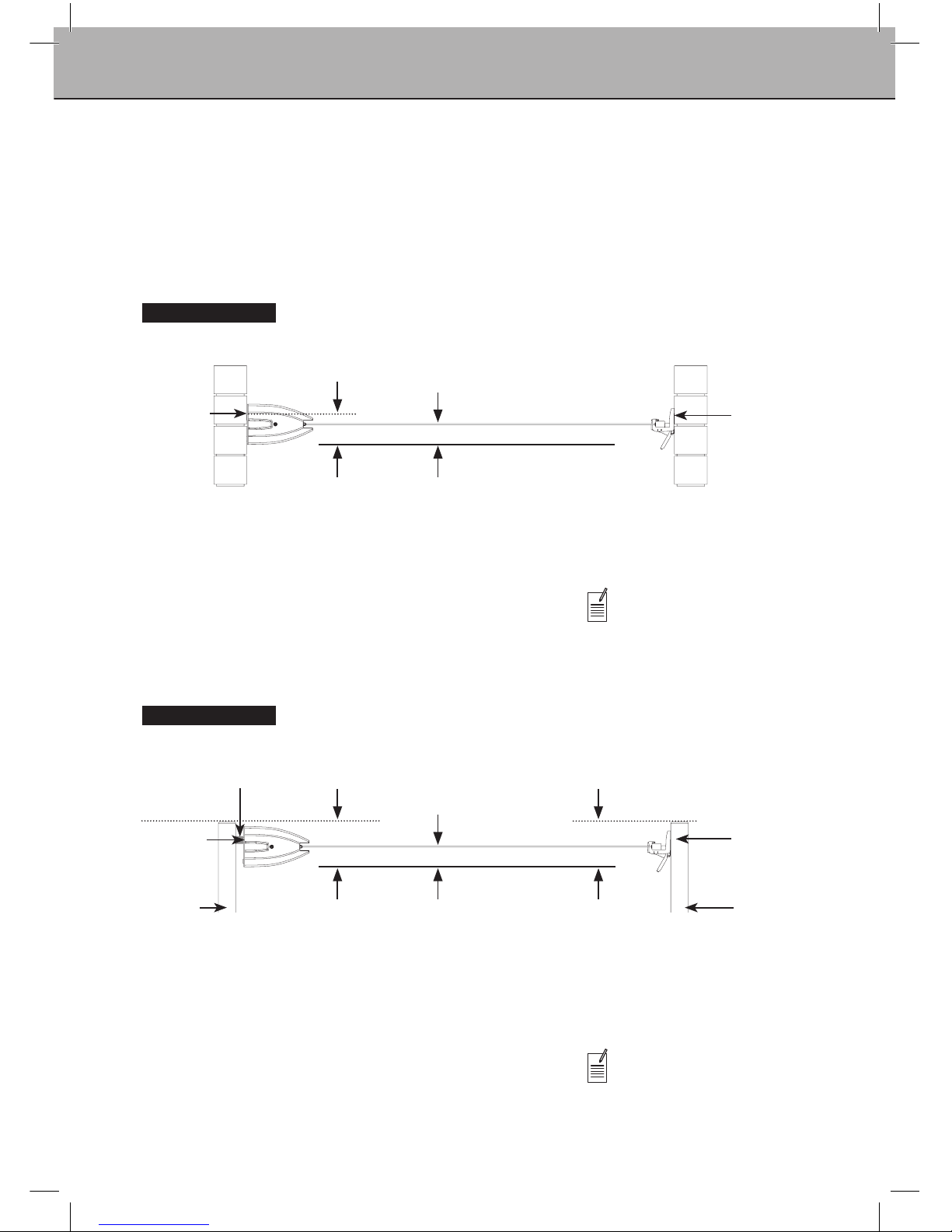
Installation Height
Wall Installation
Step 2 – Recommended installation height
2.1 For all installations, we recommend the operational height for the line is
approximately50mm(2”)abovetheuser’sheadheight.
2.2 For the heights and combinations of wall/post installations refer to the appropriate
details below.
User’s head height
50mm(2”)
Post Installation
Cabinet
Cabinet
Receiving bracket
Receiving bracket
Top of post
Postkit
7
Drill2holesusing
masonry drill
Productcentre
43mm
Mount hole centres
Top of
product
Productcentreline
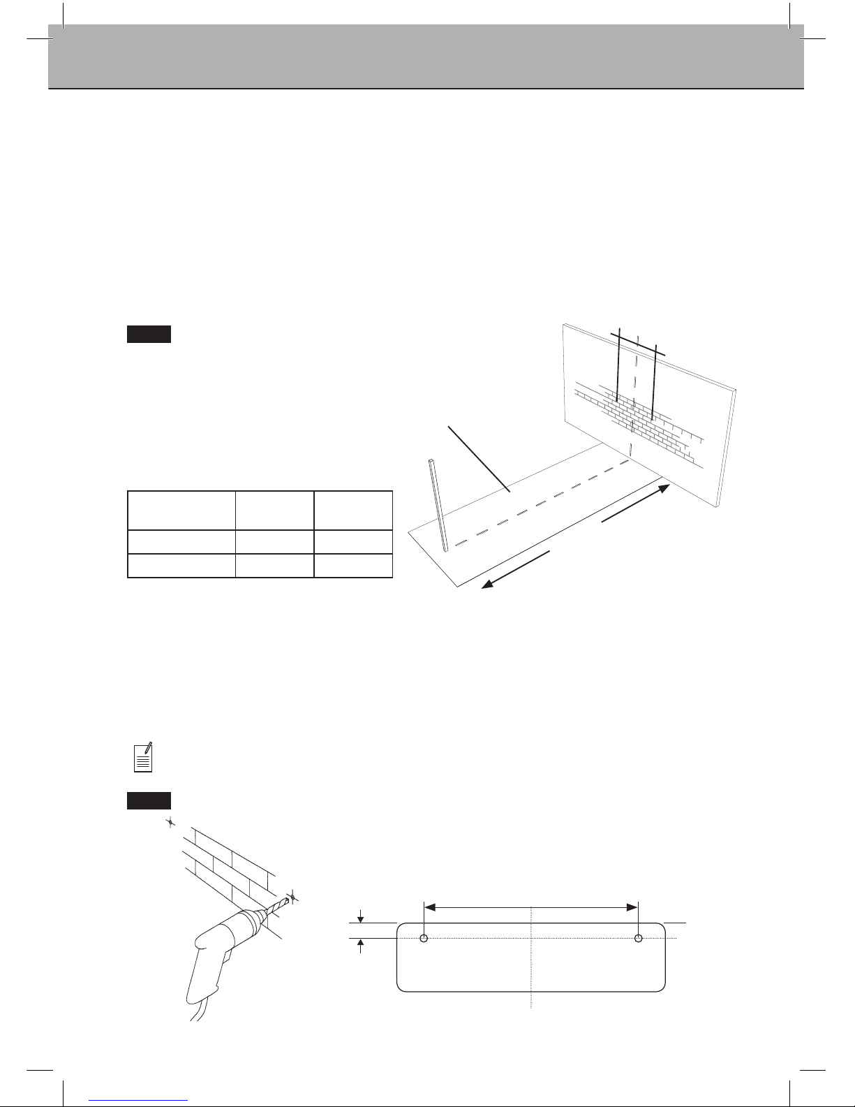
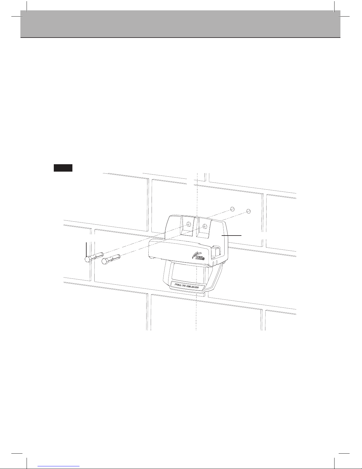
Step 3 – Mounting your cabinet to a wall
3.1 Prepare your cabinet location
Determinethebestlocationfortheinstallationofyourproduct(refertopage5).
Mark out a centre line for your product within your allocated site.
3.2 Ensure that either side of this centreline and the area where the cabinet is to be
installed on the wall is free from pipes and other obstructions (Fig. 1).
3.3 Markthecabinetmountcentresonthewallatthedesiredinstallationheight(refer
to page 6 and the table below).
‘Mount Hole Centres’
Product Centres
(mm)
Centres
(inch)
ExtendaTM 6 814 32
ExtendaTM 4 570 221/2
Fig. 1
Installation
3.4 Drill holes in wall
Masonry fasteners are not included with this product. When attaching to a sound
masonrywall,werecommendusingmasonrysleeveanchors(diameter10mmx
55mm).
3.5 Ifyouareusingthesefasteners,drillaø10mm(13/32”)holeusingamasonry
drill (Fig 2).
Note: If you are mounting to a different wall type, consult your hardware store for
adviceontheappropriatefastenerstouse.
Fig. 2
4m(13’)
to6.5m(21’4”)
Mount
centres
Ensure surrounding
area is free from
obstructions
8
Installation
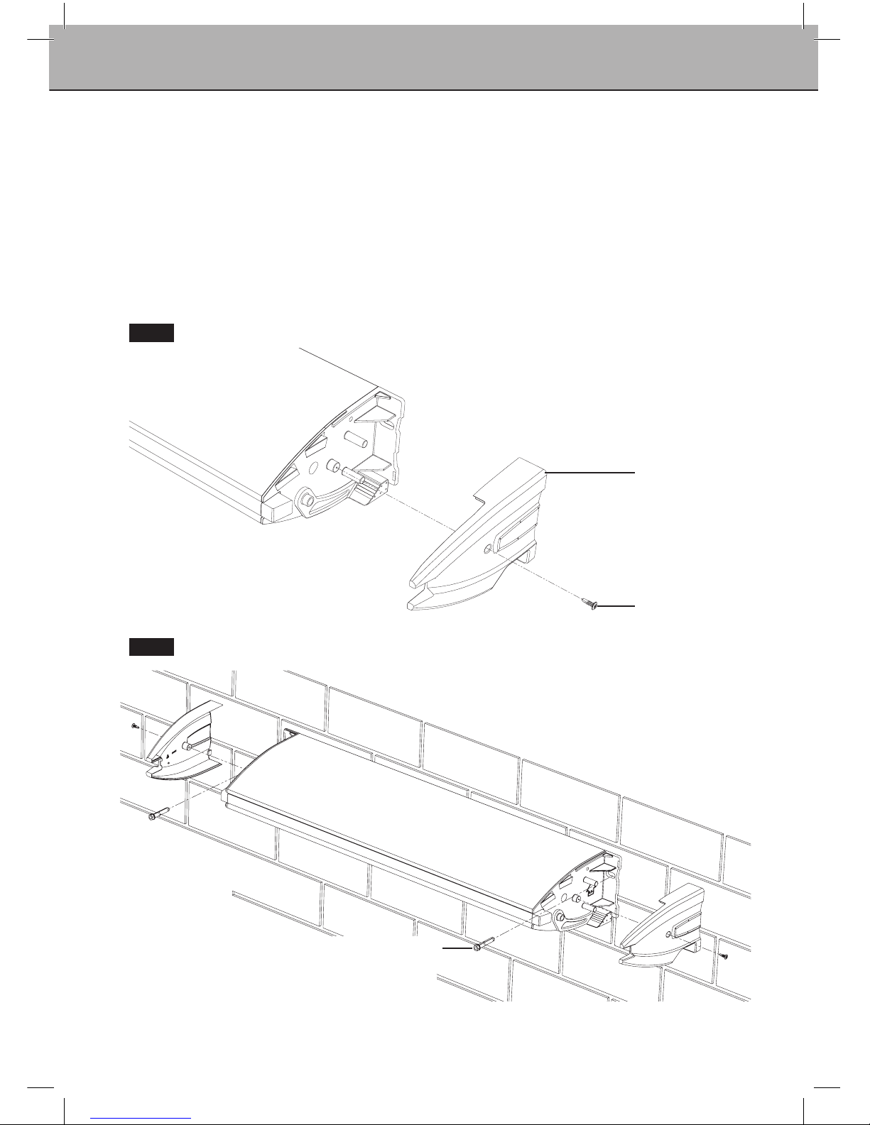
Step 3 (continued) – Mounting your cabinet to a wall
3.6 Secure your cabinet to the wall
Removetheendcoversusingaphillipsheadscrewdriver.(Fig. 3).
3.7 EnsuresquaremetallockingroddoesnotcomeoutoftheCabinet.
3.8 Locate the cabinet with the mount holes. Insert masonry fasteners
and secure (Fig. 4).
3.9 Re-attachcabinetendcovers(Fig. 4).Donotovertightenthescrews.
Fig. 3
Fig. 4
Endcover
Endcoverscrew
Masonry anchor
(Notincluded)
9
Step 4 – Mounting your cabinet to a post
4.1 Prepare your cabinet location
Determinethebestlocationfortheinstallationofyourproduct(refertopage5).
Mark out a centreline for your product within your allocated site.
4.2 Determineyourpostlocations.
Install as per the instructions supplied with your post kit.
Refer to diagram on page 6 to determine the installation height.
Refertopage3forthepostkitavailable.
4.3 To post mount your cabinet you will need to purchase a matching
mountbarkit(refertopage3).
4.4 Attachthemountbartothepostasperinstructionssuppliedwithyour
mount bar kit.
Fig. 5
Installation
Ensure surrounding area
is free from obstruction
Productcentreline
4m(13’)
to6.5m(21’4”)

10
Step 4 (continued) – Mounting your cabinet to a post
4.5 Securing your cabinet to a post
Removeendcoversusingaphillipsheadscrewdriver(Fig. 6).
4.6 EnsuresquaremetallockingroddoesnotcomeoutoftheCabinet.
4.7 Locatethecabinetwiththepre-drilledholesinthemountbar(soldseparately).
Usingthefastenersandinstructionsprovidedwiththemountbarkitsecurethe
cabinet to the post assembly (Fig. 7).
4.8 Reattachcabinetendcovers(Fig. 7).
Installation
Fig. 6
Fig. 7
Endcover
Endcoverscrew
Postkit
(soldseparately)
Cabinet
Endcover
Washer
Washer
M8 nyloc nut
M8x45socketheadbolt
Mount bar
(soldseparately)
11
Installation
Step 5 – Mounting your receiving bracket to a wall
5.1 Prepare your receiving bracket location
Mark the mount hole centres on your pre-determined centreline at the desired
height(refertopage6).Ensuretherearenopipesorobstructionsinthe
surrounding area.
5.2 Drill holes in the wall
Refertopage7forinstructionsondrillingholesandappropriatefasteners.
5.3 Securing your receiving bracket to the wall
Insertthemasonryfastenersandsecure(Notincludedwiththisproduct.)(Fig. 8).
Receivingbracket
Productcentreline
Masonry anchor
Fig. 8

12
Installation
Step 6 – Mounting your receiving bracket to a post
6.1 Prepare your receiving bracket location
On the pre-determined product centre, locate the position for your post and
receivingbracket.Refertopage5.
6.2 Install your post as per the instructions supplied with your post kit.
Refer to diagram on page 6 to determine the installation height of your post.
Refertopage3forthepostkitavailable.
6.3 Secure the receiving bracket to a post
Usingthefastenerssuppliedwithyourpostkitattachthereceivingbracket
to the post kit assembly (Fig. 9).
Fig. 9
Receivingbracket
Washer
Washer
M8 nyloc nut
Postkit
(soldseparately)
BoltM8x70socketheadbolt

13
Operation
Step 7 – Operation
WARNING: Do notoperatethelockingleverwhenthearmislocatedincabinet.
WARNING: Do not release the locking mechanism when there are clothes
attached to the lines.
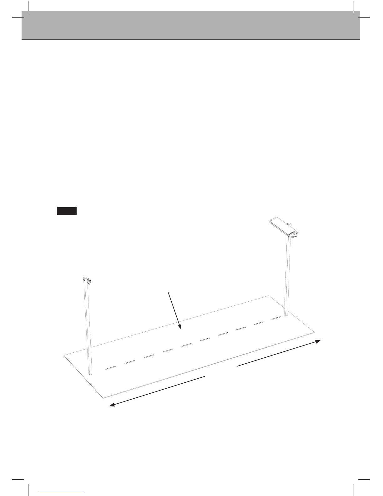
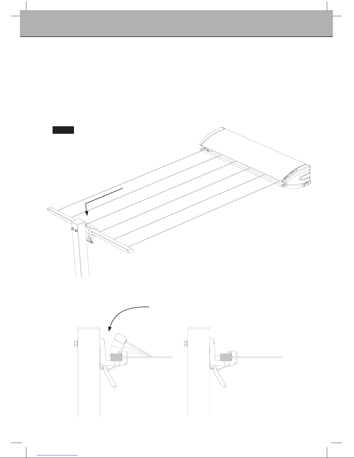
7.1 To extend the arm and line assembly
Removethearmfromthecabinetbypullingonthetwoblueendcaps.
Holdingthearmrmly,extendittowardsthereceivingbracket(Fig. 10).
Fig. 10
Pullbothendcapsto
removearmfromcabinet
Pullarmoutofcabinetandextend
towardsreceivingbracket
14
Operation
Step 7 (continued) – Operation
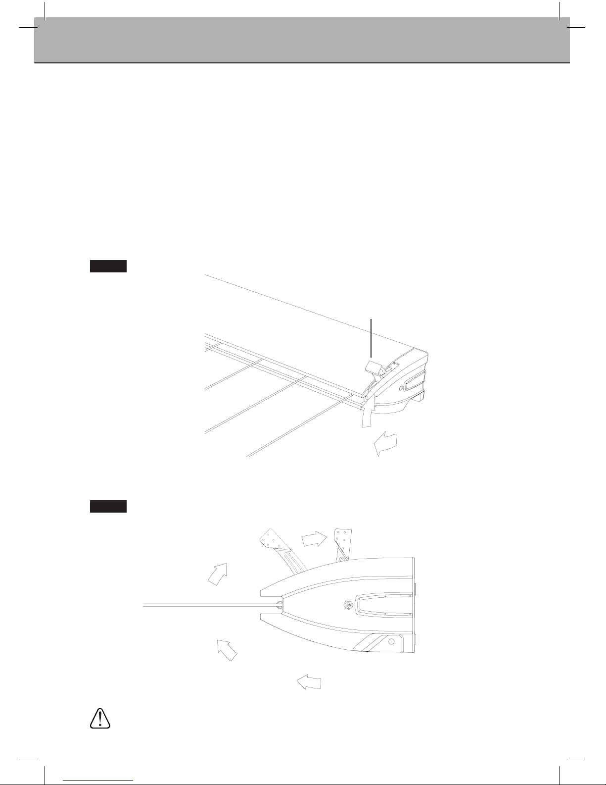
7.2 To attach the arm and line assembly to the receiving bracket
Gripthearmwitheachhandeithersideofthereceivingbracket.
Centrethearmwithinthereceivingbracket.
Rotate and guide the arm downwards to secure it onto the locking pins
inthereceivingbracketuntilaclickingsoundisheard.Thismeansthearm
has engaged (Fig 11).
Fig. 11
Rotate and guide arm downwards
to secure onto locking pins within
thereceivingbracket
15
Operation
Step 7 (continued) – Operation
7.3 To tension and lock the line
Withthearmengagedcorrectlyinthereceivingbracket,rotatethelockinglever(on
the right hand side of the cabinet) (Fig. 12).
Rotate clockwise from the unlocked position until it locates in the first lock position.
Thisprovidesnormaltensiononthelines(Fig. 13).
Check the product is locked by pulling firmly on the lines.
Ifyourequireextratensiononyourlines,rotatethelockingleverfurther,untilit
locates in the second lock position (Fig. 13).
Fig. 12
Fig. 13
1st lock
position
If extra tensioning is
required,movethe
lockinglevertothe
2ndlockposition
2ndlock
position
Lockinglever
WARNING: If your unit is mounted at 4m distance do not use the second lock position.
16
Operation
Step 7 (continued) – Operation
WARNING: Ensure the lines are not under tension before un-latching
and releasing the arm.
7.4 To un-lock and un-tension the lines
Withallclothesandwashingremovedfromthelines;
Pulloutandunlatchthelockingleverfromitslockedposition.
Rotate anti-clockwise to its unlocked position (Fig. 14).
Do notletgoofthelockinglever,asitmayreturnwithsomeforce.
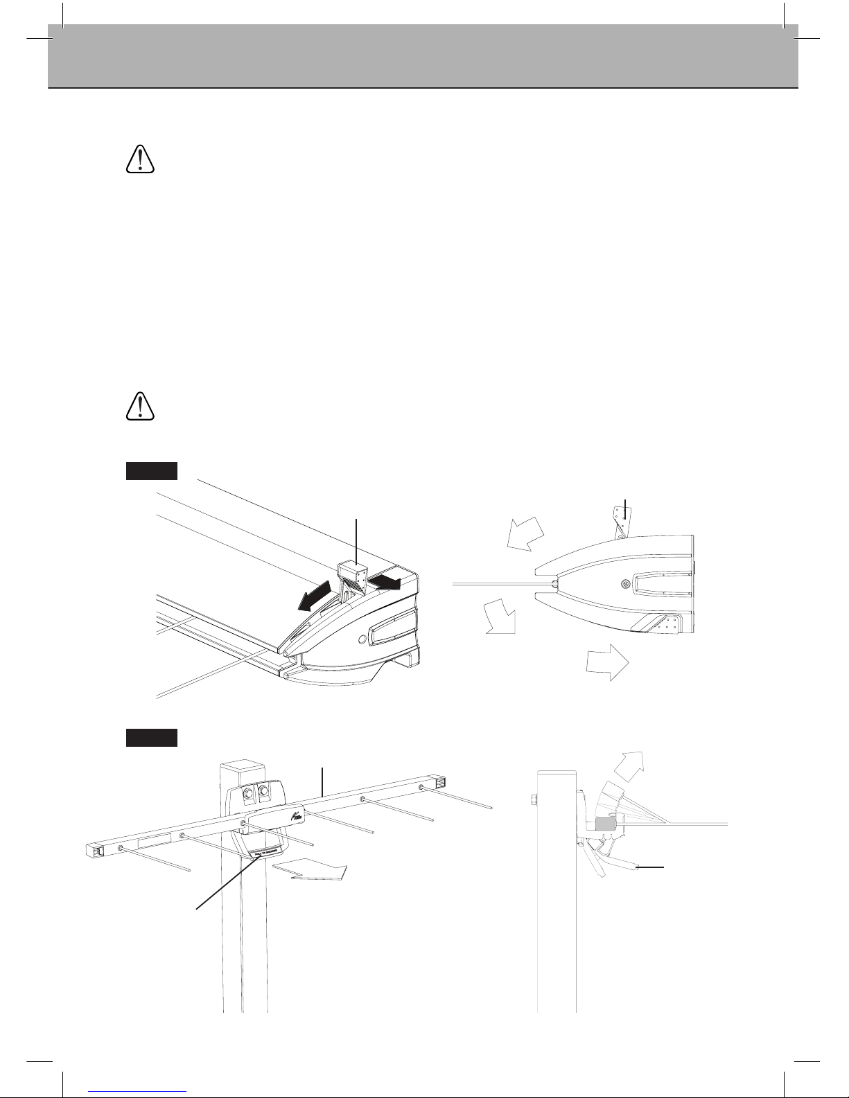
7.5 To remove the arm from the receiving bracket
Using one hand pull the release handle forward as shown. With your other hand,
rotate,guideandliftthearmupandoutofthereceivingbracket(Fig. 15).
WARNING: The lines are under spring tension. Do not allow the arm and lines to
retract uncontrolled as this may lead to personal injury or property product/damage.
Hold the arm securely and walk it back to the cabinet.
Fig. 14
Fig. 15
Lockinglever
Locked
Un-locked
Arm
Release handle
Pullforward
Rotate arm
and lift out of
receivingbracket
Release handle
Pullouttorelease
1
2

17
Hills Handy Hints
Whenhangingthickorbulkyitems,wesuggestyoulaytheitemovermorethanoneline.
Placesmalleritemsofclothingonthelinesatthebackandworkyourwayoutwards
for larger items.
When you don’t expect to fill the capacity of your clothesline, hang your clothes on the
outer lines, as this will allow clothes to dry more easily.
Care and Maintenance
Regularly inspect all components and check for wear and tear or damage.
Ensure fasteners are secure. If there is any damage, parts should be replaced with
original Hills spares. The Clothesline should be repaired before using again.
Your Clothesline should be periodically wiped clean with a damp cloth
and mild detergent.
Wedonotrecommendtheuseofoilor‘WD’typelubricantsonanypart
of the Clothesline.
To maintain appearance and durability of coatings on metal components
we recommend a twice yearly application of a reputable brand of car polish or wax.
Handy Hints

18
Guarantee
Hills Guarantee
Hills Industries Limited undertakes that if any part of its manufacture has failed to operate
correctlyduetofaultyworkmanshipordefectivematerial,itwillrepairorreplacethepart
freeofcostforaperiodofTEN(10)yearsfromdateofpurchaseofthearticle,givenfair
wearandtear.ThePVClineisguaranteedforaperiodofONE(1)year.Evidenceofunfair
usageorincorrectadjustmentbytheownerwillvoidthispromise.
Hills Industries Limited will not be responsible for any costs in connection with freight or
postage, or for expenditure necessary to dismantle the article, replace the part in position
and re assemble the article.
This guarantee is in addition to any legal rights or remedies conferred on the consumer.
Hills Industries Limited does not recommend the application of a ‘canopy’ on any of their
outdoor dryer range.
UnlessanyadditionorattachmenttothisproducthasHillsspecicapprovalorissold
asaHillsproductthewarrantyonthisproductiswaived.Theproductisdesignedto
perform a specific task under established test loads and unauthorised attachments may
produce stresses for which the design is not appropriate.
Designs,specicationsandcoloursaresubjecttochangewithoutnotice.
PleaseretainthisOwner’sManual.Recordthefollowinginformation
from the carton for future reference.
ProductNumber:
Dateofpurchase:
Nameandlocationofstore:
Hills Contacts
AsaproudlyAustraliancompanywearecommittedtoprovideyouwithcomplete
customersatisfaction.Ifyouhavequestionsaboutthisproductorndtherearemissing
ordamagedpartspleasecontactyournearestConsumerAdviceCentreduringtheirlocal
business hours.
Australia
1300300564
New Zealand
092623052
North America
8775341371(Eastern)
South Africa
0214421540
info@stingray.co.za
orvisitwww.hills.com.au
Made in China
Designed and tested under a
Quality System that meets Hills
demanding quality specifications.
®

19
Notes

Hills Industries Limited
A.B.N.35007573417
IssueMarch2010
PD1871j
Other manuals for extenda 4
1
This manual suits for next models
1
Table of contents
Other Hills Personal Care Product manuals


