hilscher NFD-3090-PNS-IOLM/W User manual
User manual
NFD-3090-PNS-IOLM\W
netFIELD IO-Link Wireless Master PROFINET IO-Device
Hilscher Gesellschaft für Systemautomation mbH
www.hilscher.com
DOC201101UM03EN | Revision 3 | English | 2022-02 | Released | Public

Table of contents 2/146
Table of contents
1 Introduction .............................................................................................................................. 5
1.1 About this document ........................................................................................................5
1.2 List of revisions ................................................................................................................5
2 Device description ................................................................................................................... 6
2.1 Functional description ......................................................................................................6
2.2 Device overview ...............................................................................................................7
2.3 Product software ..............................................................................................................9
2.4 Revisions and versions ....................................................................................................9
2.5 Identification ...................................................................................................................10
2.6 Connectors and interfaces .............................................................................................11
2.6.1 Power supply .................................................................................................. 11
2.6.2 Ethernet .......................................................................................................... 11
2.6.3 IO-Link, SMA antenna..................................................................................... 12
2.7 Derating..........................................................................................................................12
3 Safety ...................................................................................................................................... 13
3.1 General note ..................................................................................................................13
3.2 Intended use ..................................................................................................................13
3.3 Personnel qualification ...................................................................................................13
3.4 Power drop during write and delete accesses in the file system....................................14
3.5 Exceeding the maximum number of permitted write and delete accesses ....................14
3.6 Information and data security.........................................................................................14
4 Getting started ....................................................................................................................... 15
5 Requirements ......................................................................................................................... 16
5.1 Hardware and system requirements ..............................................................................16
5.2 Software requirements ...................................................................................................16
6 Mounting and demounting.................................................................................................... 17
6.1 Mounting ........................................................................................................................17
6.1.1 Grounding ....................................................................................................... 19
6.2 Demounting....................................................................................................................19
6.3 Disposal of waste electronic equipment.........................................................................20
7 Connections ........................................................................................................................... 21
7.1 Connection example ......................................................................................................22
8 Configuration ......................................................................................................................... 23
8.1 Configuration tools .........................................................................................................23
8.2 Configuring PROFINET IO.............................................................................................27
8.2.1 Configuring ports / selecting modules............................................................. 28
8.2.2 Setting parameters.......................................................................................... 30
8.3 Configuration with netFIELD Wireless Web Server .......................................................36
8.3.1 Functional overview ........................................................................................ 36
8.3.2 Open netFIELD Wireless Web Server ............................................................ 37
NFD-3090-PNS-IOLM\W | Hardware, installation and commissioning
DOC201101UM03EN | Revision 3 | English | 2022-02 | Released | Public
© Hilscher 2020 - 2022

Table of contents 3/146
8.3.3 Dashboard ...................................................................................................... 38
8.3.4 Licenses.......................................................................................................... 39
8.3.5 Log in or User administration .......................................................................... 39
8.3.6 Device settings................................................................................................ 42
8.3.7 IO-Link Wireless Master settings .................................................................... 53
8.3.8 Device or port information, pairing, IOLWD update ........................................ 61
9 Commissioning ...................................................................................................................... 80
9.1 Setting the IP address....................................................................................................80
9.2 Configuration with netFIELD Wireless Web Server .......................................................82
9.2.1 Configuring the IO-Link Wireless Master ........................................................ 83
9.2.2 Port settings for commissioning ...................................................................... 85
9.3 Testing ...........................................................................................................................89
9.4 Master reset ...................................................................................................................91
9.5 Indexed Service Data Units............................................................................................92
9.6 Wireless .........................................................................................................................94
9.7 Setting date and time .....................................................................................................94
9.8 Using OPC UA Client .....................................................................................................95
9.8.1 Connecting with device ................................................................................... 95
9.8.2 Setting date and time of the device via OPC UA ............................................ 97
10 Communication...................................................................................................................... 99
10.1 Process data of the PROFINET IO-Device ....................................................................99
10.1.1 Process data of submodule „IO-Link Wireless Master“................................... 99
10.1.2 Process data of submodules „IO-Link Wireless Device X I / X O + PQI“...... 100
10.1.3 Process data of submodules „IO-Link Wireless Device X I + PQI“ ............... 101
10.1.4 Process data of submodules „IO-Link Wireless Device X O + PQI“ ............. 102
10.1.5 Port Qualifier Information .............................................................................. 103
10.1.6 Provider and consumer status ...................................................................... 103
10.2 OPC UA .......................................................................................................................104
10.2.1 Device identification ...................................................................................... 105
10.2.2 Identification of connected IO-Link Devices.................................................. 105
10.2.3 NTP Client configuration ............................................................................... 106
10.3 MQTT topics.................................................................................................................107
10.3.1 General parts of a topic................................................................................. 107
10.3.2 Gateway topics ............................................................................................. 107
10.3.3 Master topics................................................................................................. 109
10.3.4 Device topics................................................................................................. 113
10.3.5 MQTT topics ................................................................................................. 116
11 Diagnosis.............................................................................................................................. 117
11.1 Diagnosis via LEDs ......................................................................................................117
11.1.1 System LED .................................................................................................. 117
11.1.2 APL LED ....................................................................................................... 118
11.1.3 Supply voltage status.................................................................................... 118
11.1.4 PROFINET IO-Device status ........................................................................ 119
11.1.5 Wireless track status..................................................................................... 120
11.1.6 Wireless port status ...................................................................................... 120
11.2 Diagnosis over IO-Link.................................................................................................121
11.2.1 Event Qualifier .............................................................................................. 121
11.2.2 IO-Link Wireless Master Event Codes .......................................................... 121
11.2.3 IO-Link Device Event Codes (common)........................................................ 122
NFD-3090-PNS-IOLM\W | Hardware, installation and commissioning
DOC201101UM03EN | Revision 3 | English | 2022-02 | Released | Public
© Hilscher 2020 - 2022

Table of contents 4/146
12 Technical data ...................................................................................................................... 124
12.1 Technical data device ..................................................................................................124
12.2 Technical data IO-Link Wireless Master ......................................................................126
12.3 Technical data protocol ................................................................................................126
12.4 Technical data netFIELD Wireless Web Server...........................................................127
12.5 OPC UA Server............................................................................................................127
12.6 MQTT Client.................................................................................................................127
13 Dimensions........................................................................................................................... 128
13.1 Dimensions netFIELD IO-Link Wireless Master device ...............................................128
14 Approvals ............................................................................................................................. 129
14.1 FCC/ISED ....................................................................................................................129
15 Appendix............................................................................................................................... 131
15.1 References...................................................................................................................131
15.2 Conventions in this manual ..........................................................................................132
15.3 Directives and standards..............................................................................................133
15.4 Legal notes...................................................................................................................134
15.5 Registered trademarks.................................................................................................138
Glossary................................................................................................................................ 144
Contacts................................................................................................................................ 146
NFD-3090-PNS-IOLM\W | Hardware, installation and commissioning
DOC201101UM03EN | Revision 3 | English | 2022-02 | Released | Public
© Hilscher 2020 - 2022
Introduction 5/146
1 Introduction
1.1 About this document
This document describes the netFIELD IO-Link Wireless Master PROFINET
IO-Device NFD-3090-PNS-IOLM\W device.
1.2 List of revisions
Index Date Revision
1 2020-11-12 Document created.
2 2021-08-31 Description: Section Device description [}page6] updated, sections Product
software [}page9] and Derating [}page12] added.
Configuration: Section Configuration tools [}page23] updated. Section Configuring
PROFINET IO [}page27] updated, section Setting parameters [}page30] updated.
Section Configuration with netFIELD Wireless Web Server [}page36] description updated
(subsections Device ISDU [}page74] and Port settings for commissioning [}page85],
and further updates).
Commissioning: Sections Setting date and time [}page94], and Using OPC UA
Client [}page95] added.
Communication: Section Process data of the PROFINET IO-Device [}page99] revised.
Section NTP Client configuration [}page106] added, and sections MQTT
topics [}page107] with General parts of a topic [}page107] added.
Diagnosis: Section PROFINET IO-Device status [}page119] updated; section Wireless port
status [}page120] updated.
Technical data: Section Technical data device [}page124] updated. Sections Technical
data IO-Link Wireless Master [}page126], Technical data netFIELD Wireless Web
Server [}page127], OPC UA Server [}page127] and MQTT Client [}page127] added.
Section Technical data protocol [}page126] updated.
Approvals: Chapter Approvals [}page129] added. Appendix: Section Directives and
standards [}page133] added.
3 2022-02-25 Product released.
Description: Section Revisions and versions [}page9] and section
Identification [}page10] updated.
Connections: Section Connection example [}page22] updated.
Configuration: Section Configuration with netFIELD Wireless Web Server [}page36]
description updated (subsections Pairing [}page70] and IOLWD Update [}page72]
added, and further updates).
Communication: Section OPC UA [}page104] updated, section Device topics [}page113]
updated, section MQTT topics [}page107] corrected.
Diagnosis: Section APL LED [}page118] updated.
Table1: List of revisions
NFD-3090-PNS-IOLM\W | Hardware, installation and commissioning
DOC201101UM03EN | Revision 3 | English | 2022-02 | Released | Public
© Hilscher 2020 - 2022

Device description 6/146
2 Device description
2.1 Functional description
The IO-Link Wireless Master NFD-3090-PNS-IOLM\W device is intended
for use within a PROFINET network.
The device enables the operation of up to 16 IO-Link Devices via a wireless
connection. An IO-Link Device could be an IO-Link sensor/actuator.
Parameterization, configuration
·The device is parameterized via PROFINET IO. The device stores the
parameters.
·Alternatively, the IO-Link Wireless Master and the wireless IO-Link ports
of the device can be configured using the integrated netFIELD Wireless
Web Server. The netFIELD Wireless Web Server enables you to
parameterize the IO-Link Devices connected via a wireless connection
to the IO-Link Wireless Master device.
·Or, you can use the IO-Link engineering tool “IO-Link E.T.” to configure
the IO-Link Wireless Master and the wireless IO-Link ports of the
device, as well as IO-Link Devices parameters based on IODD file.
·OPC UA Server is also integrated and offers identification, and status.
·The device provides MQTT topics for device identification, device
capabilities, configuration status, address data, process data, event logs
or device parameters.
For further information see section Configuration tools [}page23].
NFD-3090-PNS-IOLM\W | Hardware, installation and commissioning
DOC201101UM03EN | Revision 3 | English | 2022-02 | Released | Public
© Hilscher 2020 - 2022
Device description 7/146
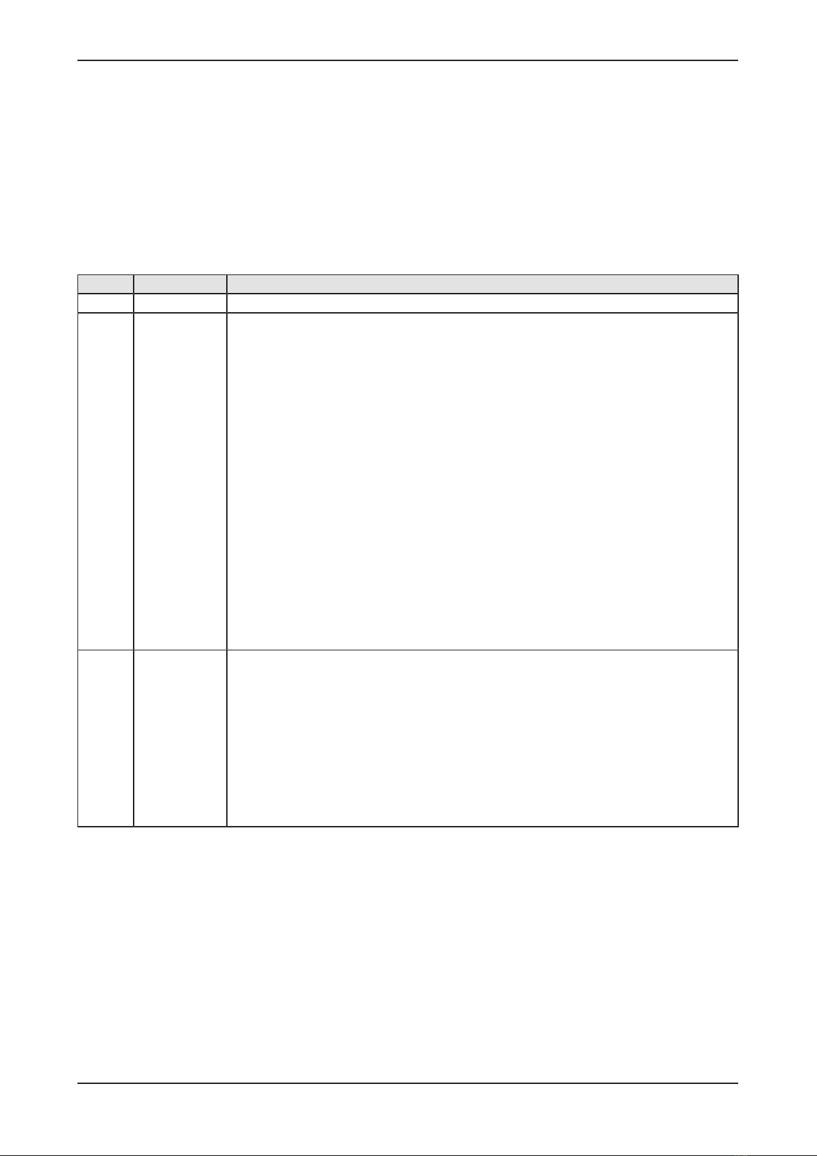
2.2 Device overview
Figure1: Device overview, NFD-3090-PNS-IOLM\W
Manufacturer, product identification, and technical data can be found on the
device housing as laser engravings.
NFD-3090-PNS-IOLM\W | Hardware, installation and commissioning
DOC201101UM03EN | Revision 3 | English | 2022-02 | Released | Public
© Hilscher 2020 - 2022

Device description 8/146
Function Pos. Name Description For details, see section
Ethernet (32) X31 Ethernet interface, M12, D-coded,
PROFINET IO port 1 (CH0)
Ethernet [}page11]
(10) X32 Ethernet interface, M12, D-coded,
PROFINET IO port 2 (CH1)
(30) LINK (X31) Link LED for connector X31 PROFINET IO-Device
status [}page119]
(31) ACT (X31) Activity LED for connector X31
(28) ACT (X32) Activity LED for connector X32
(29) LINK (X32) Link LED for connector X32
(9) - Labeling fields Ethernet interfaces X31 and X32 -
LEDs (34) SYS System status LED System LED [}page117]
(33) APL Application status LED APL LED [}page118]
(7) SF System Failure LED PROFINET IO-Device
status [}page119]
(8) BF Bus Failure LED
Power supply (25) X21 Power supply input (PWR IN), M12, L-coded Power supply [}page11]
(13) X22 Power supply output (PWR OUT), M12, L-coded
(12) 1L (X21) 1L supply voltage status LED (DC 24 V) Supply voltage
status [}page118]
(14) 2L (X21) 2L supply voltage status LED (DC 24 V)
(11) - Labeling fields power supply input X21
and output X22
-
Antenna
connectors and
LEDs for IO-
Link wireless
radio module
(23) X1 Connector for SMA antenna for IO-Link wireless
connection to the IO-Link Devices 1 to 8
IO-Link, SMA
antenna [}page12]
(16) X2 Connector for SMA antenna for IO-Link wireless
connection to the IO-Link Devices 9 to 16
(21) X3 Connector for SMA antenna
(22),
(20)
- Labeling fields SMA antennas X1, X2, and X3 -
(24) WT1 …
WT3
IO-Link wireless track status LEDs Wireless track
status [}page120]
(15) WP01 …
WP08
Port status LEDs for
wireless IO-Link ports WP01 … WP08
Wireless port
status [}page120]
(17) WP09 …
WP16
Port status LEDs for
wireless IO-Link ports WP09 … WP16
Device
identification
(26) - QR code Identification [}page10]
(27) - Product group and model
(35) Logo communication field bus
(36) - Part number, model, serial number, MAC address
(19) - Device labeling field -
Manufacturer (37) Manufacturer address Contacts [}page146]
Technical data (1), (5) - Space for certification signs and IDs Technical data
(4) - Power supply (SELV / PELV), fuse protection,
temperature range, protection class
Safety and
disposal
(2), (3) - Signs on safety and environment (disposal) Mounting and
demounting [}page17]
Mounting (6) - Mounting hole and grounding
(18) - Mounting hole
Table2: Legend to the device overview, NFD-3090-PNS-IOLM\W
NFD-3090-PNS-IOLM\W | Hardware, installation and commissioning
DOC201101UM03EN | Revision 3 | English | 2022-02 | Released | Public
© Hilscher 2020 - 2022
Device description 9/146
2.3 Product software
All the information and software you need for your product can be
downloaded free of charge at the web-link
https://kb.hilscher.com/display/NFDIOLWM
ØSelect the link for the current release for the product software.
After the download, you can start commissioning and configuring your
device immediately.
ØCheck our website regularly for software updates for your product.
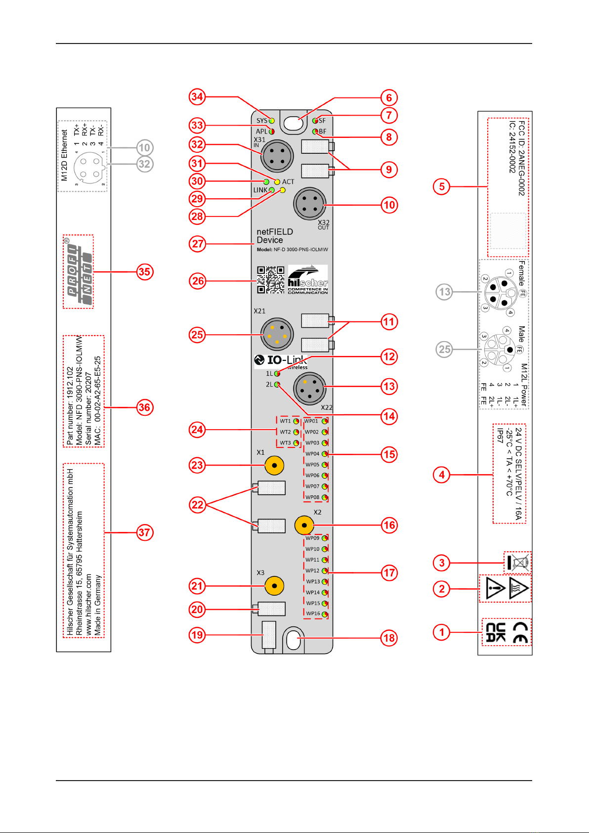
2.4 Revisions and versions
The hardware revision listed below, as well as the software and firmware
versions belong together functionally. If a hardware installation is available,
for the firmware update these specifications are relevant.
Model Description Part
number
Hardware
revision
NFD-3090-PNS-IOLM\W netFIELD IO-Link Wireless Master
PROFINET IO-Device
1912.102 3
Table3: Hardware
Software Version
netFIELD Wireless Web Server 1.1
IO-Link ET 1.0
Table4: Software
Protocol File name Note Version
PROFINET IO-Device U197D001.nxi,
U197D001.nxe,
U197D001.nai
nxi for COM CPU,
with nxe for extension.
nai for APP CPU.
2.2
Table5: Firmware
Description Version
IO-Link Wireless Master stack 8.3
Radio module revision 2.3
Table6: IO-Link Wireless Master
NFD-3090-PNS-IOLM\W | Hardware, installation and commissioning
DOC201101UM03EN | Revision 3 | English | 2022-02 | Released | Public
© Hilscher 2020 - 2022

Device description 10/146
2.5 Identification
On the front side of the NFD-3090-PNS-IOLM\W device housing a QR code
is provided for device identification.
Figure2: QR code (example)
The QR code includes product identification data in two lines:
1st line (with example data):
·Part number: 1912.102
·Character “R” and hardware revision number: R4
·Serial number: 020000
·MAC ID: 00-02-A2-02-20-E3
2nd line: URL link to product homepage
Example:
1912.102 R4 20000 00-02-A2-02-20-E3
https://www.hilscher.com/netfield/netfield-device/
To find the QR code in the device overview, see position (26) in section
Device overview [}page7].
NFD-3090-PNS-IOLM\W | Hardware, installation and commissioning
DOC201101UM03EN | Revision 3 | English | 2022-02 | Released | Public
© Hilscher 2020 - 2022

Device description 11/146
2.6 Connectors and interfaces
2.6.1 Power supply
Connectors X21 and X22
The device is supplied via connector X21 (PWR IN). You can connect two
supply lines to the connector:
·Supply line 1: 1L+ (U1L) and the reference potential 1L-
·Supply line 2: 2L+ (U2L) and the reference potential 2L-
Both supply lines are electrically isolated.
Each pin of connector X21 (PWR IN) is connected to the same pin of
socket X22 (PWR OUT) and is used to forward the supply to the next
device.
For identifying the connector X21 of the NFD-3090-PNS-IOLM\W device,
see position (25), and connector X22, see position (13) in section Device
overview [}page7].
Supply voltage input Supply voltage output Pin Signal Description
1
2
3
4
FE
M12, L-coded,
plug,
5-pin (4 + FE)
1
2
3
4
FE
M12, L-coded,
socket,
5-pin (4 + FE)
1 1L+ 24 V DC supply voltage U1L for system and sensor/
actuator
2 2L- Reference potential for 2L
3 1L- Reference potential for 1L
4 2L+ 24 V DC auxiliary/control voltage U2L
FE FE Functional earth
Table7: Supply voltage
2.6.2 Ethernet
·Connector X31 for Ethernet interface port 1 (CH0)
·Connector X32 for Ethernet interface port 2 (CH1)
For identifying the connector X31 of the NFD-3090-PNS-IOLM\W device,
see position (32), and connector X32, see position (10) in section Device
overview [}page7].
Connectors X31 and X32
Ethernet Pin Signal Description
12
3
4
1
2
3
4
M12, D-coded, socket, 4-pin
1 TX+ Transmit data positive
2 RX+ Receive data positive
3 TX– Transmit data negative
4 RX– Receive data negative
Table8: Ethernet
NFD-3090-PNS-IOLM\W | Hardware, installation and commissioning
DOC201101UM03EN | Revision 3 | English | 2022-02 | Released | Public
© Hilscher 2020 - 2022
Device description 12/146
2.6.3 IO-Link, SMA antenna
With the NFD-3090-PNS-IOLM\W device, two tracks with each up to 8 and
together up to 16 IO-Link Devices simultaneously can be supported.
IO-Link Devices
The type of data transferred (length and data type, etc.) depends on the
connected IO-Link Devices.
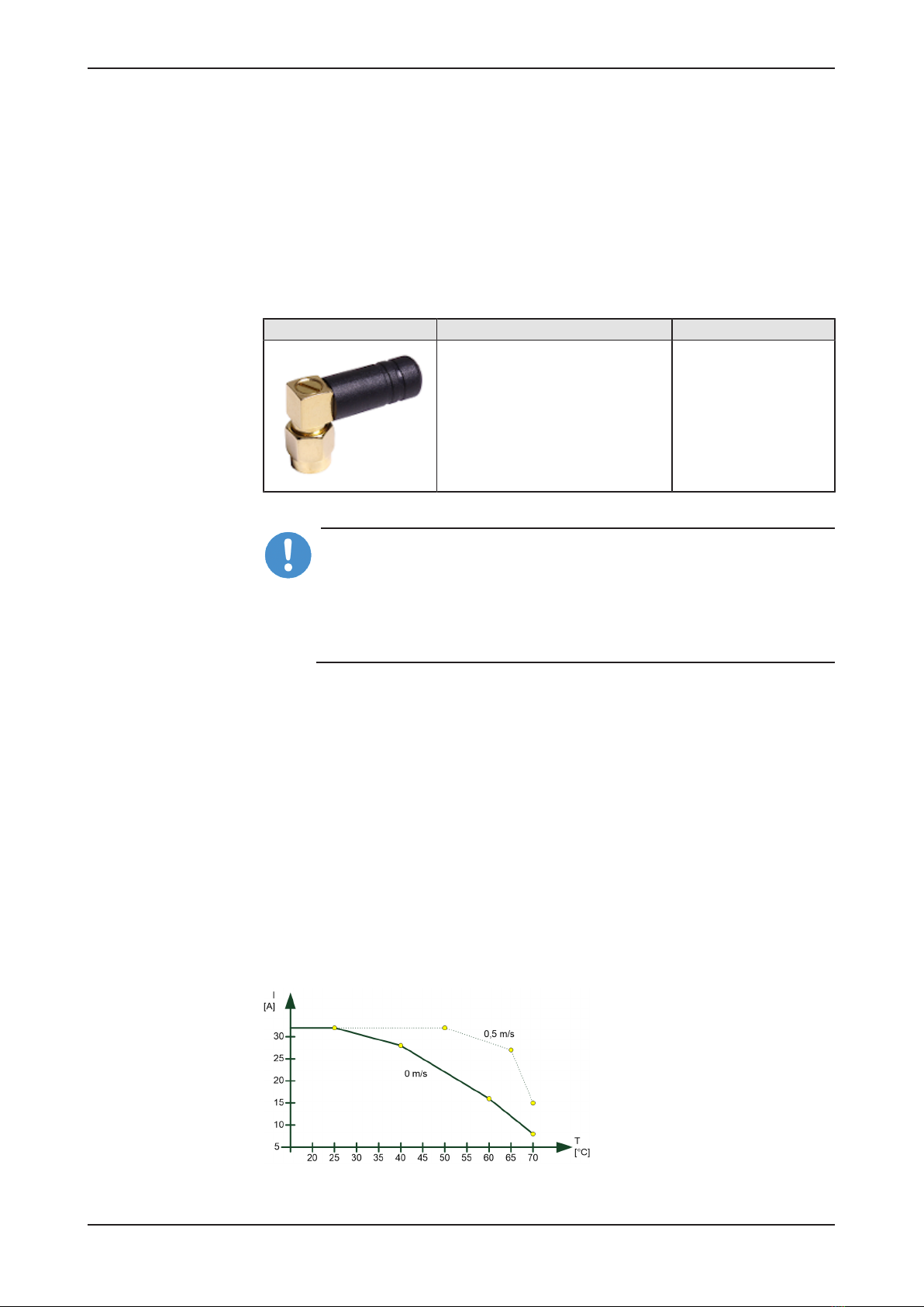
SMA antenna
Antenna SMA Type Manufacturer
Wifi Antenna 2.4G rubber antenna,
Model: TLW2.5A-SMA-Male
Bandwidth: 1000 MHz
Impedance: 50 Ohms
Silram Technologies
Ltd., Kfar Saba, Israel
Table9: SMA antenna type
Important:
The use of an SMA antenna other than the SMA antenna supplied
with the product is not permitted. This could result in losing the
approval for your device.
For proper device operation, all three SMA antennas X1, X2, and
X3 must be mounted.
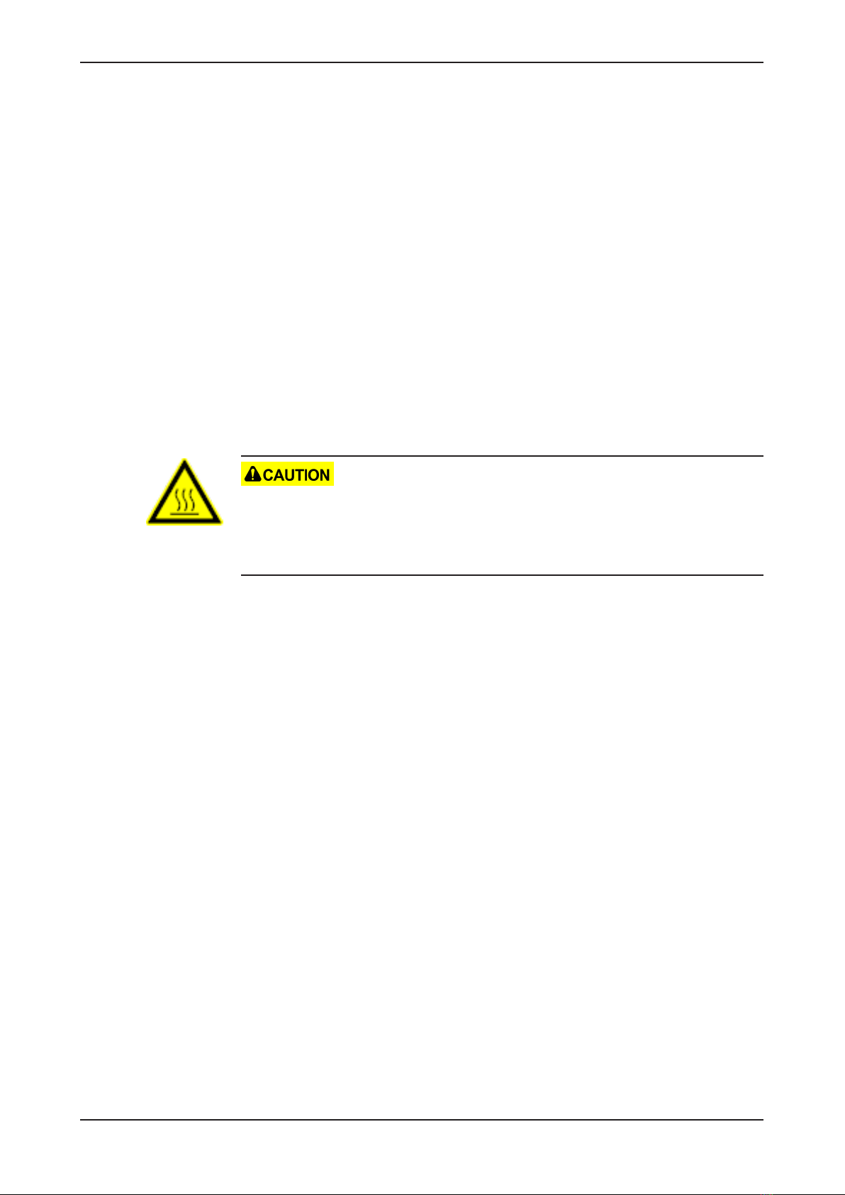
2.7 Derating
Note the derating when using the netFIELD IO-Link Wireless Master
device, when you connect a device to Power Out at the device and thus a
larger current is passed through the device. The ambient temperature and
the current have influence on the heating of the device.
The derating curve was created with the operating conditions "without air
flow or with air flow 0.5 m/s" as well as "mounting on poorly heat
conducting wall". The real operating conditions can lead to a better heat
dissipation of the device for example by a higher air flow or a better heat
dissipation to the mounting wall.
The following figure shows the maximum permissible current (I) that may
flow into the device as a function of the ambient temperature (T).
Figure3: Derating netFIELD IO-Link Wireless Master device
NFD-3090-PNS-IOLM\W | Hardware, installation and commissioning
DOC201101UM03EN | Revision 3 | English | 2022-02 | Released | Public
© Hilscher 2020 - 2022

Safety 13/146
3 Safety
3.1 General note
The documentation in the form of a user manual, an operating instruction
manual or other manual types, as well as the accompanying texts have
been created for the use of the products by qualified personnel. When
using the products, all Safety Messages, Integrated Safety Messages,
Property Damage Messages and all valid legal regulations must be obeyed.
Technical knowledge is presumed. The user has to assure that all legal
regulations are obeyed.
3.2 Intended use
The device netFIELD IO-Link Wireless Master PROFINET IO-Device
NFD-3090-PNS-IOLM\W is used to receive or send process data via IO-
Link:
·The IO-Link Wireless Master device receives process data from the
connected IO-Link Device (sensor) and sends this data to a higher-level
control system.
·The IO-Link Wireless Master device sends process data received from
the higher-level control system to the connected IO-Link Device
(actuator).
3.3 Personnel qualification
The device may only be mounted, configured, operated or demounted by
qualified personnel. Job-specific technical skills for people professionally
working with electricity must be present concerning the following topics:
·Safety and health at work
·Mounting and connecting of electrical equipment
·Measurement and analysis of electrical functions and systems
·Evaluation of the safety of electrical systems and equipment
·Installing and configuring IT systems
NFD-3090-PNS-IOLM\W | Hardware, installation and commissioning
DOC201101UM03EN | Revision 3 | English | 2022-02 | Released | Public
© Hilscher 2020 - 2022

Safety 14/146
3.4 Power drop during write and delete accesses in the file
system
The FAT file system in the netX firmware is subject to certain limitations in
its operation. Write and delete accesses in the file system (firmware
update, configuration download etc.) can destroy the FAT (File Allocation
Table) if the accesses cannot be completed if the power drops. Without a
proper FAT, a firmware may not be found and cannot be started.
ØMake sure that the power supply of the device does not drop during
write and delete accesses in the file system (firmware update,
configuration download etc.).
3.5 Exceeding the maximum number of permitted write and
delete accesses
This device uses a serial flash chip to store remanent data such as
firmware storage, configuration storage, etc. This device allows a maximum
of 100,000 write/delete accesses that are sufficient for standard operation
of the device. However, writing/deleting the chip excessively (e.g. changing
the configuration or changing the name of station) leads to the maximum
number of permitted write/delete accesses being exceeded and to device
damage. For example, if the configuration is changed once an hour, the
maximum number is reached after 11.5 years. If the configuration is
changed even more frequently, for example once a minute, the maximum
number is reached after approx. 69 days.
Avoid exceeding the maximum permitted write/delete accesses by writing
too often.
3.6 Information and data security
Take all usual measures for information and data security, in particular, for
devices with Ethernet technology. Hilscher explicitly points out that a device
with access to a public network (Internet) must be installed behind a firewall
or only be accessible via a secure connection such as an encrypted VPN
connection. Otherwise, the integrity of the device, its data, the application
or system section is not safeguarded.
Hilscher cannot assume any warranty or liability for damage due to
neglected security measures or incorrect installation.
NFD-3090-PNS-IOLM\W | Hardware, installation and commissioning
DOC201101UM03EN | Revision 3 | English | 2022-02 | Released | Public
© Hilscher 2020 - 2022

Getting started 15/146
4 Getting started
Below you will find an overview of the steps required for installation and
commissioning of your IO-Link Wireless Master device:
Step Description Refer to section
Requirements
and preparation
·Prepare the device installation and commissioning according to the
requirements on hardware, system, and software.
·Prepare the required mounting tools.
Requirements [}page16]
Mounting [}page17]
Safety ·Read the mounting instructions and the safety instructions on
connecting and commissioning the device.
·Disconnect the system to which the device will be mounted from the
power supply.
Mounting [}page17]
Mounting ·Mark the positions to fasten the device with screws and cut the M4
holes.
·Fasten the device with the screws.
·Ground the device.
·Mount all three SMA antennas.
Mounting [}page17]
Grounding [}page19]
Connecting and
booting
·Connect the Ethernet M12 cable to the NFD-3090-PNS-IOLM\W device
and to the PLC (PROFINET IO-Controller).
·Connect the +24 V DC SELV or PELV power supply to the NFD-3090-
PNS-IOLM\W device.
·Connect the +24 V DC SELV or PELV power supply to the IO-Link
Device.
·Switch on the power supply units of the device and of the IO-Link
Device.
Connections [}page21]
Commissioning In the configuration software of the PROFINET IO-Controller:
·Configure the PROFINET IO-Controller: Import the GSDML file
- GSDML-V2.35-HILSCHER-NETFIELD-WIRELESS-PDCT-
YYYYMMDD.xml (if you use the netFIELD Web Server to perform the
settings of the IO-Link Wireless Master parameters or the wireless IO-
Link port parameters),
- or GSDML-V2.35-HILSCHER-NETFIELD-WIRELESS-EXPERT-
YYYYMMDD.xml (if you use the configuration software of the
PROFINET IO-Controller for this purpose).
·Create the configuration project with the PROFINET IO-Controller and
PROFINET IO-Device, select the modules and submodules and set the
parameters.
For the subsequent steps the following configuration tools can be used:
·Configure the IO-Link Wireless Master NFD-3090-PNS-IOLM\W using
the netFIELD Wireless Web Server.
·Configure the wireless IO-Link port parameters via the configuration
software of the PROFINET IO-Controller or using the netFIELD
Wireless Web Server.
·Configure the IO-Link Device.
Configuration
tools [}page23]
Configuring PROFINET
IO [}page27]
Commissioning [}page80]
Table10: Overview for installation and commissioning
NFD-3090-PNS-IOLM\W | Hardware, installation and commissioning
DOC201101UM03EN | Revision 3 | English | 2022-02 | Released | Public
© Hilscher 2020 - 2022

Requirements 16/146
5 Requirements
5.1 Hardware and system requirements
To install your IO-Link Wireless Master you need the following hardware
elements:
·Power supply: 24 V DC SELV (Safety Extra Low Voltage) or PELV
(Protective Extra Low Voltage) power supply
·Power supply cable with L-coded M12 connector
·Ethernet cable with D-coded M12 connector
·PROFINET IO-Controller (PLC)
·At least one
IO-Link Wireless Device or
a Wireless Bridge and a wired IO-Link Device
·3 x SMA antenna: Use type Wifi Antenna 2.4G rubber antenna, model
“TLW25A-SMA-Male” only (see section IO-Link, SMA
antenna [}page12]).
Additional components
·Ethernet network switch
For commissioning
·PC or notebook with at least one additional Ethernet port and Internet
access
5.2 Software requirements
For commissioning and configuring your IO-Link Wireless Master, the
following requirements must comply:
·Web browser if integrated netFIELD Wireless Web Server is to be used
for configuration.
For further information see section Configuration tools [}page23].
NFD-3090-PNS-IOLM\W | Hardware, installation and commissioning
DOC201101UM03EN | Revision 3 | English | 2022-02 | Released | Public
© Hilscher 2020 - 2022

Mounting and demounting 17/146
6 Mounting and demounting
6.1 Mounting
Required tools for mounting the device
You will need the following tools for mounting:
·Allen key for the M4 mounting screws with hexagon socket
Only additionally required for mounting without existing mounting holes:
·M4 thread tap (ready-made or set of taps)
·Drilling machine (to pre-drill the mounting holes as M4 threads for
mounting the device to the system)
You will also need two M4 hexagon cylinder head screws according to DIN
912 / ISO 4762 of suitable length.
Before mounting the device
Always observe the following instructions:
·The device may only be mounted and commissioned by qualified
electricians in accordance with EN 50110-1/-2 and IEC 60364.
·Refer to the safety instructions in the Safety [}page13] chapter.
·Before mounting the device, check for damage, e.g. transport damage!
Damaged devices must not be put into operation.
Mounting instructions
Observe the following points when selecting the mounting location:
·When mounting outside buildings: Mount the device in such a way that
it is protected from weathering, especially from direct sunlight and the
effects of UV light, salt water or salt spray, e.g. in a switch box.
·Only screw the device on flat contact surfaces to protect it from
mechanical tension.
·Do not bridge any gaps with the device to protect it from any tensile
forces that may occur.
·To prevent damage to the device, do not mount it in shearing areas of
moving system parts. Also, lay the cables in such a way that they
cannot be caught in the shear zones of moving system parts.
·Leave sufficient space for easy replacement of the device and for
connecting the plug connections.
·Ensure that the requirements of the device for vibration and shock
resistance are met at the mounting site.
·Mount the device so that the diagnostic LEDs of the device remain
visible.
NFD-3090-PNS-IOLM\W | Hardware, installation and commissioning
DOC201101UM03EN | Revision 3 | English | 2022-02 | Released | Public
© Hilscher 2020 - 2022

Mounting and demounting 18/146
Observe the following instructions for the mounting procedure:
·Disconnect the system from the power supply before you start
mounting.
·Ensure sufficient equipotential bonding in your system.
·During mounting, make sure that you do not soil the connections. Dirt
will damage the contacts, resulting in reduced contact reliability.
Notes on protection against the heat generated by the device
The device can get hot during operation! Therefore, always observe the
following instructions:
·The cooling of the device must not be impaired.
·Ensure an unobstructed air supply!
·Do not install the device near strong heat sources!
·Do not mount the device on or near highly inflammable materials.
Mounting of the device
You can attach the device directly to your system or in the control cabinet
with screws. Fasten the device to a flat, solid base with two M4 screws,
each of which is screwed into a mounting hole. Section Technical
data [}page124] contains the specification of the tightening torque.
Note:
Note that the device requires a connection to FE (functional earth)
plate at the plastic housing via the screws.
The procedure for this is as follows:
ØHold the device in the desired position and mark the two points where
the M4 threads are to be cut. Make sure that there is enough space
around the device so that you can connect all cables without any
problems.
ØCut an M4 thread at each of the two marked points with the M4 thread
cutter, if necessary pre-drill with the drill first.
ØScrew the device into the mounting holes with the Allen key using two
M4 cylinder head screws of suitable length at the upper and lower ends.
Observe the tightening torque.
After mounting
Observe the notes on Grounding [}page19].
Mounting of the SMA antennas
Important:
For proper device operation, all three SMA antennas X1, X2, and
X3 must be mounted.
NFD-3090-PNS-IOLM\W | Hardware, installation and commissioning
DOC201101UM03EN | Revision 3 | English | 2022-02 | Released | Public
© Hilscher 2020 - 2022
Mounting and demounting 19/146
6.1.1 Grounding
Functional earth
The L-coded M12 connectors of the power supply of the NFD-3090-PNS-
IOLM\W device have a pin FE (functional earth). You can ground the
device via FE of the power supply connection or via the screws to the FE
plate at the plastic housing. Grounding the device is recommended.
6.2 Demounting
Required tools for demounting
For demounting, you need an Allen key to loosen the M4 hexagon socket
head screws according to DIN 912 or ISO 4762.
Before demounting
Prepare for demounting:
Device is hot!
During operation, high surface temperatures can occur on the housing and
at the metal connections, especially at the M12 connector sleeve. If the
device was in operation, let it cool down before touching it or use gloves.
ØDisconnect the part of the plant to which you have mounted the device
from the power supply.
ØIf the device is dirty, clean it first. It is particularly important to clean dirty
screw connections.
ØBefore demounting, loosen all screw connections at the terminals and
disconnect the cables.
Demounting
To disassemble the device, e.g. when replacing the device, proceed as
follows:
ØMake sure that the part of the plant on which you have mounted the
device is zero-potential.
ØUse the Allen key to loosen the two M4 cylinder head screws.
ØRemove the device.
After demounting
If the demounted device is defective, mark it as defective to prevent the
device from being used again.
NFD-3090-PNS-IOLM\W | Hardware, installation and commissioning
DOC201101UM03EN | Revision 3 | English | 2022-02 | Released | Public
© Hilscher 2020 - 2022

Mounting and demounting 20/146
6.3 Disposal of waste electronic equipment
Important notes from the European Directive 2012/19/EU “Waste Electrical
and Electronic Equipment (WEEE)”
Waste electronic equipment
This product must not be treated as household waste.
This product must be disposed of at a designated waste electronic
equipment collecting point.
Waste electronic equipment may not be disposed of as household waste.
As a consumer, you are legally obliged to dispose of all waste electronic
equipment according to national and local regulations.
NFD-3090-PNS-IOLM\W | Hardware, installation and commissioning
DOC201101UM03EN | Revision 3 | English | 2022-02 | Released | Public
© Hilscher 2020 - 2022
This manual suits for next models
1
Table of contents
Other hilscher Network Hardware manuals


Popular Network Hardware manuals by other brands


NETGEAR
NETGEAR M5300 Series Software administration manual

Optocore
Optocore AutoRouter quick start guide

Cisco
Cisco OL-7822-06 quick start guide

evertz
evertz 7720AE Series manual

TRENDnet
TRENDnet TEW-435BRM - 54MBPS 802.11G Adsl Firewall M Quick installation guide

Digital Equipment
Digital Equipment DLE28-MA user guide