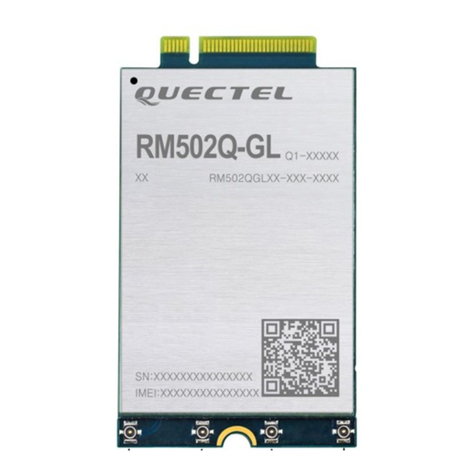
5G Module Series
RM500Q-AE&RM502Q-AE Hardware Design
RM500Q-AE&RM502Q-AE_Hardware_Design 7 / 83
Table Index
Table 1: Frequency Bands and GNSS Type of RM500Q-AE&RM502Q-AE Module............................1412
Table 2: Key Features of RM500Q-AE&RM502Q-AE...........................................................................1513
Table 3: Definition of I/O Parameters.....................................................................................................2219
Table 4: Pin Description.........................................................................................................................2219
Table 5: Overview of Operating Modes.................................................................................................2623
Table 6: Definition of VCC and GND Pins.............................................................................................2624
Table 7: Definition of FULL_CARD_POWER_OFF# Pin.......................................................................2926
Table 8: Definition of RESET_N Pin......................................................................................................3229
Table 9: Pin Definition of (U)SIM Interfaces ..........................................................................................3431
Table 10: Pin Definition of USB Interface..............................................................................................3734
Table 11: Pin Definition of PCIe Interface..............................................................................................3936
Table 12: Pin Definition of PCM Interface..............................................................................................4441
Table 13: Pin Definition of Control and Indication Interfaces.................................................................4542
Table 14: RF Function Status ................................................................................................................4643
Table 15: GNSS Function Status...........................................................................................................4643
Table 16: Network Status Indications of WWAN_LED#........................................................................4845
Table 17: State of the WAKE_ON_WAN#.............................................................................................4845
Table 18: Function of the DPR Signal....................................................................................................4946
Table 19: Pin Definition of COEX Interface ...........................................................................................4946
Table 20: Pin Definition of Antenna Tuner Control Interface.................................................................5047
Table 21: Definition of Configuration Pins..............................................................................................5047
Table 22: Configuration Pins List of M.2 Specification..........................................................................5148
Table 23: GNSS Performance ...............................................................................................................5249
Table 24: RM500Q-AE&RM502Q-AE Pin Definition of RF Antenna Interfaces....................................5451
Table 25: RM500Q-AE & RM502Q-AE RF Antenna Mapping..............................................................5552
Table 26: RM500Q-AE&RM502Q-AE Module Operating Frequencies.................................................5552
Table 27: GNSS Frequency...................................................................................................................5755
Table 28: RF Bands Supported by RM500Q-AE&RM502Q-AE Antenna Connectors..........................6159
Table 29: Antenna Requirements..........................................................................................................6260
Table 30: Major Specifications of the RF Connector.............................................................................6361
Table 31: Absolute Maximum Ratings...................................................................................................6664
Table 32: Power Supply Requirements .................................................................................................6664
Table 33: I/O Requirements...................................................................................................................6765
Table 34: Operating and Storage Temperatures...................................................................................6765
Table 35: RM500Q-AE&RM502Q-AE Current Consumption................................................................6866
Table 36: RF Output Power ...................................................................................................................7171
Table 37: RM500Q-AE&RM502Q-AE Conducted RF Receiving Sensitivity.........................................7171
Table 38: Electrostatic Discharge Characteristics (Temperature: 25 ºC , Humidity: 40 %)...................7374
Table 39: Related Documents................................................................................................................8081
Table 40: Terms and Abbreviations.......................................................................................................8081
错误!超链接引用无效。Table 1: Frequency Bands and GNSS Type of
