Hioki 3286-20 User manual

3286B981-13
Contents
Introduction i
Shipping Check ii
Safety iii
Note on Use vii
Organization of This Manual xiii
Chapter 1 Product Outline 1
1.1 Product Outline 1
1.2 Features 2
1.3 Parts and Functions 3
1.4 Flowchart of Key Operations 9
1.4.1 Current Measurements Mode 9
1.4.2 Harmonic Measurement 11
1.4.3 Change the Range 11
Chapter 2 Measurement Procedure 13
2.1 Preparations 13
2.2 Connections 14
2.3 Range Setup 20
2.4 Power Measurement 21
2.4.1 1φP Meter, 1φPF Meter
and 3φPF Meter 22
2.4.2 Power and Power Factor 25
2.4.3 Phase Detection 27
2.4.4 Current (Frequency) 28
2.4.5 Voltage (Frequency) 29
2.5 Harmonic Measurement 30
2.5.1 Current Harmonics 30
2.5.2 Voltage Harmonics 32
2.6 Data Hold Function HOLD 33

2.7 SLOW Mode 33
2.8 Recording Function REC 33
2.9 SETUP Function 35
2.10 Measurement Condition Save Function 36
2.11 Auto Power-Off Function APS 37
2.12 Battery Low Warning 37
2.13 Beep Tone 37
Chapter 3 Specifications 39
3.1 Measurement Specifications 39
3.1.1 AC Current Measurement Specifications 39
3.1.2 AC Voltage Measurement Specifications 40
3.1.3 Specifications of Single-phase Power
Measurement 1φP Meter 41
3.1.4 Specifications of Power Factor
and Phase Angle Measurements
1φPF Meter and 3φPF Meter 42
3.1.5 Specifications of Balanced Three-phase
Power Measurements 43
3.1.6 Specifications of Frequency Measurement 44
3.1.7 Specifications of Harmonic Measurement 44
3.2 General Specifications 45
3.3 Operation Expressions 49
Chapter 4 Battery Replacement 53
Chapter 5 Attaching The Hand Strap 55
Chapter 6 Storage in Carrying Case 57
Chapter 7 Troubleshooting 59
Chapter 8 Service 61

i
―――――――――――――――――――――――――――
Introduction
――――――――――――――――――――――――
Introduction
Thank you for purchasing the HIOKI "3286-20
CLAMP ON POWER HiTESTER." To obtain
maximum performance from the instrument, please
read this manual first, and keep it handy for future
reference.
Importance
This instrument is the clamp on power meter which
keeps measurement function of the multiple
functions. If you set up a function mode in
advance, the mode will start up from the next use.
Have it set up for the preferable use. (Refer to "2.10
Measurement Condition Save Function)
Request
We have tried to bring this manual as close to
perfection as we could achieve. If perchance you
find any unclear portions, mistakes, omissions, or
the like, we would be most obliged if you could
please notify us of them via any HIOKI agent, or
directly.

ii
―――――――――――――――――――――――――――
Shipping Check
――――――――――――――――――――――――
Shipping Check
When you receive the instrument, inspect it
carefully to ensure that no damage occurred during
shipping. In particular, check the accessories, panel
switches, key, and connectors.
If damage is evident, or if it fails to operate
according to the specifications, contact your dealer
or HIOKI representative.
Check the 3286-20 Unit and the Supplied
Accessories
Main unit
3286-20 CLAMP ON POWER HiTESTER
Supplied accessories
9245 CARRYING CASE 1
L9635-01 VOLTAGE CORD 1
Hand Strap 1
Battery 1
Instruction manual 1

iii
―――――――――――――――――――――――――――
Safety
――――――――――――――――――――――――
DANGER
This instrument is designed to comply with IEC
61010 Safety Standards, and has been
thoroughly tested for safety prior to shipment.
However, mishandling during use could result
in injury or death, as well as damage to the
instrument. Be certain that you understand the
instructions and precautions in the manual
before use. We disclaim any responsibility for
accidents or injuries not resulting directly from
instrument defects.
DANGER
Indicates that incorrect operation
presents an extreme hazard that could
result in serious injury or death to the
user.
WARNING
Indicates that incorrect operation
presents a significant hazard that could
result in serious injury or death to the
user.
CAUTION Indicates that incorrect operation
presents a possibility of injury to the user
or damage to the instrument.
NOTE Indicates advisory items related to
performance or correct operation of the
instrument.
Safety
The following symbols in this manual indicate the
relative importance of cautions and warnings.

iv
―――――――――――――――――――――――――――
Safety
――――――――――――――――――――――――
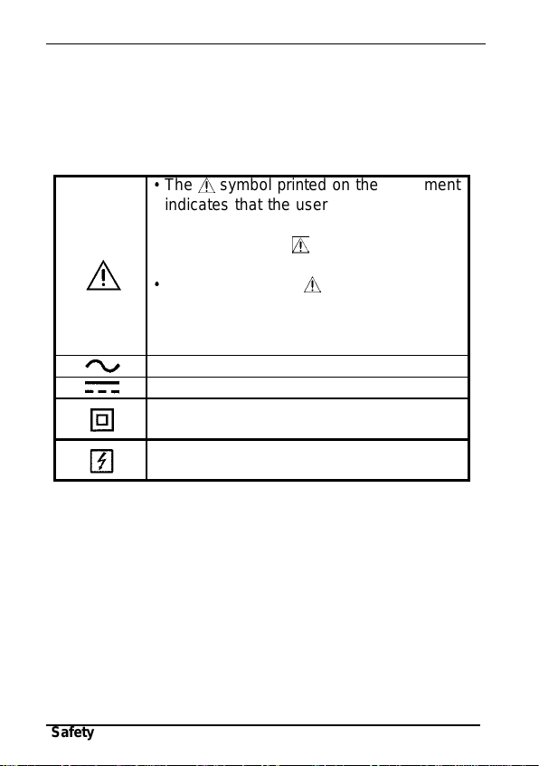
The symbol printed on the instrument
indicates that the user should refer to a
corresponding topic in the manual
(marked with the symbol) before
using the relevant function.
In the manual, the symbol indicates
particularly important information that the
user should read before using the
instrument.
Indicates AC (Alternating Current).
Indicates DC (Direct Current).
Indicates a double-insulated device.
Indicates that the instrument may be connected
to or disconnected from a live circuit.
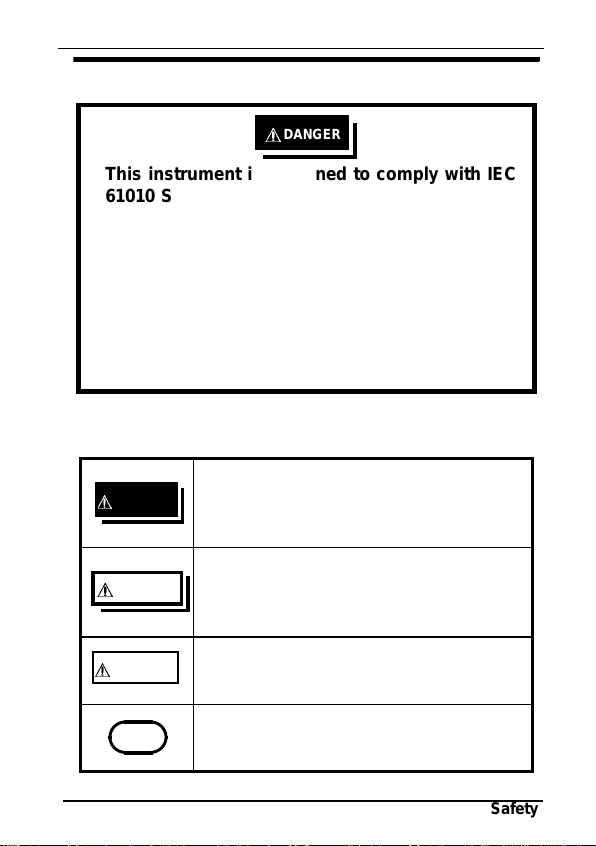
Safety Symbols
This manual contains information and warnings
essential for safe operation of the instrument and for
maintaining it in safe operating condition. Before
using the instrument, be sure to carefully read the
following safety notes.
We define measurement tolerances in terms of rdg.
(reading) and dgt. (digit) values, with the following
meanings:
rdg. (reading or displayed value)
The value currently being measured and indicated
on the measuring instrument.
dgt. (resolution)
The smallest displayable unit on a digital measuring
instrument, i.e., the input value that causes the
digital display to show a "1".

v
―――――――――――――――――――――――――――
Safety
――――――――――――――――――――――――
This symbol indicates that the product
conforms to regulations set out by the
EC Directive.
Indicates the Waste Electrical and
Electronic Equipment Directive (WEEE
Directive) in EU member states.
Symbols for various standards
Measurement categories
This instrument complies with CAT III safety
requirements.
To ensure safe operation of measurement
instruments, IEC 61010 establishes safety standards
for various electrical environments, categorized as
CAT II to CAT IV, and called measurement
categories. These are defined as follows.
CAT II: Primary electrical circuits in equipment
connected to an AC electrical outlet by a
power cord (portable tools, household
appliances, etc.)
CAT II covers directly measuring
electrical outlet receptacles.
CAT III: Primary electrical circuits of heavy
equipment (fixed installations) connected
directly to the distribution panel, and
feeders from the distribution panel to
outlets.
CAT IV: he circuit from the service drop to the
service entrance, and to the power meter
and primary overcurrent protection device
(distribution panel).

vi
―――――――――――――――――――――――――――
Safety
――――――――――――――――――――――――
Using a measurement instrument in an environment
designated with a higher-numbered category than
that for which the instrument is rated could result in
a severe accident, and must be carefully avoided.
Use of a measurement instrument that is not CAT-
rated in CAT II to CAT IV measurement
applications could result in a severe accident, and
must be carefully avoided.

vii
―――――――――――――――――――――――――――
Note on Use
――――――――――――――――――――――――
Note on Use
Follow these precautions to ensure safe operation
and to obtain the full benefits of the various
functions.
Preliminary Checks
Before using the instrument the first time, verify
that it operates normally to ensure that the no
damage occurred during storage or shipping. If
you find any damage, contact your dealer or
Hioki representative.
Before using the instrument, make sure that the
insulation on the voltage cord is undamaged and
that no bare conductors are improperly exposed.
Using the product in such conditions could cause
an electric shock, so contact your dealer or Hioki
representative for replacements. (Model L9635-
01)

viii
―――――――――――――――――――――――――――
Note on Use
――――――――――――――――――――――――
DANGER
To avoid short circuits and potentially life-
threatening hazards, never attach the clamp
sensor to a circuit that operates at more than the
maximum rated voltage to earth.
Clamp sensor should only be connected to the
secondary side of a breaker, so the breaker can
prevent an accident if a short circuit occurs.
Connections should never be made to the primary
side of a breaker, because unrestricted current
flow could cause a serious accident if a short
circuit occurs.
Connect the voltage cords to the instrument first,
and then to the active lines to be measured.
Observe the following to avoid electric shock and
short circuits.:
Do not allow the voltage cord clips to touch two
wires at the same time.
Never touch the edge of the metal clips.
When the clamp sensor is opened, do not allow
the metal part of the clamp to touch any exposed
metal, or to short between two lines.

ix
―――――――――――――――――――――――――――
Note on Use
――――――――――――――――――――――――
WARNING
Do not allow the instrument to get wet, and do not
take measurements with wet hands. This may cause
an electric shock.
To avoid electric shock when measuring live lines,
wear appropriate protective gear, such as insulated
rubber gloves, boots and a safety helmet.
To avoid electric shock when replacing the battery,
first disconnect the voltage cord or clamp from the
object to be measured. After replacing the battery,
replace the cover and screws before using the
instrument.
When replacing the battery, be sure to insert them
with the correct polarity. Otherwise, poor
performance or damage from battery leakage could
result. Replace battery only with the specified type.
Battery may explode if mistreated. Do not short-
circuit, recharge, disassemble or dispose of in fire.
Handle and dispose of batteries in accordance with
local regulations.

x
―――――――――――――――――――――――――――
Note on Use
――――――――――――――――――――――――
CAUTION
Avoid stepping on or pinching the cable, which
could damage the cable insulation.
Keep the cables well away from heat sources, as
bare conductors could be exposed if the insulation
melts.
To prevent an electric shock accident, confirm that
the white or red portion (insulation layer) inside the
cable is not exposed. If a color inside the cable is
exposed, do not use the cable.
Do not exceed the maximum input current rating,
which depends on the frequency of the current
being measured. Be careful about the evolution of
heat, when the input frequency is high.
0
200
400
600
800
1000
1200
10 100 1000 10000 100000
1000
800
600
400
200
010 100 1k 10k 100k
Frequency [Hz]
1200
Maximum input current (Arms)

xi
―――――――――――――――――――――――――――
Note on Use
――――――――――――――――――――――――
CAUTION
If the protective functions of the instrument are
damaged, either remove it from service or mark it
clearly so that others do not use it inadvertently.
Do not store or use the instrument where it could
be exposed to direct sunlight, high temperature or
humidity, or condensation. Under such conditions,
the instrument may be damaged and insulation
may deteriorate so that it no longer meets
specifications.
Keep the clamp jaws and core slits free from
foreign objects, which could interfere with clamping
action.
To avoid damage to the instrument, protect it from
physical shock when transporting and handling. Be
especially careful to avoid physical shock from
dropping. Do not exert excessive pressure on the
clamp sensor or attempt to wedge the sensor into a
tight spot for measurement.
This instrument is designed for use indoors. It can
be operated at temperatures between 0 and 40
without degrading safety.
This instrument is not designed to be entirely
water- or dust-proof. Do not use it in an especially
dusty environment, nor where it might be splashed
with liquid. This may cause damage.
Calibration and repair of this instrument should be
performed only under the supervision of qualified
technicians knowledgeable about the dangers
involved.

xii
―――――――――――――――――――――――――――
Note on Use
――――――――――――――――――――――――
NOTE The indicator appears when battery voltage
becomes low. During which time accuracy cannot
be guaranteed. Replace batteries only with the
specified type.
When replacing the battery, make sure that the
metal battery snap fitting is firmly connected. If the
metal fitting is loose, adjust it and recheck the
connection.
To avoid corrosion from battery leakage, remove the
batteries from the instrument if it is to be stored for
a long time.
Correct measurement may be impossible in the
presence of strong magnetic fields, such as near
transformers and high-current conductors, or in the
presence of strong electromagnetic fields such as
near radio transmitters.

xiii
―――――――――――――――――――――――――――
Organization of This Manual
――――――――――――――――――――――――
Organization of This Manual
Chapter 1
Product Outline
Explains the parts and functions of the instrument.
Chapter 2
Measurement Procedure
Explains how to use the 3286-20 for measurement.
Chapter 3
Specifications
Lists the specifications of the 3286-20 CLAMP ON
AC/DC HiTESTER.
Chapter 4
Battery Replacement
Explains how to replace the battery used to power
the 3286-20.
Chapter 5
Attaching the Hand Strap
Explains how to attach the hand strap, for easy
handling of the instrument in the field.
Chapter 6
Storage in Carrying Case
Explains how to store the instruments in the
carrying case.
Chapter 7
Troubleshooting
Describes how to check before requesting service.
Chapter 8
Service
Explains how to get the instrument serviced.

xiv
―――――――――――――――――――――――――――
Organization of This Manual
――――――――――――――――――――――――

1
―――――――――――――――――――――――――――
Chapter 1 Product Outline
――――――――――――――――――――――――
Chapter 1
Product Outline
1.1 Product Outline
The "3286-20 CLAMP ON POWER HiTESTER" is
designed to provide multiple functions by adopting
a single-chip microcomputer. At any desired point
of a single-phase circuit or three-phase circuit, this
instrument enables the measurement of voltage,
current, power, power factor, phase angle, reactive
power or frequency, and the detection of phase
sequence on live lines.

2
―――――――――――――――――――――――――――
Chapter 1 Product Outline
――――――――――――――――――――――――
1.2 Features
A multi-function microcomputer
The built-in microcomputer offers various functions
in a compact form.
Display of true rms values
The true rms value conversion circuit allows
accurate measurement of currents with distorted
waveforms.
Enables power measurement
When both current and voltage are input
simultaneously, the power factor, phase angle,
reactive factor, as well as power can be measured,
and phase detected.
Enables harmonic measurement
Higher harmonics of current and voltage up to the
20th order can be measured. Moreover, overall
harmonic distortion factors and content can be
displayed.

3
―――――――――――――――――――――――――――
Chapter 1 Product Outline
――――――――――――――――――――――――
Top and Side View
1
2
3
4
5
6
9
8
13
14
10
11
15
16
12
7
17
1.3 Parts and Functions
Table of contents
Other Hioki Power Tools manuals