manuals.online logo
Brands
  1. Home
  2. •
  3. Brands
  4. •
  5. Hitachi
  6. •
  7. Air Conditioner
  8. •
  9. Hitachi RAC-X10CCK User manual

Hitachi RAC-X10CCK User manual

Ins RAS-X10-13-18CCK (CH1)
RAS-X10CCK RAC-X10CCK
+
RAS-X13CCK RAC-X13CCK
+
RAS-X18CCK RAC-X18CCK
+
安装前请详细阅读正确的安装方法。
经销商请按照说明书详细向顾客说明操作方法。
安装工程必须准备的工具
标记是 专用工具
螺丝起子
卷 尺 刀 子
锯 子 切管器六角扳手
电 钻
真空泵扳手或活 动 扳 手
钳 子
泵结合器 喇叭口扩管工具 气体验漏检知器
歧管阀 加注软管
使用前请详细阅读[安全上的注意事项],以正确的使用机体。
在此所示的注意事项,记载着有关安全性上的重要内容,因此以下的注意事项需特别加以注意。
警告 .............安装错误时,可能会造成死亡或重伤的严重后果。 禁止标记。
注意 .............安装不恰当时,也可能会造成严重后果。
安装工作完毕后,请确认运转正常。请向顾客解释使用说明书上的使用及维护方法。请交代顾客把安装说明书及使用说明
书一起保存。
安全上的注意事项
警告
安装时,请给经销商或专门技术人员安装。自己安装可能会造成漏水、触电及火 。
安装工程进行时,请依安装说明书确实进行。安装不完全时,可能会造成漏水、触电及火 。
安装时,请确实将机体安装在能完全耐住机体重量的场所。否则,会有机体落下来的危险。
电气工程时,请依电气设备的规定及安装说明书所示的方法来施工。务必使用专用电路。如电路容量不足或施工不完备, 会引起短路或火 。
室内、外机间的配线需用指定的连接电线确实接续,电线插入端子台后,请确认插入是否确实。插入和固定不完全时,可能会造成过热及火 。
安装工程所需的零件,请务必要用指定的零件。否则,可能会造成机体落下、漏水、触电、火 及更强的震动。
请务必使用所指定的 冷煤配管。否则,可能会造成铜管破裂及故障。
当安装或迁移机体时,除了指定的 冷煤勿让空气或湿气进入冷冻循环内。如果空气等混入后, 会使冷冻循环回路内出现 常高压, 引起破裂或致人负伤。
工程进行时,请确定周围的空气必须流通,若冷煤泄漏而接触到火时,将产生有毒气体。
安装工程完成后,请确定冷煤有无泄漏。若冷煤泄漏在室内而接触到风扇内推动发热器,供热器等的火花时,将产生有毒气体。
未经许可的修改将造成危险。若发生故障,请通知冷气或电器的专门技术人员。不适当的维修可能会造成漏水、触电及火 等。
进行制冷剂回收(抽空)作业时, 要在卸下制冷剂配管之前先停止压缩机。如在运转压缩机, 检修阀处於开放状态下卸下制冷配管, 会吸引空气等, 使冷冻循
环回路内出现 常高压, 引起破裂或致人负伤。
进行安装作业时, 在运转压缩机之前要可靠地安装制冷剂配管。未安装制冷剂配管, 在检修阀处於开放状态下运转压缩机, 会吸引空气等, 使冷冻循环回路
内出现 常高压, 引起破裂或致人负伤。
從電源線到室外機和室內機之間確保要使用接地線。請勿將接地線連接到煤氣管、水管、避雷針或電話之地線等場所。不適當的連接接地線可能
會造成觸電事故
注意
依设置场所状况,有必要安装漏电断电器,室外机的电源线必须安装一个触点间隔 以上的主开关。如未安装漏电断电器,会有触电的危险。
不可安装於有易燃性气体的场所,因为万一气体泄漏在室外机周围的话,可能会发生火 。
安装排水管时,请确认水可否顺利的流出。不正确的安装可导致家具湿透。
請使用IEC認證合格的電源線。
安装场所的选定 (下列几点注意事项,请先得到顾客的同意再安装。)
警告
本机体要安装在支撑充分,不产生振动,强固稳定的地方
。
注意
附近不要有热源,吹出口附近不可有障碍物。
机体的上、左、右方要留有下图 印之尺寸的间隔。
排水要方便,且可以和室外机配管接续在一起的地方。
请勿安装在有易燃性气体泄漏及有蒸气、油烟的场所。
否则有可能引发火苗、引起爆炸或造成树脂的恶化、破损。
为了避免杂讯的影响,请将机体及遥控器,远离电视、收音
机等 以上。
为了避免遥控器有误动作发生,请将遥控器远离高周波机器
及高出力的无线机器。
如有电子点亮型的照明器具, 则信号接收距离有可能会缩
短, 有时还可能接收不到信号。
安装高度离地板至少 。
警告
室外机要安装在能非常耐重的场所,否则噪音和震动会增加。
注意
不要安装於易淋雨或阳光直射得到的地方, 要维持通风良好。
吹出来的风不要正对着动物或植物的地方。
机体的上、左、右、前、后方要留有下图 印之尺寸的间隔,且
至少要留有两面以上是开放的地方。
所吹出来的风和噪音不要成为邻居的困扰。
强风不会吹到的场所
尤其是在大楼楼顶上,风力很强,有可能使室外风扇破损。
请勿安装在有易燃性气体泄漏及有蒸气、油烟的场所。
排水要顺畅的地方。
室外机和连接电线要与电视机、收音机、呼叫机和电话等天线、信
号线和电源线等保持 以上的距离否则有可能因杂声而受影响。
室外机请勿设置在小动物会藏身的地方否则, 小动物进入后,碰触到
内部的电气部件时, 有可能引起故障、冒烟和起火。另外, 请要求
用户保持周围的清洁。
安装室内机 (吹出口) 时, 请将其与火 报警器之间保持米
以上的距离。
室
内
机
室
外
机
1
1
2
3
4
5
1
1
AAA
2
5m
100mm
250mm
100mm
200mm
300mm 200mm
700mm
冷冻机油不耐水,所
以请避免水分进入循
环回路内。
( : mm)
500
750
50
330
310
290
500
698
45
300
282
257
(For )
X10CCK
X13CCK
(For 8CCK1X )
4
20
1
1.
3
ø 65mm
2~5mm
2
“ ”
5mm
15cm
15cm
6
最小
3m
管接頭隔热材
(M4 x )
2. M4 x
(M4 x
<
E4340: G
>
780mm
556mm
450mm
225mm
(260mm)
310mm
70mm 80mm 80mm
50mm以上
50mm
50mm以上
590mm
(230mm)
95mm 95mm
37.5mm 47.5mm
164mm
66.5mm
50.5mm
18mm
65
65
280mm
115mm
42.5mm
12m
•
•
Φ( 4mm)
鉗子
突起部
排水孔
內六角扳手
出水管固定螺釘的孔確實
卡入突臺,用固定螺釘固
定。
排水管固定
螺釘
排水孔 Φ( 4mm)
內六角扳手
移除下麵的蓋板。
•將排水蓋插入到排水孔的位置上,直到插入牢固。
•請使用內六角扳手( 4mm)插入排水蓋的孔內。
(這樣容易安裝排水蓋)
Φ
32
32
32)
G
0.4m 1.2m
1
Ins RAS-X10-13-18CCK (CH 2)
警告
2
(1)
(2)
(3)
2 ~ 3
U
13
配管的切割与扩口
用管子割刀切断,󱜄去掉毛刺。
铜管
整形器
注意
去毛刺
不去掉毛刺, 会引起气体泄漏。
除毛边时,铜管应朝下实施,以避免铜屑进入管内。
铜管
硬模
A
硬模
请在插入扩口螺母后, 进行扩口加工。
注意
注意
3
请让球阀始终处於全开状态。
空气的排出及气体泄漏检查
注意
当拆除室内机的扩口螺母, 首先拆除小口径的螺丝帽。否则大口径的扩口螺母将会冲出。
连接时要防止水分进入。
收紧扩口螺母时务必使用扭矩扳手, 󱜄使用指定的收紧扭矩。
否则会过分收紧扩口螺母, 经过较长时间后, 扩口螺母会开裂, 引起冷媒剂泄漏。
使用控制阀时, 请确认密封圈有否老化, 使用时要避免将手柄拧得过紧。
否则检修阀有可能出现气体泄漏。
出 环保的目的, 希望 用真空抽吸泵进行气洗。 卸下检修阀的盖形螺母。
卸下阀芯的盖形螺母, 接
上充填软管。
将真空
泵接合器与
真空
泵连接,之后将
充气管
与连合器连接。
阀心帽
将小口径检修阀的阀轴旋松 圈, 过 秒
卸下检修阀的加注软管。
将两边的检修阀的阀轴朝逆时针
方向旋转, 直至其轻轻顶住, 打
开冷媒剂通路。(不需要用力旋
转。)
按原样拧紧盖形螺母。最后, 请
进行气体泄漏检查, 确认无气体
泄漏。
关闭歧管阀的手柄 , 将 全开, 运转
(适配器电源 )。
真空
泵运转约分钟,
然后再把旋钮
停止真空
泵运转
(
适配器电源
)
真空抽吸时, 请确认真空
压力两用表的指示值为
。
闭
开始抽真空时,请将粗配管扩口螺母稍
为松开,确认空气是否被吸进去,然后
再将扩口螺母锁紧。
复合压力机
歧管阀
真空
泵
球阀
真空
泵接合器
加注软管
球阀
阀
检修阀本体
六角形扳手
大口径边
检修
阀
的阀头帽
阀心帽
盖形螺母
小口径边
检修
阀
的
控制阀
盖形螺母
气体泄漏检查
右图部份是使用验漏器
来确认冷媒有无从扩口
螺母的接续部份泄出。
泄漏时请增加旋紧度
以防止泄漏。
(请确定使用 验漏器)
设置场所变动时或拆卸时的作业方法
出於环保的目的, 设置场所变动时或拆卸时, 请进行制冷剂
的回收 (抽空)。
以强制制冷运转方式 (参照“强制制冷运转”) 进行
分钟左右的预备运转。
将小口径检修阀的阀轴朝顺时针方向旋转后关闭。
在这一状态下进行 分钟的强制制冷运转, 然后将大
口径检修阀的阀轴朝顺时针方向旋转后关闭。
停止强制制冷运转。
2
配管的接续
从室内机的配管上拆下扩口螺母。这时, 要一边用扳手固定
单头活接头 (阳螺纹侧), 一边用扳手拆下扩口螺丝 (阴螺纹侧)。
弯管加工时请注意不要压扁配管。
在连接部涂上冷媒机油,󱜄对准中心用手拧紧扩口螺母, 然后
用扭矩扳手可靠收紧。
配管的外径 扭矩
小口径
大口径
小口径
大口径
阀心帽
扳手 扭矩扳手
扩口螺母
单头活接头
阴螺纹侧
阳螺纹侧
检修阀 9.52(3/8”)
12.7(1/2”)
9.52(3/8”)
6.35(1/4”)
6.35(1/4”)
34.3-44.1 (450~550)
12.7(1/2”)
44.1-53.99 (350~450)
外径
()
工具
工具
12.7 (1/2”)
6.35 (1/4”)
9.52 (3/8”)
真空泵
全开,
钟后再迅速拧紧。这时请对连接部进行气
体泄漏检查。
RAC-X10CCK
RAC-X13CCK
RAC-X18CCK
请将室外机安装於牢固的地方,以避免震
动及噪音的增大。
决定其位置時請考慮預留配管安裝空間。
拉出侧面护盖时,请抓住捏手,朝下方移
动,使端部的卡钩脱开,然后拉出。装上
护盖时步骤相反。
往下拉
注意
请勿碰触室外机
的吸气口、底面
和铝质散热片故
障可导致受伤。
请使用冷媒R410A的专用工具。
收紧扭矩的大小请根据下表。
1 2
<
E4340:
>
這個製冷功能可以強制執行用於回收冷媒以及檢查故障。
但是不可以長期運行。
<如何開啟>
・冷氣機在停止狀態。
・
<如何關閉>
・再次按壓“應急開關”或者使用遙控器停止運轉。
※強制製冷運轉時,定時燈將兩次閃爍。
應急開關
強制製冷運轉
按壓“應急開關”超過5秒如下圖。
•
•
󰆠󰀊
󰹤󱆎
󰾺󰹤󳋼
󳊪󱇪
󰹩
󰼿󰾺󰹤󳋼󰻟󰹤󳋼󱆎
󰾺󰹤󰂘󳋼󰾺󰹤󳋼󱂇󰹮󰸆󳒍
.2 1.6N m(12 16kgf cm)
󰻟󰽘󰻽󱃼󰻳󰹚󳋼󱣉
󱣉󰼉󰾺󳋼󰖆󱂋󱅊󱉍󰇑󰺳
警告
更换损坏的电缆时,必须使用制造商或维修人员所提供的特许电缆(制造商维修零件)。
连接电线需露出 的芯线,且被覆部要确实压入,然后拉拔各个电线确认有无问题,否则插入不完全时,可能
会使端子台烧损。
务必使用冷气机专用的电路。
请参阅连接电线的安装与电器设备有关的技术基准。
在连接电线留些空间以便方便修理 用缆线固定带固定电线。
AC 1,2
室内连接电线的方法
󰾺󱣉󰼉󰻫󰺳󰇑󰺳
󰇑󰺳󰖆󰁉󰹩󰾺󰹤󳋼
󰷅
󰇑󰺳
󰇑󰺳󰹩

󰹤󱁫
󰹤󰂘󳋼
 󰅣󱄟
󰾺󰹤󳋼


󰹤󰂘󳋼
󱄟󱄞󰅘󰆟󰻫󰺳󰸆󳤑
󰄿󱂘󱉍󰾺󰹤󳋼󰅙󰻫󰺳
󱉍󰖆󰼝󰆟󰹤󰂘󳋼
󰁘󲜄󱃎󱄟
’
󰾺󰹤󳋼
下护盖安取方法
警告
请用缆线固定带固定连接电线
否则雨水会进到电器而造成漏电。此外,不要让
连接电线的部份受到外力而可能会造成发热及火
。
施工后务必装上卸除了的端子座护盖
室外机的接续方法
重要
保险丝
延迟时间保险丝
15A

取下侧盖板与端子座護蓋即可进行。
端子座護蓋
(僅RAC-X18CBK)
連接電線
連接電線
X10CCK、X13CCK X18CCK
接地
1
2
3
接地
1
2
3
1 2 3 1 2 3
1
2
3
1
2
3
3
2
1
31 2
G
HITACHI SPLIT-UNIT AIR CONDITIONER
INSTALLATION MANUAL
Carefully read through the procedures of proper
installation before starting installation work.
The sales agent should inform customers regarding
the correct operation of installation.
THE CHOICE OF MOUNTING SITE (Please note the following matters and obtain permission from customer before installation).
The unit should be mounted at stable, non-vibratory location which can provide
full support to the unit.
INDOOR UNIT
Figure showing the Installation
of Indoor and Outdoor Unit.
The difference in height
between the indoor and
outdoor unit should be
kept below 5m.
The connecting pipe, no
matter big or small,
should all be insulated
with insulation pipe and
then wrapped with plastic
tape. (The insulator will
deteriorate if it is not
wrapped with tape).
The connection of insulated
drain hose.
Please use insulated drain
hose for the indoor piping
(commercial product).
OUTDOOR UNIT
Be sure to
completely
seal any
gap with
putty.
INDOOR UNIT
Indoor Unit Outdoor Unit
RAS-X10C RAC-X10CCK
+
RAS-X13CCK RAC-X13CCK
+
RAS-X18CCK RAC-X18CCK
+
Ins RAS-X10-13-18CCK
WARNING
give clearance
as wide as possible
about 0.45m
Maximum pipe length 12m Minimum pipe length 3m
above 300mm
must not bend
above 50mm
above 250mm above 100mm
above 200mm
above 200mm
above 100mm
above 300mm
above 700mm
SAFETY PRECAUTION
•
Read the safety precautions carefully before operating the unit.
•
The contents of this section are vital to ensure safety. Please pay special attention to the following sign.
WARNING...... Incorrect methods of installation may cause death or serious injury. This sign indicates prohibition.
CAUTION....... Improper installation may result in serious consequence.
Be sure that the unit operates in proper condition after installation. Explain to customer the proper operation and maintenance of the unit
as described in the user’s guide. Ask customers to keep this installation manual together with the instruction manual.
The Length of Indoor Unit
Power Cord
Do not alter the power cord.
Direction of Piping
There are 4 directions
allowed, namely, horizontally
perpendicular to the unit,
vertically down from right,
horizontally out from right and
horizontally out to left.
Don't form the piping
downward at the left of the unit.
about 1. m
about
0.4m
20
Cut away shaded
portion, and finish
the edge of the
opening so that
there is no burr.
Connection
Horizontally
perpendicular
to the unit
No nearby heat source and no obstruction near the air outlet is allowed.
The installation height should be at least 2.3m or more from the floor.
The air blown out of the unit should not point directly to animals or plants.
Do not install at a location where there is flammable gas, steam, oil and smoke.
The refrigerating machine oil
is easily affected by moisture.
Use caution to prevent water
from entering the cycle.
Dimension of Mounting Stand
of the outdoor unit
(unit : mm)
500
750
50
330
310
290
500
698
45
300
282
257
1
Screw for Mounting Plate
Names of Indoor Components
AAA Size Battery
Mounting Plate
QtyNo Component’s Name
1
2
Remote Controller
1
2
3
4
5
1
Heat insulating materials
X10CCK、X13CCK
CK
(EN1)
6
2
(M4 x
X18CCK
<
E4340:
>
INDOOR UNIT
Installation of Mounting Plate, Wall Penetration and Installation of Protection Pipe
1
The draining of the water container inside the indoor unit can be done from the left.
Therefore the mounting plate must be fixed horizontally or slightly tilted towards the
side of drain hose. Otherwise, condensed water may overflow the water container.
Direct Mounting On The Wall
Please use hidden beams in the wall to hold the mounting plate.
Wall Penetration and Installation of Protection Pipe
Drill a ø 65mm hole on wall
which is slightly tilted
towards the outdoor side.
Drill the wall at a small angle.
Cut the protection pipe
according to the wall
thickness.
Empty gap in the sleeve of
protection pipe should be
completely sealed with putty
to avoid dripping of rain
water into the room.
Procedures of Installation and Precautions
Procedures to fix the mounting plate.
1.Drill holes on wall.
2.Fix the mounting plate on
(As shown below)
wall with M4 x 32 screw
)woleberugifninwohssA(
Installation of the Indoor Unit
2
VERTICALLY DOWNWARD PIPING
Preparation
Connect power cord.
Pull out the pipe, power cord and drain hose.
Installation
The upper part of the indoor unit is hanged
on the mounting plate.
The projection at the lower part of the indoor
unit is hooked onto the mounting plate.
Please pull the lower part
of the indoor unit
outwards to check if the
unit is hooked onto the
mounting plate. Improper
installation may cause
vibration and noise.
HORIZONTAL PIPING
Preparation
Change of Drain Hose and Installation Procedures.
Exchange the location of drain hose and drain cap during horizontal piping as shown
in figure below. Be sure to plug in the drain hose until the insulating material folds upon
itself.
HORIZONTAL & DOWNWARD PIPING – MAKING OPENINGS
During horizontal or downward piping, use a knife to cut
openings as shown in figure. Then smoothen the edges
of openings with a file.
INSTALLATION OF COOLANT PIPES AFTER CONNECTION
The coolant pipes should be adjusted to fit into the
holeon the wall and then ready for further connection.
The terminals of 2 connected pipes must be covered
with insulator used for terminal connection.
Connect the power cord.
After adjustment, fit the power cord and pipes into
the space available under the indoor unit.
The rubber strap used for
fixing the insulator should
not be tied with great force.
Otherwise, this will damage
heat insulation and causes
water condensation.
THE CONNECTION OF COOLANT PIPE DURING THE
INSTALLATION OF INDOOR UNIT
Preparation To Install Coolant Pipes
Please fix in the plastic
core after flaring to avoid
plastic chips entering the
pipes.
CAUTION
You are free to choose the side (left or right) for the installation of drain
hose. Please ensure the smooth flow of condensed water of the indoor
unit during installation. (Carelessness may result in water leakage.)
Be sure that the
drain hose is not
loosely connected
or bent.
Be sure that the wire is not
in contact with any metal
in the wall. Please use the
protection pipe as wire
passing through the hollow
part of the wall so as to
prevent the possibility of
damaged by mouse.
Coolant pipes and power cord must be tied together.
The front part of the coolant pipes are at locations
marked with “ ” symbol.
Installation of Drain Hose
3
Pull this to the front
during the connection
of coolant pipes to
ease task.
Installation
Hang the indoor unit onto the mounting plate. Use the temporary
stand at the back of the indoor unit to push its lower part 15cm
forwards.
Place the drain hose through the hole on the wall.
Insulate the connecting portion of coolant pipe with insulator.
Connect the power cord.
After adjustment, thepower cord and coolant pipes are placed
into the space available under the indoor unit.
The projection of indoor unit must hook to the mounting
plate.
Pipe Power cord
Drain hose
Pipe Rubber strap tied with great force
Pipe
below
5mm
Please bend at a small
radius to form an arc
about 15cm
Projection
Temporary stand
Hook
Power cord
Protection
pipe
Drain
hose Connected
terminals
of coolant
pipes
Coolant pipes
Power cord
Heat insulation
pipe
Bending
upwards
Stagment
water
Drain Stagment
water
Openings
Power line, pipe and
drain hose must be
tied together with
plastic tape.
2~5mm
Protection
pipe
Outdoor
Indoor
Seal with
putty
Sleeve of
protection
pipe
WALL
Condensed water may leak out if not inserted properly.
Pipe
support
Pull up the pipe after
bending downward
Transform the piping while holding down the lower portion
of pipe-support by hand.
CAUITON
CAUITON
CAUITON
CAUITON
CAUITON
CAUITON
CAUITON
(M4 x
Mounting Plate
Hook
Coolant pipe
Power Cord
Drain Hose
Protection
Pipe
Lift the body
of the unit
upwards and
then force
it downwards.
Mounting
Plate
Projection
780mm
556mm
450mm
225mm
(260mm)
310mm
70mm 80mm 80mm
50mm以上
50mm
50mm以上
590mm
(230mm)
95mm 95mm
37.5mm 47.5mm
164mm
66.5mm
50.5mm
18mm
65
65
280mm
115mm
42.5mm
•Please use pliers to pull out the drain cap.
(This is an easier way to remove the drain
Drain Hose
Drain cap
•Remove low cover
•Insert drain cap up to the location securely
•Please use hexagonal wrench key(Φ
to insert the drain cap.
(This is an easier way to install the drain cap.)
•Push the pipe deeply until
the drain hose end gets
unit side.
Drain hole
Hexagonal wrench
key (Φ4mm)
Drain hole Hexagonal
wrench key
(Φ4mm)
cap??).
till
the
cap
stops.
4mm)
the insulating section of
over the rib at the indoor
Pliers
Ribs
Screw
32)
32)
G
Ins RAS-X10-13-18CCK_ (EN2) 1
TINUROODTUO
•Please mount the Outdoor unit of stable ground to
prevent vibration and increase of noise level.
•Decide the location for piping after sorting out the
different types of pipe available.
Please face this side (suction
side) of the unit to the wall.
Please remove terminal
cover when connecting
the piping and connecting
cord.
Please remove terminal
cover when connecting
the piping and connecting
cord.
CAUTION
•Do not touch the suction
port, bottom surface, or
aluminum fin of the outdoor
unit.
Failure to do so may cause
an injury.
•When removing side cover, please pull the handle
after undoing the hook by pulling it downward.
Reinstall the side cover in the reverse order of the
removal.
RAC-X10CCK
RAC-X13CCK
Pull downward
Please face this side (suction
side) of the unit to the wall.
RAC-X18CCK
()
12.7 (1/2”)
6.35 (1/4”)
9.52 (3/8”)
Wrench Torque wrench
Flare nut
Half union
Female side
Male side
Remove the flare nut from the pipe of the indoor unit by removing the flare nut
(female side)
with a spanner while holding down the half union (male side)
with a spanner.
Do not crush the pipe while bending it.
Apply refrigerant oil on the connection part. After carrying out the center
alignment and
manual tightening of the flare nut,tighten theflare nut
securely with a torque wrench (spanner).
* Tightening torque must be as shown in the table below.
Outer diameter Torque N•m
)mcfgk()ø(ep ipfo
Small diameter side 6.35 (1/4
”
) 13.7~18.6 (140~190)
Large diameter side 9.52 (3/8
”
) 34.3~44.1 (350~450)
12.7 (1/2
”
) 44.1~53.9 (450~550)
Small diameter side 6.35 (1/4
”
) 19.6~24.5 (200~250)
Large diameter side 9.52 (3/8
”
) 19.6~24.5 (200~250)
12.7 (1/2
”
) 19.6~24.5 (200~250)
Valve core cap 12.3~15.7 (125~160)
Valve
head
cap
•
CAUTION
Remove burr
If burr is not removed, it may cause leakage.
Point the sideto be trimmed downwards during trimming to
prevent copper chips from entering thepipe.
Copper pipe
Die
A
Die
Before flaring,please put on the flare nut.
Please use exclusive tool for refrigerant R410.
Outer Diameter A (mm) Rigid Flaring Tool
For R410A tool For R22 tool
1Preparation of Pipe
Pipe Connection
2
Copper pipe
Trimming tool
Use a pipe cutter to cut the pipe and
remove burr.
Valve head cap
for the service
valve at small
diameter side
Valve head
cap for the
service valve
at large
diameter side
Cap of valve core
Removal Of Air From The Pipe And Gas Leakage Inspection
3
When removing flare nut of the indoor unit, first remove the nut of small diameter
side.
Prevent water from entering into the piping when connecting.
Be sure to tighten the flare nut to the specified torque with a torque wrench.
If the flare nut is overtightened, it may split after sometime and may cause refrigerant leak.
When using a control valve, make sure that the packing is not deteriorated and
avoid excessive
tightening of the handle. Otherwise, gas may leak from the service
valve.
From the viewpoint of global environment
protection, air purge type should be vacuum
pump method.
1
Remove the valve head cap
of the service valve.
Remove the cap of valve core
and
connect the charge hose.
Connect the vacuum pump
adapterto the vacuum pump
and connect the charge hose
to the adapter.
Loosen the spindle of the service valve with small
diameter by 1 / 4 turn and tighten the spindle
immediately after 1 to 2 seconds.
Remove the charging hose from the service valve.
Unscrew the spindle of both the
service valves in anticlockwise
direction to allow the flow of
refrigerant (unscrew halfway).
Tighten the cap of valve head.
Check and make sure that there
is no gas leakage.
Fully tightenthe “ Hi ” shuttle of the
manifold valve and completely unscrew
the “Lo” shuttle. Run the vacuum pump.
(Adapter is switched on)
Make sure the meter
reaches -0.1MPa (-76cmHg)
during pumping. Closed
When pumping starts, slightly loosen
the flare nut to check if air sucked in.
Meter showing pressure
R410A Manifold valve
Vacuum pump
Ball valve
Vacuum pump adapter
Charge hose
Ball valve
Valve
Please leave the ball valve fully
open at all times.
3
4
2
Body of service valve
Hexagonal
wrench key
Cap of valve
head
Cap of valve
head
Cap of
valve core
Works to be done when transferring or removing air conditioner
From the viewpoint of global environmentprotection, refrigerant
should be recovered (pumped down) when the air conditioner is
transferred or removed.
Perform force-cooling operation (refer to “Force-cooling operation”
on page 12) for about 5 minutes as a preliminary operation.
Tighten the spindle of the service valve at small diameter side in
clockwise direction.
Continue the force-cooling operation for another 1-2 minutes, and
then tighten the spindle of the service valve at large diameter side
in clockwise direction.
Stop the force-cooling operation.
Gas Leakage Inspection
Please use gas leakage detector
to check if leakage occurs at
connection of Flare nut as shown
on the right.
If gas leakage occurs , further
tighten the connection to stop
leakage. (Be sure to use R410A
detector.)
After pumping for about 10 -15 minutes,
completely loosen the “ Lo ” shuttle and
switch off the vacuum pump . (Adapter is
switched off)
Otherwise the nut of big diameter side will fly out.
CAUTION
VOMERRIADNASEPIPTNALOOCFONOITALLATSN LAI
LAVOMERRIA
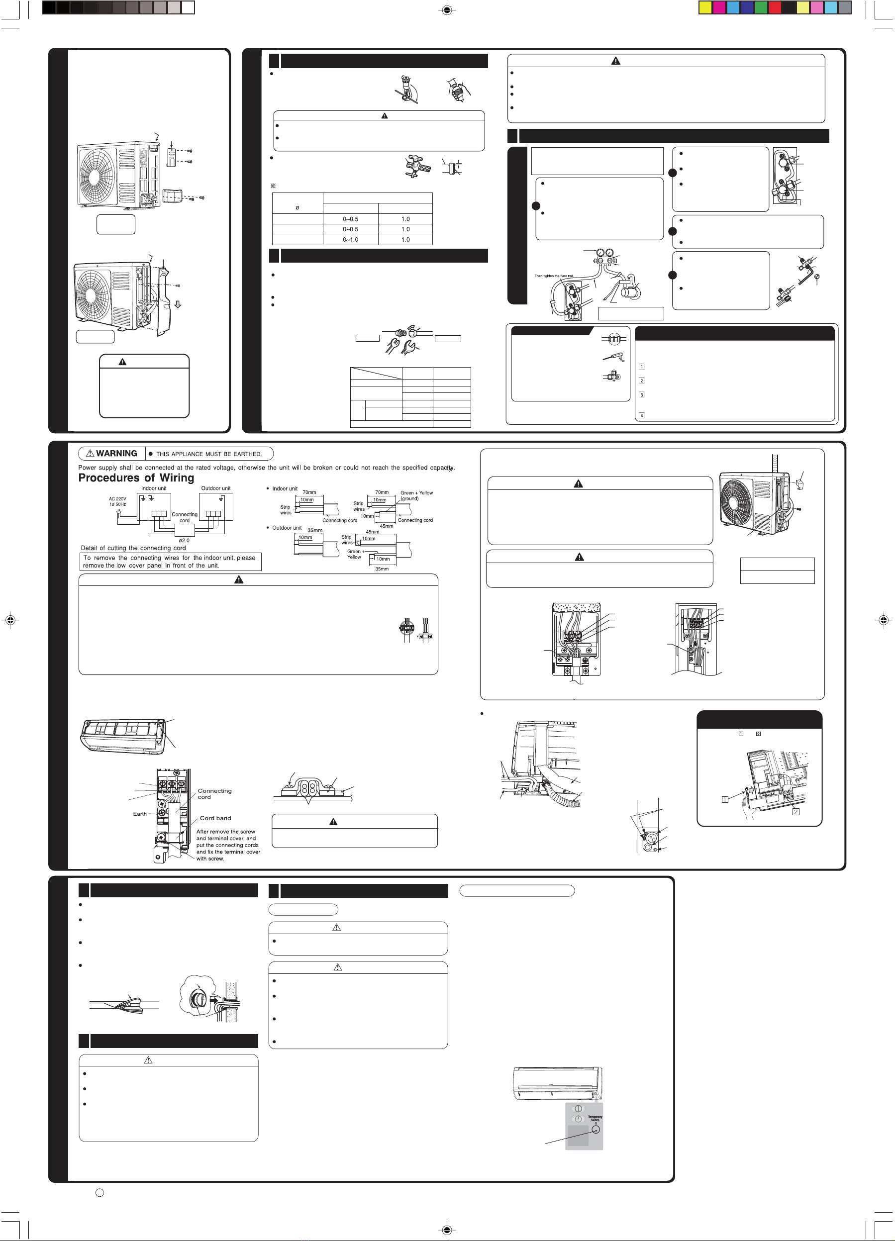
Wiring Of The I ndoor Unit
WARNING
• If the supply cord is damaged, it must be replaced by a special cord (Maker’s service parts) available from the manufacturer
or its service agent.
• The naked part of the wire core should be 10mm fix it to the terminal tightly. Then try to pull the individual wire to check if the
contact is tight. Improper insertion may burn the terminal.
• Be sure to use only wire specified for the use of air-conditioner.
• Please refer to the manual for wire connection, the wiring technique should meet the standard of the electrical
installation.
• Leave some space in the connecting cord for maintenance purpose and be sure to secure it with the cord band.
• Secure the connecting cord along the coated part of the wire using the cord band. Do not exert pressure on the wire as this
may cause overheating or fire.
• There is a AC voltege of 220V between the A and B terminals. Therefore, before servicing, be sure to remove the plug from
the AC outlet.
•For wire connection of the Indoor unit, you need to remove the front cover, the low cover
under the body of the unit and terminal cover.
•Remove the cover from the
terminal base and screw
the cable.
Screw Insulating plate
Cord band
Connecting cord
Securely screw in the power cord and connecting cord so that it will not get
loose or disconnect.
Tightening torque reference value: 1.2 to 1.6 N·m (12 to 16 kgf·cm)
Excessive tightening may damage the interior of the cord requiring replacement.
When putting two connecting cords
through the band.
WARNING
After wiring the indoor unit, make sure to reattach the
terminal cover.
Terminal cover
Terminal cover Screw
Wiring of the Outdoor Unit
Please remove the side cover and terminal cover for wiring connection.
WARNING
•
The connecting cord must be fix with cord band
Otherwise rain water may enter and cause short circuit. Besides, an external
forcemay apply to the connection part of the connecting cord and could result
in heat and fire.
•
The terminal cover and side cover must be installed after work is
done.
Terminal cover
Terminal marking
Cord band
IMPORTANT
Fuse Capacity
1 A time-delay fuse
CAUTION
•
Outdoor supply cords shall not be lighter than polychloroprene
sheathed flexible cord with code designation 60245 IEC 57.
Wiring for the horizontal piping from the right side.
Not to interfere with the
drain hose, fold the cable at
the drain hose side of the
electric box as shown in the
left figure, and pass the
cable just over the electric
box and pull it out.
Cable
Pipe
Drain
Power cord
Electric box
Cable
Power
cord
Pipe
Drain
hose
Form the cable properly so that the
low cover won’t touch the cable in
installation.
Piping and drain hose layout
•Pull at the and in the directionsas
shown by arrows to remove the cover.
Method to remove the low cover
DROCREWOPFONOITCENNOC
Insulation And Maintenance Of Pipe Connection
1
The connected terminals should be completed sealed with
heat insulator and then tied up with rubber strap.
Please tie the pipe and power line together with plastic tape
as shown in the figure of installation of both the indoor and
outdoor units. Then fix their position with holders.
To enchance the heat insulation and to prevent water
condensation, please cover the outdoor part of the drain hose
and pipe with insulation pipe.
Completely seal any gap with putty.
Earth Line And Circuit Breaker
2
Power Source And Operation Test
3
The earth line terminal of the outdoor unit is below the
service valve.
To avoid short circuit, it is necessary to install circuit breaker
depending on the mounting location of the unit.
Do not place earth line near the following objects:
(1) Water pipe
(2) Gas pipe — There is danger of catching fire.
(3) The earth line of lightning conductor and telephone —
short circuit may occur during lightning.
Power Source
Do not alter the plug of power cord.
Do not make extension to the power cord.
Please use a new socket. Accident may occur due to the
use of old socket because of poor contact.
Please plug in and then remove the plug for 2 – 3 times.
This is to ensure that the plug is completely plugged into
the socket.
Keep additional length for thepower cord and do not render
the plug under external force as this may cause poor
contact.
Do not fix the power cord with U-shape nail.
Insulation material for pipe connection
Sleeve of
protection
pipe
Putty
CAUITON
WARNING
CAUTION
NOITALLATSNIFOEGATSLANIF
5
(Only RAC-X18CBK)
<
E4340:
>
Forced cooling operation
The cooling operation can be forcibly performed for collecting
refrigerant and inspecting failures.
Do not perform the forced cooling operation continuously for
long hours,
because the compressor continues to be in operational status,
regardless of room temperature.
<How to start the operation>
・The operation of the unit should be stopped.
・
<How to stop the operation>
・Press and hold the "Temporary operation SW" again.
Or stop the operation using the remote controller.
※During the forced cooling operation,
the "Timer indicator" blinks twice.
Temporary operation switch
Press and hold the "Temporary operation SW"
shown in the right figure for 5 sec.
Connecting cord Connecting cord
EarthEarth
X10CCK、X13CCK X18CCK
1
2
3
1
2
3
1 2 3 1 2 3
1
2
3
1
2
3
3
2
1
31 2
G

This manual suits for next models

5

Other Hitachi Air Conditioner manuals

Hitachi RAS-30CX9S User manual

Hitachi

Hitachi RAS-30CX9S User manual

Hitachi RA-10KDF Specification sheet

Hitachi

Hitachi RA-10KDF Specification sheet

Hitachi RAS-S24H2A User manual

Hitachi

Hitachi RAS-S24H2A User manual

Hitachi RAK-15QPE User manual

Hitachi

Hitachi RAK-15QPE User manual

Hitachi RAI-25QPB User manual

Hitachi

Hitachi RAI-25QPB User manual

Hitachi RAS-25CNH2 User manual

Hitachi

Hitachi RAS-25CNH2 User manual

Hitachi RAM-90NP5A User manual

Hitachi

Hitachi RAM-90NP5A User manual

Hitachi YUTAKI Series User manual

Hitachi

Hitachi YUTAKI Series User manual

Hitachi RAC-18WEF User manual

Hitachi

Hitachi RAC-18WEF User manual

Hitachi RAS-E60YHAB User manual

Hitachi

Hitachi RAS-E60YHAB User manual

Hitachi RAK-25QH8W User manual

Hitachi

Hitachi RAK-25QH8W User manual

Hitachi RAC-35NH5 User manual

Hitachi

Hitachi RAC-35NH5 User manual

Hitachi RAS-07CH5 User manual

Hitachi

Hitachi RAS-07CH5 User manual

Hitachi RAF-25PRA User manual

Hitachi

Hitachi RAF-25PRA User manual

Hitachi RAM-22QH2A User manual

Hitachi

Hitachi RAM-22QH2A User manual

Hitachi RAS-14CH4 User manual

Hitachi

Hitachi RAS-14CH4 User manual

Hitachi air365 Max Series Instruction Manual

Hitachi

Hitachi air365 Max Series Instruction Manual

Hitachi RAM-70NP4A User manual

Hitachi

Hitachi RAM-70NP4A User manual

Hitachi RAS-S18CPA User manual

Hitachi

Hitachi RAS-S18CPA User manual

Hitachi RAS-X18CBT User manual

Hitachi

Hitachi RAS-X18CBT User manual

Hitachi RAK-60NHA1 User manual

Hitachi

Hitachi RAK-60NHA1 User manual

Hitachi air Home 500 User manual

Hitachi

Hitachi air Home 500 User manual

Hitachi RAK-AH10PCASM/RAC-AH10PCASM User manual

Hitachi

Hitachi RAK-AH10PCASM/RAC-AH10PCASM User manual

Hitachi RAS-08AH1 User manual

Hitachi

Hitachi RAS-08AH1 User manual

Popular Air Conditioner manuals by other brands

Daikin EBHQ006BAV3 Operation manual

Daikin

Daikin EBHQ006BAV3 Operation manual

Carrier Fan Coil 42B Installation, operation and maintenance manual

Carrier

Carrier Fan Coil 42B Installation, operation and maintenance manual

Sanyo KS2432 instruction manual

Sanyo

Sanyo KS2432 instruction manual

GE AEC14 Owner's manual and installation instructions

GE

GE AEC14 Owner's manual and installation instructions

Mitsubishi Electric PLA-M100EA installation manual

Mitsubishi Electric

Mitsubishi Electric PLA-M100EA installation manual

Sears Kenmore P/N93SR-D02 owner's manual

Sears

Sears Kenmore P/N93SR-D02 owner's manual

Friedrich WallMaster WS10 Installation and operation manual

Friedrich

Friedrich WallMaster WS10 Installation and operation manual

Samsung AR**HV5D series User's installation guide

Samsung

Samsung AR**HV5D series User's installation guide

Innova IGZCAPS NI Series owner's manual

Innova

Innova IGZCAPS NI Series owner's manual

Sanyo CH0971 Technical & service manual

Sanyo

Sanyo CH0971 Technical & service manual

Haier HC1891VAR Installation & operation manual

Haier

Haier HC1891VAR Installation & operation manual

Friedrich Chill CP18 Installation and operation manual

Friedrich

Friedrich Chill CP18 Installation and operation manual

OMAS Air-Fi AFT7 Installer and User Instruction Manual

OMAS

OMAS Air-Fi AFT7 Installer and User Instruction Manual

TECHWOOD TRF-7008 instruction manual

TECHWOOD

TECHWOOD TRF-7008 instruction manual

Carrier RAV180 installation instructions

Carrier

Carrier RAV180 installation instructions

Whirlpool BHAC1000XS0 Use & care guide

Whirlpool

Whirlpool BHAC1000XS0 Use & care guide

Mitsubishi PQHY-P200YGM-A installation manual

Mitsubishi

Mitsubishi PQHY-P200YGM-A installation manual

Carrier ROOM AIR CONDITIONER operating manual

Carrier

Carrier ROOM AIR CONDITIONER operating manual

manuals.online logo
manuals.online logoBrands
  • About & Mission
  • Contact us
  • Privacy Policy
  • Terms and Conditions

Copyright 2025 Manuals.Online. All Rights Reserved.