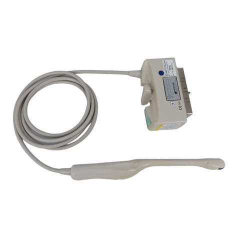
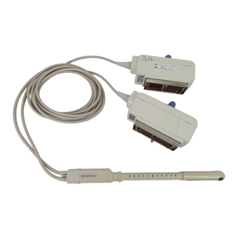
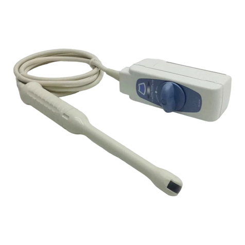
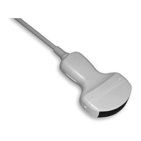
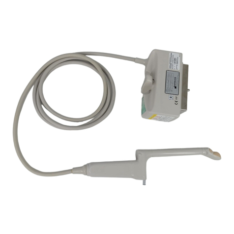
Hitachi S31KP User manual

i
MN1-5831 Rev.5
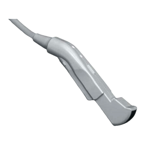
S31KP Probe
Instruction Manual
Specication
MN1-5831 Rev.5
Notes for operators and responsible maintenance personnel
★
Please read through this Instruction Manual as well as the separate Instruction
Manual “Safety (MN1-5986)” and “Cleaning, Disinfection and Sterilization
(MN1-6000)“ carefully prior to use.
★
Keep this Instruction Manual together with the ultrasound diagnostic instru-
ment for any future reference.
© Hitachi, Ltd. 2014, 2017. All rights reserved.

ii
MN1-5831 Rev.5

iii
MN1-5831 Rev.5
Introduction
This is the instruction manual for S31KP probe. The probe is available by connecting to Hitachi’s ultrasound diagnostic
instrument and can be mainly used for observation of human internal organs during surgery.
Prior to use, read this manual as well as the separate instruction manual “Safety” in which information for safe use is
provided.
The probe bears the CE mark but the mark is valid only when the probe is connected to the ultrasound diagnostic
instrument bearing the CE mark.
Symbols used in this document
Safety information is classied into Danger ,Warning Caution, and Note according to the level of hazard. Those terms
are used in the safety information provided to prevent hazards and injuries to the operator or patients.
Danger
Indicates an imminently hazardous situation which, if not avoided, will result in death or serious injury to the
operator or patient.
Warning
Indicates a potentially hazardous situation which, if not avoided, could result in death or serious injury to the
operator or patient.
Caution
Indicates a potentially hazardous situation which, if not avoided, may result in minor or moderate injury to
the operator or patient, or property damage only.
Note
Indicates a strong request concerning an item that must be observed in order to prevent damage or
deterioration of the equipment and also to ensure that it is used efciently.
The type of safety information is indicated by the symbols below.
This symbol means that attention is required.
This symbol means that the described action is prohibited.
This symbol means that the described action is mandatory.

iv
MN1-5831 Rev.5
CONTENTS
1. General Information...................................................................................................................................1
1-1. Intended use...................................................................................................................................................................1
1-2. Classication of ME equipment....................................................................................................................................1
1-3. Standard components ....................................................................................................................................................1
1-4. Option............................................................................................................................................................................2
2. Specications and Parts name....................................................................................................................4
2-1. Specications.................................................................................................................................................................4
2-1-1. Specications of the probe....................................................................................................................................4
2-1-2. Specications of the puncture adapter .................................................................................................................5
2-1-3.Transducer cover when using the probe in neurosurgery application...................................................................5
2-2. Name of each parts........................................................................................................................................................6
3. Preparations before use .............................................................................................................................8
3-1.Start up check of the probe.............................................................................................................................................8
3-1-1. Visual check..........................................................................................................................................................8
3-1-2. Conrmation of cleaning and sterilization ..........................................................................................................8
3-1-3. Operation check....................................................................................................................................................8
3-2. Start up check of the puncture adapter .........................................................................................................................9
3-2-1. Visual check .........................................................................................................................................................9
3-2-2. Mechanical inspection of the puncture adapter...................................................................................................9
3-2-3. Verication of operation.......................................................................................................................................9
3-3. Checking the needle echo ...........................................................................................................................................10
3-3-1. Check setup ........................................................................................................................................................10
3-3-2. Checking the needle echo ..................................................................................................................................11
3-4. Adjusting the needle direction....................................................................................................................................12
3-4-1. When the needle echo does not match the puncture guideline. .........................................................................12
3-4-2. When the needle echo is weak...........................................................................................................................12
3-5. Performing washing and sterilization.........................................................................................................................13
4. Operation..................................................................................................................................................14
4-1. Operation.....................................................................................................................................................................14
4-2. Attaching of the puncture adapter ..............................................................................................................................15
4-3. Setting the needle groove............................................................................................................................................16
v
MN1-5831 Rev.5
This instruction manual contains 5 pages of front matter and 22 pages of the main content.
4-4. Using the needle stopper and the depth gauge ...........................................................................................................16
4-5. Removal of the puncture adapter................................................................................................................................18
4-6. When using the probe for neurosurgery applications ................................................................................................19
4-6-1. How to attach the transducer cover ...................................................................................................................19
4-6-2. How to remove the transducer cover.................................................................................................................19
4-6-3. Puncture .............................................................................................................................................................19
4-6-4. Remove the puncture adapter............................................................................................................................20
4-7. Precautions when using the probe in neurosurgery applications ..............................................................................21

vi
MN1-5831 Rev.5

-1-
MN1-5831 Rev.5MN1-5831 Rev.5
1. General Information
General information for the probe is provided below.
1-1. Intended use
This probe is intended for use by a doctor when placed in direct contact with human internal organs during surgery for
ultrasonic observation.
This probe can also be used for neurosurgery application if our specied transducer cover is mounted on the probe.
Please note that this probe is not allowed to be used for neurosurgery application in Japan. Regarding the precautions for
neurosurgery applications, please refer to the section 4-7.
Please refer to the ultrasound diagnostic instrument instruction manual used with this probe for the probe intended use
information.
Regarding with the connectable instrument, please refer to section 2-1. Specications of this manual.
Warning
Do not use this equipment for other than its intended use.
Otherwise it could cause burns or other injuries to the patient or operator.
1-2. Classication of ME equipment
This probe is classied as follows according to IEC60601-1.
Please refer to the section 2-1 for the range of applied part, the parts treated as applied part, and the range of IPX7.
• Classication based on the degree of protection against electric shock ........ Type BF applied part
• Classication for protection against ingress of liquids .................................. IPX7 (Watertight equipment)
• Operation mode............................................................................................... Continuous operation
• Method of sterilization.................................................................................... Refer to the separate “Instruction Manual
Cleaning, Disinfection and Sterilization”
1-3. Standard components
The standard components of S31KP probe are as follows.
Probe S31KP ...................................................................1 set
Puncture adapter MP-2450-MB........................................................1 set
Needle stopper MP-2477................................................................1 set
Depth gause MP-2450-DG ........................................................1 piece
Storage tray MP-2698................................................................1 set
Adjustment hexagon screwdriver ...............................................................................1 piece
Storage case ...............................................................................1 set
Instruction manual
• Specication MN1-5831..............................................................1 copy
• Safety MN1-5986 .............................................................1 copy
• Cleaning, Disinfection and Sterilization MN1-6000.............................................................1 copy

-2-
MN1-5831 Rev.5MN1-5831 Rev.5
1-4. Option
The following options are available for this probe.
• Reprocessing by liquid detergent, disinfectant or sterilant
Whole the probe is able to immerge into the liquids by putting the connector of the ultrasound probe to the
waterproof case WP-001 as below table.
Precautions about the waterproof case, please refer to the instruction manual.
Accessory for reprocessing by liquid detergent, disinfectant or sterilant
Product Name Product No.
Waterproof case WP-001

-3-
MN1-5831 Rev.5MN1-5831 Rev.5
2. Specications and Parts name
2-1. Specications
2-1-1. Specications of the probe
Application regions: Intraoperative diagnosis
Neurosurgery application, see 4-7 for precautions
Type of patient contact: Intraoperative
Neurosurgical, see 4-7 for precautions
Connectable instruments: ARIETTA 70, ARIETTA 60, Noblus, ARIETTA Precision
NOTE:
At the time of publication of this manual, the connectable diagnostic ultrasound
instrument or instrument software version available with this probe is different for each
country, please refer to the instrument instruction manual or contact your local Hitachi
representative.
Field of view: 90°
Frequency: 5.0 MHz
Cable length: 2.5 m
Service life: 3 years
Applied part: Probe tip including ultrasonic radiation part, see the section 2-2
Parts treated as applied parts: Cable up to 0.2 m length from the probe tip
IPX7 range: See Figure 1 (In case that not putting the waterproof case to the ultrasound probe
connector)
In case that putting the waterproof case to the ultrasound probe connector, whole the
probe from the tip of the ultrasound probe to the connector with Waterproof Case WP-
001 is IPX7. range
Tolera nce: Refer to the instruction manual of the ultrasound diagnostic instrument
External dimensions: See Figure 1
12 12
109
1000
IPX7 range
Applied part
Figure 1 External View
Unit: mm
Cable length
Remarks: The tolerance for the dimensions is ±10%.

-4-
MN1-5831 Rev.5MN1-5831 Rev.5
2-1-2. Specications of the puncture adapter
Material Stainless steel
Usable puncture needle size and diameter 8G(4.2±0.3mm) to 24G(0.55±0.1mm)
Service life 3 years
External dimensions As shown in the gure below.
Remarks
The dimensions are within ±10% of the indicated values.
Figure 2 External View of the puncture adapter
2-1-3.Transducer cover when using the probe in neurosurgery application
CIVCO Transducer cover 610-956 , 610-956-EU
This transducer cover can be used in neurosurgery applications and it is Pyrogen free.
If you are unable to obtain the transducer cover locally, please contact your local Hitachi Systems representative.

-5-
MN1-5831 Rev.5MN1-5831 Rev.5
2-2. Name of each parts
(1) Probe
The name of each parts is shown in Figure 3 and explanation for each parts is listed in Table 1.
Cable
Probe tip
Front mark Ultrasonic radiation part
Connector
Figure 3 Name of each parts
Table 1 Name of each parts and explanation
Name Explanation
Ultrasound radiation part Electronic convex transducer is integrated.
Front mark A small round protrusion indicates the front direction on the display.
This mark also helps attach the puncture adapter.
Probe tip This is the grip of the probe.
Cable Ultrasonic signal is transferred through the cable.
Connector The connector is the part which is connected to the ultrasound
diagnostic instrument.
Caution
Do not pull, bend, twist, or apply excessive force to the cable.
The probe may malfunction due to cable disconnection.
Do not subject the ultrasonic radiation part to hard impact.
The impact may cause damage to the transducer, and that results in noise or no echo in the image.
In most cases, the ultrasonic radiation part itself is not damaged because the part is made of elastic material.

-6-
MN1-5831 Rev.5MN1-5831 Rev.5
(2) Puncture adapter
The name of each parts is shown in Figure 4 and explanation for each parts is listed in Table 2.
Release lever
Fixing knob
Lever locking knob
Fixed stand attaching hole
Needle groove setting knob
Figure 4 Name of each parts of puncture adapter
Table 2 Name of each parts and explanation of puncture adapter
Name Explanation
Fixing knob
This is used to x the puncture adapter to the probe.
Turning clockwise tightens the screw.
Tighten the screw securely referring to 4-2 “Attaching of the puncture
adapter”.
Needle groove setting knob
Adjust the needle groove width to the diameter of a puncture needle to
be used.
Turning clockwise widens the needle groove.
Refer to the section 4-3 “Setting the needle groove “.
Lever locking knob
This is used to prevent unintentional movement of the release lever.
Securely tighten this knob by turning clockwise if the puncture needle
does not neet to be released.
Release lever By pressing the release lever, the needle groove widens and the
puncture needle can remove from the puncture adapter.
Fixed stand attaching hole Used to x a puncture adapter to a stand used for puncturing.

-7-
MN1-5831 Rev.5MN1-5831 Rev.5
3. Preparations before use
This chapter describes preparations needed to use the probe safely. Please prepare the probe and the puncture adapter
prior to each use by following the instructions below.
3-1.Start up check of the probe
3-1-1. Visual check
Visually check the probe tip, ultrasonic radiation part, cable, and connector.
If any holes, indentations, abrasion, cracks, deformation, looseness, discoloration, or other abnormalities are
found, do not use the probe.
Check also the options as necessary.
3-1-2. Conrmation of cleaning and sterilization
Conrm that the probe is certainly cleaned and sterilized. The degree of reprocessing depends on the intended
use. Please refer to the separate Instruction Manual “Cleaning, Disinfection and Sterilization“ for cleaning and
sterilization procedure.
3-1-3. Operation check
Connect the probe to the ultrasound diagnostic instrument and check that the displayed scan type and frequency
correspond to those of the probe. Check also that there is no abnormality in the image.
Remark:Please refer to the documentation supplied with the ultrasound diagnostic instrument for how to connect the
probe and information displayed on the monitor.
If the probe is operated in still air, brightness on the top of the image may be non uniform, but this does not
affect the performance of the probe.
Warning
Make preparations prior to each use.
The operator and the patient may be injured if the equipment has any abnormality.
If any abnormality is found in the equipment, stop using it and contact our ofce written on the back
cover.
Caution
Do not use the probe if the displayed scan type and frequency do not correspond to those of the probe.
Incorrect acoustic output can result in burns or other injuries to the patient. Contact our ofce written
on the back cover.

-8-
MN1-5831 Rev.5MN1-5831 Rev.5
3-2. Start up check of the puncture adapter
3-2-1. Visual check
Check the punctute adapter for any of the abnormal conditions below.
• Abnormalities seen in visual such as deformation, cracks, abnormal gaps, damage, foreign matter adhering,
severe discoloration.
3-2-2. Mechanical inspection of the puncture adapter
Check that the puncture adapter mechanism while attached to the probe.
• The screws (incl. Fixing knob, Needle groove setting knob and Lever locking knob) have no abnormalities
such as looseness, backlash and immobility.
• When the release lever is pressed with the lever locking knob loosen, the puncture needle can be removed
from the puncture adapter.
• The release lever does not move when the lever locking knob is tightened securely.
The puncture adapter is rmly attached to the probe.
• A puncturing needle that passes through the needle groove moves smoothly in the puncturing direction.
Remark:See section 4-2 “Attaching of the puncture adapter”
3-2-3. Verication of operation
When puncturing under the ultrasonic guide, for safety reason, it is also recommended that you have a full
understanding of ultrasound diagnostic characteristics and conduct practice beforehand using a tub or similar
object.

-9-
MN1-5831 Rev.5MN1-5831 Rev.5
3-3. Checking the needle echo
3-3-1. Check setup
(1) Required items
Tub (Depth of 20 cm or more)
Warm water 40°C (104°F)
Thermometer
Probe
Puncture adapter
Puncture needle 18G (length of 150 mm to 200 mm)
(2) Preparation procedure
1. Put warm water at 40°C (104°F) into the tub.
Use a thermometer to check the water temperature.
2. Refer to section 4-2 “Attaching of the puncture adapter” and attach the puncture adapter to the probe, and
attach the puncture needle into the needle groove.
Check that the puncture needle has no bending or other defects.
3. Connect the probe to the ultrasound diagnostic instrument.
Turn on the ultrasound diagnostic instrument to display the puncture guideline on the monitor screen.
Remarks:For details of the puncture guideline, refer to the instruction manual of the ultrasound diagnostic
instrument.
Caution
Use warm water at 40°C in the check of the needle echo.
In the actual puncture operation, the needle echo and guideline may not match and this could result in
puncturing of an unintended body part. It is well-known that the acoustic characteristics of water at 40°C
(104°F) are the most similar to those of the human body.

-10-
MN1-5831 Rev.5MN1-5831 Rev.5
3-3-2. Checking the needle echo
(1) Dip the probe tip into the warm water so that the needle echo is displayed.
Probe
Puncture adapter
Tub
Water of 40℃
Figure 5 Checking needle echo 1
(2) Check the following points.
• The needle echo matches with the puncture guideline.
• The echo of the entire needle is displayed fully and clearly.
Image on the monitor screen
Needle echo
Puncture guide line
Figure 6 Checking needle echo 2
(3) If the needle echo does not match the puncture guideline or is weak, refer to section 3-4 “Adjusting the
needle direction”, and ne-tune the needle direction so that it is displayed in the optimum state.

-11-
MN1-5831 Rev.5MN1-5831 Rev.5
3-4. Adjusting the needle direction
If the needle echo needs to be adjusted, see section 3-3-1 “Check setup”, and perform the adjustment below.
After adjustment, tighten the screws securely, and check that they have no backlash.
3-4-1. When the needle echo does not match the puncture guideline.
As shown below, use the supplied adjustment hexagon screwdriver to loosen the needle angle adjusting screw
and align the needle echo with the puncture guideline.
Needle angle adjusting screw
Adjustment hexagon
screwdriver
Loosen
Puncture
needle
Figure 7 Adjustment of needle angle
3-4-2. When the needle echo is weak
As shown below, use the supplied adjustment hexagon screwdriver to loosen the needle echo level
adjusting screw and display the entire needle echo with the strongest signal.
Loosen
Needle echo level
adjusting screw
Adjustment hexagon
screwdriver
Figure 8 Adjustment of needle echo level

-12-
MN1-5831 Rev.5MN1-5831 Rev.5
3-5. Performing washing and sterilization
(1) Before use, wash and sterilize the puncture adapter, the needle stopper and the depth gauge.
Please refer to the instruction manual of the puncture adapter.
(2) Wash and sterilize the probe to be used in accordance with its usage purpose.
Warning
The equipment must be washed and sterilized before use.
Be sure to always properly wash and sterilize after use.
Otherwise, an infection can occur. Note that the equipment is not sterilized when shipped from the factory.
Before using the equipment for the rst time, be sure to wash and sterilize it.

-13-
MN1-5831 Rev.5MN1-5831 Rev.5
4. Operation
This chapter describes the operation of the probe, how to attach/release puncture adapter and how to mount/remove the
transducer cover for neurosurgery application.
4-1. Operation
Place the ultrasonic radiation part of the probe onto the inner organ surface during surgery. An image of the region of
interest is displayed on the monitor of the ultrasound diagnostic instrument. For details on displaying and adjusting the
screens, see the documentation supplied with the ultrasound diagnostic instrument.
Caution
Do not operate the probe with excessive force.
Use with excessive force could result in injury to the patient.
Scan for minimum time necessary at the lowest possible acoustic output.
Acoustic output may affect the patient’s internal tissues.
For details about the acoustic output, please refer to the documentation supplied with the ultrasound
diagnostic instrument.
Do not touch the connector terminal pin of the probe.
Electrostatic discharge may result in malfunction of the probe.
Do not touch the electronic probe connecting socket of the diagnostic instrument and the patient at the same
time.
It can cause electric shock to the patient.

-14-
MN1-5831 Rev.5MN1-5831 Rev.5
4-2. Attaching of the puncture adapter
(1) Align the front mark and the protrusion on the probe with the puncture adapter guide hole and the puncture guide
groove, then attach the puncture adapter to the probe.
Front mark
Protrusion
Guide hole
Fit
Fit
Guide groove
Figure 9 Attachment and xture of puncture adapter 1
(2) Check that the front mark and the protrusion on the probe fit the guide hole and guide groove on the adapter
respectively. Then, tighten the xing knob.
Fixing
knob
Tighen the knob
Figure 10 Attachment and xture of puncture adapter 2
Table of contents
Other Hitachi Medical Equipment manuals

Hitachi
Hitachi C252 User manual

Hitachi
Hitachi C22P User manual

Hitachi
Hitachi L43K User manual

Hitachi
Hitachi S211 User manual

Hitachi
Hitachi EUP-OL334 User manual

Hitachi
Hitachi L441 User manual

Hitachi
Hitachi VC35 Probe User manual

Hitachi
Hitachi EUP-L74M User manual

Hitachi
Hitachi EUP-LV74 User manual

Hitachi
Hitachi C41RP User manual

Hitachi
Hitachi EUP-L65 User manual

Hitachi
Hitachi C251 User manual

Hitachi
Hitachi OPTIGEN AP 720STM User manual

Hitachi
Hitachi C42T User manual

Hitachi
Hitachi UST-5710-7.5 User manual

Hitachi
Hitachi AP 720S User manual

Hitachi
Hitachi UST-9124 User manual

Hitachi
Hitachi S121 User manual

Hitachi
Hitachi SCENARIA User manual

Hitachi
Hitachi EUP-CC531S User manual