manuals.online logo
Brands
  1. Home
  2. •
  3. Brands
  4. •
  5. Hitachi
  6. •
  7. Saw
  8. •
  9. Hitachi C 8FC User manual

Hitachi C 8FC User manual

Other manuals for C 8FC

2

Other Hitachi Saw manuals

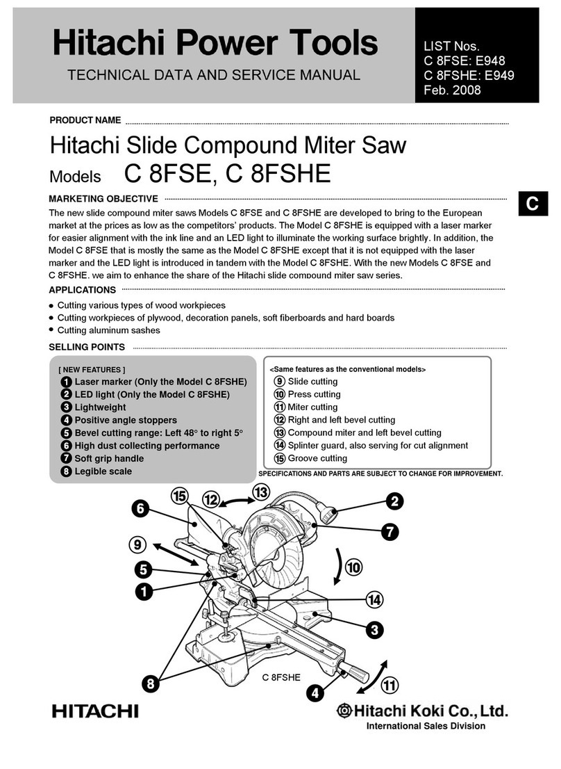
Hitachi C 8FSE User manual

Hitachi

Hitachi C 8FSE User manual

Hitachi CC 14 Operator's manual

Hitachi

Hitachi CC 14 Operator's manual

Hitachi CR 13VC Manual

Hitachi

Hitachi CR 13VC Manual

Hitachi CD 7SA Troubleshooting guide

Hitachi

Hitachi CD 7SA Troubleshooting guide

Hitachi CR 13VC User manual

Hitachi

Hitachi CR 13VC User manual

Hitachi CD 12F User manual

Hitachi

Hitachi CD 12F User manual

Hitachi DS 18DBL User manual

Hitachi

Hitachi DS 18DBL User manual

Hitachi C 10FCB User manual

Hitachi

Hitachi C 10FCB User manual

Hitachi C 12YB User manual

Hitachi

Hitachi C 12YB User manual

Hitachi CJ 10DL User manual

Hitachi

Hitachi CJ 10DL User manual

Hitachi C 10FL Operator's manual

Hitachi

Hitachi C 10FL Operator's manual

Hitachi C 6DC User manual

Hitachi

Hitachi C 6DC User manual

Hitachi C12LCH Manual

Hitachi

Hitachi C12LCH Manual

Hitachi C75T Troubleshooting guide

Hitachi

Hitachi C75T Troubleshooting guide

Hitachi C 7ST User manual

Hitachi

Hitachi C 7ST User manual

Hitachi C 9U3 User manual

Hitachi

Hitachi C 9U3 User manual

Hitachi CR 13V2 User manual

Hitachi

Hitachi CR 13V2 User manual

Hitachi C 6 User manual

Hitachi

Hitachi C 6 User manual

Hitachi C10LA - 10" Cabinet Saw User manual

Hitachi

Hitachi C10LA - 10" Cabinet Saw User manual

Hitachi C 12RSH2 User manual

Hitachi

Hitachi C 12RSH2 User manual

Hitachi C 6U2 User manual

Hitachi

Hitachi C 6U2 User manual

Hitachi C 13U User manual

Hitachi

Hitachi C 13U User manual

Hitachi C 10FS User manual

Hitachi

Hitachi C 10FS User manual

Hitachi C 10FR User manual

Hitachi

Hitachi C 10FR User manual

Popular Saw manuals by other brands

General 90-125 M1 Setup & operation manual

General

General 90-125 M1 Setup & operation manual

Scheppach sd1600v instruction manual

Scheppach

Scheppach sd1600v instruction manual

Skil 5750 Operating/safety instructions

Skil

Skil 5750 Operating/safety instructions

Black & Decker Sawcat 3027-10 owner's manual

Black & Decker

Black & Decker Sawcat 3027-10 owner's manual

Uni-Vent PS-COS12 manual

Uni-Vent

Uni-Vent PS-COS12 manual

Bosch GKS 190 Professional Original instructions

Bosch

Bosch GKS 190 Professional Original instructions

Black & Decker KS999E user guide

Black & Decker

Black & Decker KS999E user guide

Ingco CS18528 instruction manual

Ingco

Ingco CS18528 instruction manual

IMET BS 300/60 SHI Instructions for use

IMET

IMET BS 300/60 SHI Instructions for use

Scheppach Deco-flex instruction manual

Scheppach

Scheppach Deco-flex instruction manual

CMi C-KGS-1450/210 Original instructions

CMi

CMi C-KGS-1450/210 Original instructions

Bosch GCO 14-2 operating instructions

Bosch

Bosch GCO 14-2 operating instructions

Clarke CCS185B Operation & maintenance instructions

Clarke

Clarke CCS185B Operation & maintenance instructions

Makita 2107F instruction manual

Makita

Makita 2107F instruction manual

Holzmann DKS 21PRO user manual

Holzmann

Holzmann DKS 21PRO user manual

RIDGID BS1400 owner's manual

RIDGID

RIDGID BS1400 owner's manual

Optimum OPTisaw CS 275 operating manual

Optimum

Optimum OPTisaw CS 275 operating manual

Makita BPB180 instruction manual

Makita

Makita BPB180 instruction manual

manuals.online logo
manuals.online logoBrands
  • About & Mission
  • Contact us
  • Privacy Policy
  • Terms and Conditions

Copyright 2025 Manuals.Online. All Rights Reserved.

--- 1 ---
MODEL C 8FC
1. PRECAUTIONS IN DISASSEMBLY AND REASSEMBLY:
Points requiring particular attention in disassembly and reassembly are described below. The circled numbers in
the descriptions correspond to the item numbers in the Parts List and exploded assembly diagrams.
[CAUTION]
Prior to attempting disassembly (including replacement of the saw blade), ensure that the machine is
turned OFF and the plug is disconnected from the power source.
1-1. Disassembly:
No. Disassembly
of Section Method of Disassembly Tools Required
1 Gear Case
Section
A. Remove the M6 x 22 Knob Bolt [27], and take off Guard (A) [17].
B. With the standard accessory 10 mm Box Spanner, loosen the two M6 x
30 Bolts (w/Washers) [31], and take off the Fence [32] and Clamp
Piece [30]. As the Clamp Piece is very small, be very careful not to
lose it.
10 mm Box
Wrench
(Standard
Accessory)
--- 2 ---
No. Disassembly
of Section Method of Disassembly Tools Required
2
3
Hinge and
Hinge
Holder
Section
Turn Table
and Base
Section
C. Loosen the M5 x 10 Hex. Socket Set Screw [16] which fixes the Gear
Case Pin [41] at the upper side of the Hinge [8], and then remove the
M5 x 12 Hex. Socket Hd. Bolt [6] from the side of the Hinge.
As the M5 x 12 Hex. Socket Hd. Bolt serves as the upper limit stopper
for the Gear Case [51], the Gear Case will move upward when it is
removed so exercise caution.
D. Extract the Gear Case Pin [41] by tapping it gently while supporting the
Gear Case section.
Then, after removing the two M5 x 20 Hex. Socket Hd. Bolts
(w/Flange) [9], the Hinge Arm Ass'y [10] can be disassembled from the
Hinge [8].
A. Loosen and remove the Tension Lever [1] (left-hand threaded), and
extract the M10 x 60 Bolt (Left Hand) [28] from the Hinge [8].
B. Loosen the M5 x 10 Hex. Socket Set Screw [16] which fixes the Hinge
Pin [14] at the lower side of the Hinge [8], and tap gently on the Hinge
Pin [14] with the plastic hammer to extract it. The Hinge [8] can then
be removed.
C. Remove the three Hex. Socket Hd. Bolts (w/Flange) [4] which fix the
Hinge Holder [15] to the Turn Table [35]. The Hinge Holder [15] can
then be removed.
Removing the Hinge Holder will expose the Clutch Spring [24] which
presses the miter-cutting stopper D9.53 Steel Ball [25] against the
surface of the Base [37]. Be very careful not to lose the Clutch Spring.
A. Remove the Table Insert [33] from the Turn Table [35] by lifting it
upward from the Turn Table with the minus screwdriver.
B. With the 10 mm Box Wrench, remove the M6 x 10 Nylock Bolt [40]
from the lower side of the Base [37], and extract the Table Pin [34]
which fixes the Turn Table [35] to the Base [37]. The Turn Table [35]
can then be removed. When the Turn Table [35] is removed, the miter
stopper D9.53 Steel Ball [25] will remain on the Base [37]. Be very
careful not to lose the Steel Ball.
Hexagon Bar
Wrench
Plastic Hammer
Hexagon Bar
Wrench Plastic
Hammer
Minus Screw-
driver
10 mm Box
Wrench
(Standard Ac-
cessory)
--- 3 ---
No. Disassembly
of Section Method of Disassembly Tools Required
4Saw Cover
,
Lever (A)
Safety Cover
,
the Spindle
Ass'y, and
Washer (C)
A. Remove the M5 x 12 Machine Screw [48] and take off Washer (B)
[108], Lever (A) [106], and Spring (C) [107].
B. Remove the three M5 x 12 Flat Hd. Screws [103], and remove the Saw
Cover Ass'y [104] from the Gear Case [51].
C. With the 10 mm Box Wrench, remove the M7 x 17.5 Bolt (Left Hand)
[102]. The Washer [39], Washer (C) [101], Saw Blade [100], and
Washer (C) [99] can then be taken off in that order.
D. Remove the two M4 Flat Hd. Screws (w/ Toothed Lock Washers) [98].
The Cover [97] can then be taken off.
E. When Return Spring (B) [95] which is attached to the Safety Cover [96]
is removed, the Safety Cover can be taken off.
F. Remove the two M5 x 35 Flat Hd. Screws (w/Toothed Lock Washers)
[94], and remove the Cover Holder [93] from the Gear Case [51].
Then, tap the Gear Case lightly with the plastic hammer to loosen and
remove the Spindle Ass'y [89].
Philips Hd. (Plus)
Screw driver
10 mm Box
Wrench (Stan-
dard Accessory)
Plastic Hammer
--- 4 ---
No. Disassembly
of Section Method of Disassembly Tools Required
5Housing
Ass'y,
Switch, Ar-
mature
Ass'y, and
Stator Ass'y
A. Disassembly of the Armature Ass'y:
(1) Remove the Brush Caps [82] and the Carbon Brushes [83] (two
each). Then, remove the three M5 x 50 Machine Screws
(w/Washers) [66], and the M5 x 12 Machine Screw [48] which fixes
the Cord [47] to the Gear Case [51]. The Housing Ass'y [79] with
the Handle Cover [69] attached to it can then be removed from the
Gear Case [51].
(2) Extract the ArmatureAss'y [74] from the Housing Ass'y [79].
B. Remove the three D4 x 25 Tapping Screws [61], and take off the
Handle Cover [69]. From the Switch [68], disconnect the leadwires
from the Stator Ass'y [70] and the Cord [47].
C. Disassembly of the Stator Ass'y:
(1) Remove the D4 x 25 Tapping Screw (w/Washer ) [61] and the D4 x
20 Tapping Screw (w/Washer) [64] from the Housing Ass'y [79],
and take off the Tail Cover [65].
(2) Disconnect the two Stator Ass'y Brush Terminals [71] from the
Brush Holders [81]. Then, with the nippers, cut off the single
leadwire from the Stator Ass'y [70] that is pressure connected at
the Connector [86].
(3) Remove the two M5 x 60 Machine Screws (w/Washers) [72] which
fix the Stator Ass'y [70], and tap gently on the Gear Case [51]
mounting side of the Housing Ass'y [79] with the plastic hammer to
loosen and extract the Stator Ass'y [70].
Minus Screw-
driver
Phillips Hd.
(Plus) Screw-
driver
Minus Screw-
driver
Phillips Hd.
(Plus) Screw-
driver
Phillips Hd.
(Plus) Screw-
driver
Minus Screw-
driver
Nippers
Plastic Hammer
--- 5 ---
No. Disassembly
of Section Method of Disassembly Tools Required
6
7
8
Stopper Pin
Vise Ass'y
Guard
Section
A. Following the proce-
dures described
above, perform
disassembly as far as
removal of the Arma-
ture Ass'y [74].
B. With the pliers, ex-
tract the Retaining
Ring (E-Type) [46]
from the Stopper Pin
[52], and take off the
Stopper Pin [52] and
the Spring [45].
A. Remove the M6 x 11
Knob Bolt [54], and
remove the Vise
Shaft [60] from the
Vise Ass'y [53].
B. Remove the M4 x 10
Machine Screw [59],
and take off the M10
x 66 Knob Bolt [55]
and the Vise Plate
[58].
A. As described in
Paragraph 1-(1)-A,
take off Guard (A)
[17].
B. Remove the two
M4 x 6 Flat Hd.
Screws (Brass) [19],
and remove Guard
(B) [20] by pulling it
forward.
Pliers
Phillips Hd.
(Plus) Screw-
driver
Phillips Hd.
(Plus) Screw-
driver
--- 6 ---
1-2. Reassembly:
Reassembly can be accomplished by following the disassembly producures in reverse. However, special
attention should be given to the following items.
(1) Prior to reassembly, measure the insulation resistance of theArmature Assembly, Stator Assembly, Switch and
other electrical components with a 500V DC Megohm Tester, and confirm that the insulation resistance of each
part is more than 5MΩ,
(2) When assembling the Hinge [8] and the Gear Case [51], apply 2 grams of grease (Hitachi Motor Grease
No. 29, Code No. 930-035, is recommended) to the oil groove of the Hinge.
(3) When replacing the Spring [7], apply 2 grams of grease (same grease is recommended) to its inner
circumference.
(4) When replacing the Liner [36], assemble it into the unit as illustrated in Fig. 1. During reassembly, apply 6
grams of grease (same grease recommended) to the Liner-sliding surface of the Turn Table [35].
Turn Table
Liner
Ensure that the Liner fits into the
groove portion of the Turn Table.
Base
Fig. 1
(5) If the M6 x 10 Nylock Bolt [40] at the bottom of the Base [37] is tightened excessively, the movement of the
Turn Table [35] will become sluggish and heavy; if the bolt is loose, it will cause vibration and looseness of the
Turn Table which will reduce cutting accuracy. Adjust the M6 x 10 Nylock Bolt so that the Turn Table moves
smoothly with minimal play and vibration.
--- 7 ---
1-3. Wiring:
Carefully ensure that wiring is accomplished as illustrated below. As incorrect wiring will result in lack of rotation,
reverse rotation or other malfunctions, close attention is absolutely necessary.
(1) Wiring Diagram:
Stator Assembly
Black
Switch
OFF
Armature Assembly
Noise Suppressor
(Condenser)
Green/
Yellow
Stator
Core
Outer
Circumference
Black
Figures in circled numbers indicate
terminal numbers of the Switch.
1
3
2
4
(2) Leadwire Arrangements:
Noise Suppressor (Condenser)
Insert leadwires into the
grooves of the Housing.
Green/Yellow
Terminal
Switch Black
Brush Holder
Red
Cord Assembly
Cord Clip
Cord Armor
1-4. Checking Insulation:
When connecting leadwires, be very careful not to remove any more of the insulation coating of each wire than is
absolutely necessary. Exposed cores of wires leading from connectors, for example, are extremely dangerous.
Also, ensure that the leadwires are not pinched between the joints of the Handle.
Fig. 2
Red
Red
--- 8 ---
1-5. Assembly Adjustments Requiring Particular Attention:
(1) Adjustment of Saw Blade and fence Perpendicularity:
After disassembly/reassembly or replacement of the Base [37], Turn
Table [35], Fence [32], Hinge [8], or Hinge Holder [15], it is necessary to
check the perpendicularity between the Saw Blade (or dummy disc*)
and the Fence, and perform adjustment as necessary if they are not at
an exact right-angle with relation to each other. Adjustment procedure is
as follows:
First, position the Saw Blade (or dummy disc) so that it is in the exact
center of the groove on the Turn Table which houses the Table Insert,
and then tighten the three M6 x 22 Hex Socket Hd. Bolts (w/Flange) [6]
to fix the Hinge Holder [15] in position.
Next, as illustrasted in Fig. 3, place a square so that it is flush against
the side surface of the Saw Blade (or dummy disc), and move the Fence
[32] as necessary so that it is at an exact right angle in relation to the
Saw Blade (or dummy disc). Finally, tighten the two M6 x 30 Bolts
(w/Washers) [31] to fix the Fence [32] in position.
*Dummy Disc: A dummy disc is a toothless disc with the same external
diameter as a saw blade, and is used to perform accuracy inspections
and adjustments.
Fence
Saw Blade
(or dummy disc)
Square
Fig. 3
(2) Adjustment of Saw Blade Lower Limit Position:
When adjusting the lower limit of the Saw Blade, be sure to use a saw blade with an external diameter of
216 mm.
Failure to properly adjust the lower limit position of the Saw Blade may result in the following problems:
1 inability to obtain the maximum cutting capacities of the machine; and
2 there is a danger that the Saw Blade may come in contact with and cut into the Turn Table.
Lower the Saw Blade and confirm without fail that it does not come in contact with the Turn Table. For
adjustment procedures, please refer to Paragraph*, [Confirmation of Saw Blade Lower Limit Positioning].
(3) Adjustment of Saw Blade Height:
Prior to shipment, the Saw Blade height (when fully lowered) is
adjusted so that the dimension from the bottom surface of the Gear
Case and the surface of the Turn Table is between 62.3 mm and
63 mm, as illustrated in Fig. 4.
The operator can adjust the height of the Saw Blade to meet the
needs of the cutting operation. For adjustment procedures, please
refer to Paragraph*, [Confirmation of Saw Blade Lower Limit
Positioning].
Gear Case
Workpiece 62.3 ---
63 mm
Fig. 4
--- 9 ---
(4) Assembly of the Turn Table:
When assembling the Turn Table [35] and the Base [37],
tighten the M6 x 10 Nylock Bolt [40] so that the Turn Table
turns smoothly without excessive play or vibration.
During assembly, liberally apply grease (HI HON KOYU
BC4 is recommended) at the portions marked A in Fig. 5.
Fig. 5
Turn Table
Table Pin
Outer
Circumference
Base
M6 x 10 Nylock Bolt
A
A
A
* Confirmation of Saw Blade Lower Limit Positioning:
Prior to shipment, the lower limit position of
the Saw Blade is factory adjusted so that the
dimension from the bottom surface of the
Gear Case to the surface of the Turn Table is
between 62.3 mm and 63 mm, as illustrated
in Fig. A. The customer should be advised to
confirm that it is properly adjusted prior to
operating the machine. If the lower limit
dimension is not within the designated
amount, there may be cases when the lower
part of the workpiece on the fence side may
not be cleanly cut off.
If adjustment is necessary, turn the lower limit
adjusting M5 x 16 Nylock Bolt [5] located at
the lower right rear part of the Hinge [8] (refer
to the Parts List and exploded assembly
diagram) as necessary to correct the
dimension.
Gear Case
3.23 --- 63 mm
Fig. A
--- 10 ---
1-6. Lubrication:
Advise the customer to lubricate the machine as indicated below at least once a month. Also, prior to applying the
lubrication, any sawdust, dirt or other foreign matter should be thoroughly wiped away with a soft cloth.
(1) Swiveling and Sliding Sections of the Gear Case and Hinge:
Coat machine oil on the swiveling and sliding portions of the Gear Case [51] and Hinge [8].
(2) ViseAssembly Section:
Coat machine oil on the M10 x 66 Knob Bolt [55] portion of the ViseAss'y [53].
1-7. Machine Accuracy:
On completion of assembly, confirm that machine accuracy is within the standards listed below.
1-8. Cutting Accuracy:
Prepare appropriate test workpieces, cut them as described, and measure cutting accuracy with a square or other
standard measuring device to ensure they are within listed tolerances.
[CAUTION]
Test Workpieces should be prepared with a planer or jointer, and their dimensions and accuracy should
be carefully checked prior to cutting tests. Test workpieces which are manually and/or inaccurately
prepared are useless to check the cutting accuracy of the Model C 8FC.
(1) Press Cutting:
Cutting Conditions:
1 Test Workpiece: Yellow Pine, 60 mm square ... All surfaces squarely planed.
Yellow Pine, H 60 mm x W 100 mm ... All surfaces squarely planed.
2 Saw Blade: 216 mm TCT Saw Blade, No. of Teeth: 24 (Code No. 998859)
3 Cutting Time: 0 Degree (Press Cutting) ... 5 sec. in direction A , 7 sec. in direction B .
45 Degrees (Bevel Cutting) ... 5 sec. in direction A .
4 Measuring Points:
Item
Deflection of Saw Blade (or dummy disc)
Perpendicularity between Base and Fence
Flatness of Fence Surface
Perpendicularity between Saw Blade (or dummy disc) and
Fence
Perpendicularity between Saw Blade (or dummy disc) and Turn
Table
Accuracy (mm)
0.15/200
0.1/40
0.1
0.15/100
0.15/100
A
B
Fence Contacting Surface
Cut Surface
Turn Table Contacting Surface
Square
Fig. 6