Hix FH-3000 User manual
70620 RV E_120820
Receiving & Installation ............................................................................................................2-3
Operation..................................................................................................................................... 4
Setting Temperature & Time........................................................................................................ 5
Preference Settings..................................................................................................................... 6
Machine Presets.......................................................................................................................7-8
Cycle Count................................................................................................................................. 9
Temperature & Time Modes ...................................................................................................... 10
Platen Pressure......................................................................................................................... 11
Transfer Application................................................................................................................... 12
Repairs/Adjustments ............................................................................................................13-14
Maintenance.............................................................................................................................. 14
Troubleshooting......................................................................................................................... 15
Warranty .................................................................................................................................... 16
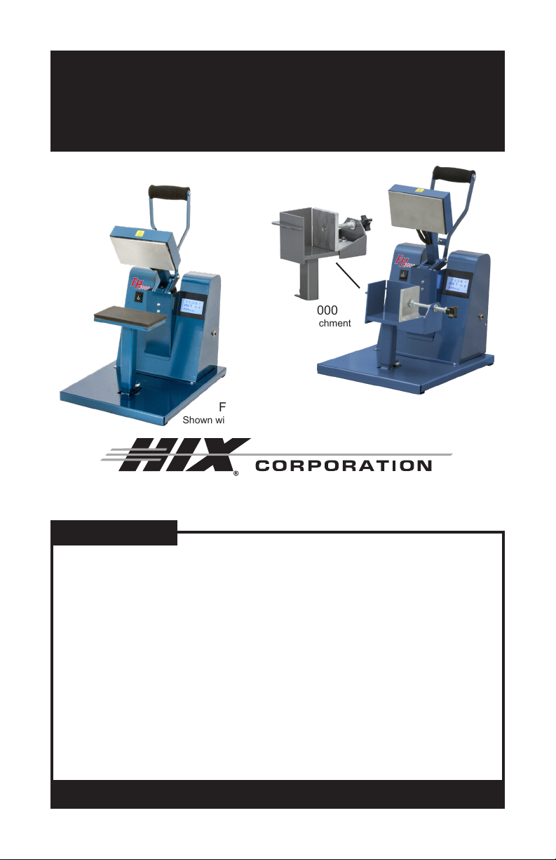
FH-3000
Combo Flat/Cube Heat Transfer Machine
OWNER’S MANUAL
CONTENTS
BEFORE warranty repair you MUST get Prior Authorization:
For Customer Service, Call 1-800-835-0606
or Visit www.hixcorp.com
FH-3000
Shown with Flat Attachment FH-3000
Shown with Cube Attachment
FH-3000
Cube Attachment

2
RECEIVING & INSTALLATION
SHIPPING OR RETURNS
NOTE: Save all of your shipping/packing materials.
******DO NOT RISK COSTLY SHIPPING DAMAGE!******
******SHIP ONLY IN ORIGINAL BOX.******
1. Fasten machine to plywood shipping base with bolts provided.
2. Tie or tape handle securely to base.
3. 3. Place in original box, and put side liner and top liner in place. Fold
in aps and seal the box. (Additional bottom boards, box and liners
may be obtained from your supplier for a nominal cost.)
UNPACKING
Remember to save all packing materials - including box, liner and
board. You may need these for shipping your machine or if a repair is
necessary in the future.
INSPECTION
Inspect your machine for hidden shipping damage. Contact the delivery
company immediately, should you nd damage.
INSTALLATION
1. Remove plywood shipping base bolt and screw on feet or afx self-
adhesive rubber feet provided.
CAUTION: Handle must be tied to base before moving or shipping.
ATTENTION: Immobiliser la poignée avant de trasporter.
2. Carefully cut tape/wrap holding machine closed.
3. Plug the machine into the correct grounded electrical outlet.
WARNING: When using an extension cord, use 12 or 14 ga.-3 conductor.
Maximum length, 25’ (7.762 m).
ATTENTION: Utiliser des ralonges d’au moins 12 à 14 ga - 3 phases;
longueur maximale de 7.7 mètres.

3
RECEIVING & INSTALLATION
CHANGING PLATEN ATTACHEMENTS
1. To switch the different attachments, just lift the attachment off, replace
with other attachment. Adjust screw to change height.
2. Load paper cube tight against the back and non moving side. Tighten
adjustment knob.
Adjustment Rod

4
OPERATION
1. Turn on the machine by pushing the on/off switch.
Startup/Splash screen is displayed as the controller boots up.
NOTE: The current program number and the software revision of the control-
ler are displayed at startup. (The default settings are program number
P 7 for °F, P 8 for °C and software revision RV 1.0)
After boot up, the home screen is displayed showing the current heat platen
temperature and set cycle time. The heat indicating lamp is represented
by the snowake in the upper left corner of the display. The heat indicating
lamp will display anytime the heating element is heating and will cycle on
and off after the set temperature is reached to maintain set temperature.
MACHINE PRESET
BUTTONS
ACCESS
SETTINGS MENU
TEMPERATURE
READOUT/SETTING
HEAT INDICATING
LAMP
TEMPERATURE
MODE
TIME
READOUT/SETTING TIME SCALE
PRESSURE READOUT
HOME MENU SCREEN
Startup/Splash Screen
5
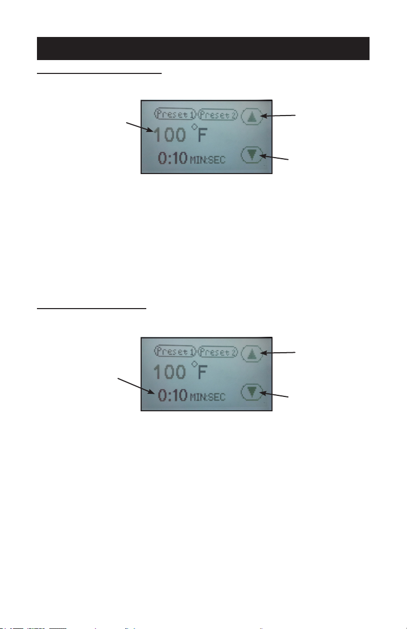
SETTING TEMPERATURE & TIME
ADJUST TEMPERATURE:
1. Touch the temperature readout on the display. “UP” ▲ and “DOWN” ▼
arrows will appear on the right side of the display and the temperature
value will start ashing and to indicate it is in set mode.
2. Press the “UP” ▲ or “DOWN” ▼ arrow to change the temperature
value. Holding down on an arrow will change the temperature in 1 de-
gree increments for 10 values; then change to 10 degrees incremental
changes.
3. Once the desired temperature value is set, either press the temperature
value to lock the set temperature or simply wait for 2 seconds and it
will lock in the new value automatically.
ADJUST CYCLE TIME:
1. Touch the time readout on the display. “UP” ▲ and “DOWN” ▼ arrows
will appear on the right side of the display and the cycle time value will
start ashing and to indicate it is in set mode.
2. Press the “UP” ▲ or “DOWN” ▼ arrow to change the cycle time value.
Holding down on an arrow will change the time in 1 second increments
for 5 values; then change to 10 seconds incremental changes.
3. Once the desired cycle time value is set, either press the time readout
to lock the cycle time or simply wait for 2 seconds and it will lock in the
new value automatically.
TIME ADJUSTMENT SCREEN
UP ARROW
DOWN ARROW
TIME
READOUT/SETTING
TEMPERATURE ADJUSTMENT SCREEN
TEMPERATURE
READOUT/SETTING
UP ARROW
DOWN ARROW

6
PREFERENCE SETTINGS
SETTINGS:
1. Press the “?” on the upper right corner of the display on the Home
Menu Screen to access the settings menu.
2. Press the settings sub menu title to be adjusted.
SHUTDOWN TIMEOUT
The shutdown feature shuts off the heat to the press after a period of in-
activity.
NOTE: The factory default is set at 3.0 hours.
1. From the settings menu press the “Shutdown Timeout” sub menu
title.
2. Press the “UP” ▲ and/or “DOWN” ▼ arrows to set the desired shut-
down time.
NOTE: Shutdown time adjusts in 1/2 hour intervals. Press the “Down” ▼
button until “Disable” is displayed will deactivate this setting.
3. Press “Save” to save the setting.
4. Press “Back” to return to the previous screen.
NOTE: After the shutdown time has elapsed with the press idle, the heating
element will stop cycling to maintain the set temperature and the
home screen will display “SHUTDOWN.” Touching the display or
closing the press will take the machine out of shutdown mode.
SETTINGS MENU SCREEN
RETURN TO
PREVIOUS
SCREEN
ADJUST SHUTDOWN TIMEOUT
SETTING
SET QUANTITY OF PRESETS
DISPLAYED
VIEW/RESET CYCLE COUNT
SET TEMPERATURE SCALE
PREFERENCE
SET TIME SCALE PREFERENCE
SHUTDOWN TIMEOUT ADJUSTMENT SCREEN
UP ARROW
DOWN ARROW
SHUTDOWN TIMEOUT
SETTING
SAVE SETTINGS RETURN TO PREVIOUS SCREEN

7
MACHINE PRESETS
PRESET QUANTITY
Temperature presets can be stored in the memory for different trans-
fer settings. By default two presets are displayed. This setting can be
adjusted to display four presets.
1. From the settings menu press the “Preset Quantity” sub menu title.
2. Press the number of presets to be displayed on the home screen, either
“Two Presets” or “Four Presets.”
3. Press “Save” to save the setting.
4. Press “Back” to return to the previous screen.
NOTE: The “Toggle Two Presets” option will allow the operator to save two
different times in each preset (e.g. 2 seconds in Preset 1 and 8
seconds in Preset 2). Each time the handle is closed and the timer
times out then the controller will automatically “toggle” to the other
preset. This will allow the operator to set a short “pre-press” time.
The “No Presets” option, if selected, will remove the option for any
preset buttons to appear on the Home Menu Screen.
TWO PRESET DISPLAY
ON HOME MENU SCREEN
FOUR PRESET DISPLAY
ON HOME MENU SCREEN
TWO PRESETS
DISPLAYED
FOUR PRESETS
DISPLAYED
SAVE SETTINGS RETURN TO PREVIOUS SCREEN
PRESET QUANTITY DISPLAYED PREFERENCE SCREEN
NO PRESETS
DISPLAYED
TOGGLE BETWEEN
PRESETS

8
MACHINE PRESETS
STORING PRESETS:
NOTE: The factory default settings for all presets is set to 200°F and 10
seconds.
1. Set the desired temperature and/or cycle time using the temperature
and time adjustment instructions in this document.
2. Press and hold the desired preset location for two seconds. The con-
troller will beep and the preset location button will display in reverse
indicating the preset is stored in memory.
NOTE: Always refer to specic transfer recommendations for temperature,
time and pressure as instructed by the transfer manufacturer.
RECALLING PRESETS:
1. Press and release for approximately 1/2 second the preset button to
recall. The controller will beep and the preset location button will display
in reverse indicating the preset has been changed.
NOTE: The new set values will display for 1 second before the controller
starts adjusting the temperature or time to match the new set-
point.
PRESET 1 SELECTED
(two preset setting shown)
PRESET 2 SELECTED
(two preset setting shown)
PRESET
LOCATIONS
(press 1/2 second
to recall)
PRESET
LOCATIONS
TEMPERATURE
SETTING
TIME
SETTING
HOME MENU SCREEN

9
CYCLE COUNT
CYCLE COUNT
The cycle count feature counts the number of cycles that the machine
has undergone. A cycle is counted every time the countdown timer is
activated by closing the press.
NOTE: The cycle count will maintain the total count even if the power has
been turned off.
TO RESET THE COUNTER:
1. From the settings menu press the “Cycle Count” sub menu title.
2. Press “Reset.”
3. Press “Back” to return to the previous screen.
CYCLE COUNT/CYCLE COUNT RESET SCREEN
CYCLE COUNT
RESET TO ZERO RETURN TO PREVIOUS SCREEN

10
TEMPERATURE & TIME MODES
TEMPERATURE MODE
Temperature Mode controls which temperature scale is displayed on
the controller home screen.
F= Fahrenheit C= Celsius
TO CHANGE THE SCALE:
1. From the settings menu press the “Temperature Mode” sub menu
title.
2. Press the “UP” ▲ or “DOWN” ▼ arrows to select the preferred tem-
perature scale.
3. Press “Save” to save the setting.
4. Press “Back” to return to the previous screen.
TIME SCALE
The time scale setting adjusts how the time is displayed on the home
screen. There are three Time Scale display options available in the
Time Scale menu:
• MIN:SEC (Factory Default)
• SEC (Seconds)
• 1/10 SEC (1/10 Second Resolution)
TO CHANGE THE SCALE:
1. From the settings menu press the “Time Scale” sub menu title.
2. Press the “UP” ▲ and/or “DOWN” ▼ arrows to select the preferred
time scale.
3. Press “Save” to save the setting.
4. Press “Back” to return to the previous screen.
TEMPERATURE MODE PREFERENCE SCREEN
TEMPERATURE SCALE
PREFERENCE
SAVE SETTINGS RETURN TO PREVIOUS SCREEN
UP ARROW
DOWN ARROW
TIME MODE PREFERENCE SCREEN
TIME SCALE
PREFERENCE
SAVE SETTINGS RETURN TO PREVIOUS SCREEN
UP ARROW
DOWN ARROW

11
PLATEN PRESSURE
1. There is a pressure control knob located on the front stem, holding the
lower platen. Set so that the heat head will lock down rmly, with your
substrate in place.
2. Pressure is reduced by turning knob (with machine open) counter-
clockwise and increased by turning it clockwise.
NOTE: Adjustments may be required from one garment to another and will
vary to achieve the desired result.
WARNING: Excessive pressure can cause structural damage, voiding
the machine warranty!
ATTENTION: Pression excessive peut endommager la machine et
annuler la garanti.

12
TRANSFER APPLICATION
When you fail to make a successful transfer you can wonder, “Is it
the machine’s fault, or the transfer, wrong settings or what”?
FIRST, THE BASICS:
1. Be sure to set the heat transfer machine to the transfer manufacturer’s
recommended Temperature, Time and Pressure settings. If you don’t
have these specications, contact your transfer supplier for this infor-
mation and any other special application instructions as many of the
new “High Tech” transfers require signicantly different settings and/or
application techniques than those from years past.
2. When you start up your press for the rst time each day, preheat the
pad for a minute. If the press has sat for 3-5 minutes without use, be
sure to “preheat” the pad for 10-15 seconds before loading the shirt or
making the rst transfer.
3. After the shirt is positioned and centered on the preheated pad, “pre-
press” the shirt for 3 seconds to take the wrinkles out and more impor-
tantly, release any excess moisture out of the T-shirt fabric which can
reduce the chance of a successful transfer.
4. With all of the above recommendations, try making a transfer.
5. If successful, great! You are on your way to making some serious
money with your transfer machine!
6. If you have an area that isn’t transferring completely or as you would
like it to, follow these steps to determine the problem.
• Try increasing the pressure on the machine by 10-20%
• Recheck your temperature required and the press readout. You may
want to increase the temperature 10 degrees.
• Try increasing the application time by 2-4 seconds
• If after trying these things there is still a “specic” area (say over in
one corner of the transfer) that isn’t coming out as you would like
it to, then try the same type transfer on a scrap shirt but rotate the
transfer 180 degrees (changing the failure location) If after doing
this the problem area is in the same physical location on the ma-
chine, then you probably have a problem with the pad or possibly a
warped platen if the machine has ever overheated severely. On the
other hand if the transfer failed in the same area on the transfer (af-
ter changing the location of where the problem had previously been
occurring), then you most likely have a problem with the transfer or
it’s application settings (Temperature, Time or Pressure) and you
should contact your transfer supplier to discuss the problem.
Following these basic guidelines can help you be more successful with
each and every transfer!

13
REPAIRS/ADJUSTMENTS
RELAY BYPASS
WARNING: Before making repairs, be sure ON/OFF switch is OFF
and machine is unplugged!
ATTENTION: Eteindre la machine avant de faire des réparations.
1. Remove the back cover of the machine.
WARNING: To prevent posible electrical shock, unplug the machine
before removing cover to service.
ATTENTION:And’éviter des choquesélectriques, éteindre lama-
chine avant d’ouvir.
2. Remove wire #26 from terminal #2 on relay.
3. Loosen terminal #1 on relay and replace wire #26 along with wire #12
under terminal #1.
4. Tighten the connection.
5. Plug machine in and turn the power switch on.
NOTE: Replace the relay if the machine starts heating. This is a test only.
Do not operate machine with relay bypassed.
TOGGLE ADJUSTMENT
NOTE: If machine is hard to open, follow step 1. If machine will not stay
locked down, follow step 2.
1. Loosen the toggle bolt lock nut. Turn toggle bolt in 1/4 increments
clockwise as viewed from top. Lock handle down. Repeat until ma-
chine operates comfortably and locks down securely. Tighten toggle
lock nut and check operation. If turned too far, machine will not stay
locked when closed.
2. If toggle bolt does not contact main arm and excessive pressure is
required on handle, reduce pressure by turning pressure knob coun-
terclockwise. Repeat. (See page 3, “Operations”). If contact is made
but handle won’t lock down, turn toggle bolt 1/4 turn (counterclockwise
as viewed from the top). Repeat until handle locks down comfortably.
Tighten toggle lock nut and check for proper operation.
Toggle Bolt Lock Nut

14
MICRO SWITCH ADJUSTMENT
If countdown timer will not activate.
WARNING: Before making repairs, turn temperature control knob to
“OFF” and unplug machine!
1. Remove rear cover.
2. Using a screwdriver and a small wrench loosen micro switch mounting
screws
3. Adjust switch so it “clicks” only when machine is locked down.
4. Tighten mounting screws, replace rear cover and check operation.
LUBRICATION
Your press requires lubrication every 6 months. Using 3-in-1 oil (available
from your hardware store), add one to two drops of oil at the joints of
all moving parts.
CLEANING HEAT PLATEN
You may clean the heat platen with steel wool, scrubbing aluminum
sponge, or ne wire brush.
REPAIRS/ADJUSTMENTS
MAINTENANCE
15
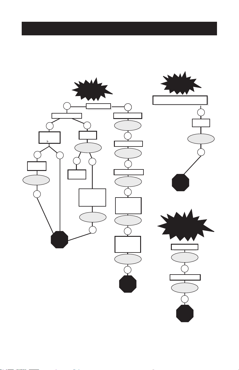
TROUBLESHOOTING
*Customer Service Tech Sheets are available for this step. Visit
www.hixcorp.com to print or call 620-231-8568 and we will send
you one. Parts ordering is available on-line.
Machine
overheats
Call
Technical
Service
NO
Does heat light remain on constantly
when overheating?
NO
Call
Technical
Service
NO
Check large tan
wires crimped to
back of heat casting.
Repair if needed.
Problem solved?
YES
Little or
no heat
Is power light on?
YES
Try another outlet.
NONO
Call
Technical
Service
Problem solved?
NO
Reset Circuit Breaker
Problem solved?
NO
Problem solved?
NO
Check power flow
with VOM meter
Repair if needed.
NO
Replace on\off switch.
NO
Problem solved?
Remove rear cover
and check for loose
or broken wires
Repair if needed.
Does the digital
display show
" C"?
Replace
thermocouple.
∗
∗
∗
Problem solved?
Is heat light on?
NO YES
YES
Problem solved?
NO
Bypass
relay.
Replace
relay.
∗
Replace
Relay
Problem solved?
NO
∗
NO
Problem solved?
Machine
won't stay
closed.
Call
Technical
Service
NO
NO
Problem solved?
Problem solved?
Adjust pressure.
Adjust toggle bolt.

16
(Effective 3/1/2020)
HIX will automatically register the equipment on the date it was shipped to you or your distributor. If the
equipment was not purchased directly from HIX, but through a distributor (either domestic or foreign), please
keep a copy of their sales invoice showing the serial number and date it was sold/shipped to you with this war-
ranty. In this case, we will use the distributor’s invoice date as the beginning warranty date. STAPLE A COPY
OF YOUR PROOF OF PURCHASE TO THIS WARRANTY and keep in a safe place to provide verication of
your warranty should a problem occur. Thank you.
Please ll in the following information and attach a copy of your receipt for your records.
Date Purchased: From:
Model #: Serial #:
This warranty applies to equipment manufactured by the HIX Corporation (HIX), Pittsburg, Kansas, U.S.A.
HIX warrants to the original purchaser, its Ovens and Dryers, Heat Transfer Machines, Textile Printers, Spot
Heaters, and Exposure Units against defects in workmanship and material, except for wear and tear for a
period of “One Year” from the date of purchase. HIX warrants Accessories for a period of 90 days from the
date of purchase. doughXpress products are covered under separate warranty.
In the event of a defect, HIX, at its option, will repair, replace or substitute the defective item at no cost
during this warranty period subject to the limitations of insurance and shipping costs stated below (excludes
labor).
In the case of heat transfer presses (except the Hobby Lite and Large Format presses), HIX warrants the
heat casting for the “Life” of the machine for the original purchaser. If a part becomes obsolete at the time
for repair, and/or cannot be reasonably substituted for, HIX will credit, at half the then current list price or last
recorded price, only that part toward a new machine or any product HIX offers. This credit offer shall be the
sole responsibility of the HIX Corporation in the event of an obsolete part.
This warranty does not cover belts, rail tape, pads, mug wraps, canvas, rubber blankets, bulbs, glass.
Warranty does not cover damages due to accident, misuse/abuse, alterations or damage due to neglect, ship-
ping or lack of proper lubrication or maintenance. HIX shall not be responsible for repairs or alterations made
by any person without the prior written authorization by HIX. This warranty is the sole and exclusive warranty
of HIX and no person, agent, distributor, or dealer of HIX is authorized to change, amend or modify the terms
set forth herein, in whole or in part.
In the case of a problem with the equipment identied herein, HIX Corporation should be contacted during
regular business hours to discuss the problem and verify an existing warranty. HIX personnel will assist the
customer to correct any problems which can be corrected through operation or maintenance instructions,
simple mechanical adjustments, or replacement of parts. In the event the problem cannot be corrected by
phone, and upon the issuance of a return authorization by HIX, the equipment shall be returned to HIX or an
authorized service representative. All insurance, packaging and shipment/freight costs are solely the respon-
sibility of the customer, and not that of HIX, and HIX shall not be responsible for improper packaging, handling
or damage in transit. Contact HIX customer service for complete return authorization information. Correct
shipping boxes are available from HIX.
This expressed warranty is given in lieu of any and all other warranties, whether expressed or implied,
including but not limited to those of merchantability and tness for a particular purpose, and constitutes the
only warranty made by HIX Corporation.
In no event shall HIX’s liability for breach of warranty extend beyond the obligation to repair or replace the
nonconforming goods. HIX shall not be liable for any other damages, either incidental or consequential, or the
action as brought in contract, negligence or otherwise.
This warranty gives you specic legal rights and you may also have other rights which vary from state to
state.
WARRANTY
1201 E. 27th Terrace • Pittsburg, KS 66762 • U.S.A.
Web site: www.hixcorp.com • Phone: (800) 835-0606 • Fax: 620-231-1598
©2020 HIX Corp.
Design and Manufacturers of Graphic Imaging, Commercial Food, Industrial and Custom Drying Equipment
Table of contents
Other Hix Industrial Equipment manuals


Popular Industrial Equipment manuals by other brands


StorCase Technology
StorCase Technology Data Silo DS321 user manual

Chamberlain
Chamberlain Clopay HPH1 installation manual

Apeks
Apeks TRANSFORMER 2000PSI installation manual

Eaton
Eaton P3-63/SE3 Series Instruction leaflet

Parker
Parker OLAER HY10-4005-UM/UK Product information

OMCA
OMCA SMJ Use and maintenance manual