Hoffman INNOVATEIT User manual

Fully Integrated, High-Efficiency R.O. Spot-Free Rinse System
For Further Assistance Please Contact
innovateIT Car Wash Equipment LLC
518-741-4200 option 2
Instruction Manual
REV2.00
Updated 11/2/2023
INNOVATEIT
HOFFMAN
REVERSE OSMOSIS

2 |Section
Table of Contents
1. Introduction...................................................................................................................................................................................................................4
1.1 Warranty...............................................................................................................................................................................................................4
1.2 Safety Information..................................................................................................................................................................................4
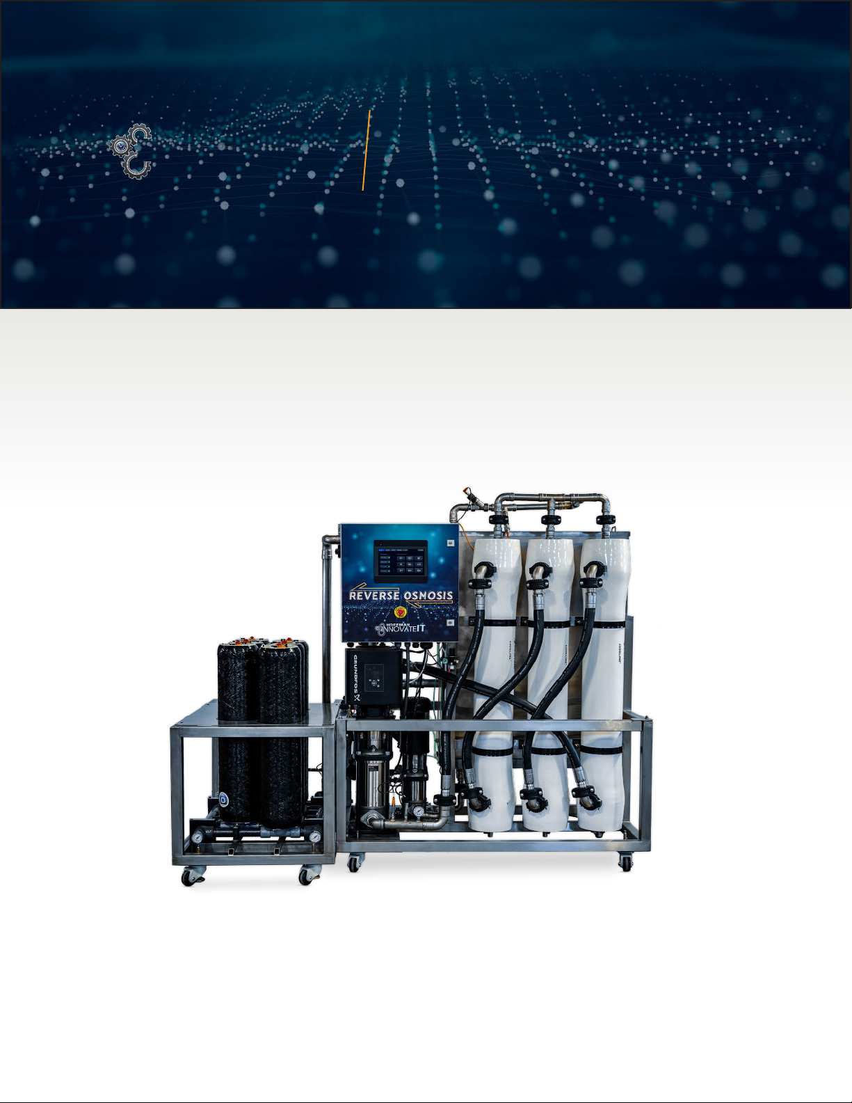
2. System Overview...................................................................................................................................................................................................5
2.1 Principles of Operations.................................................................................................................................................................7
2.2 System Operation...................................................................................................................................................................................7
2.2.1 Pump Inlet Pressure Switch (PS1)....................................................................................................................7
2.2.2 RO Pump Pressure Switch (PS2)........................................................................................................................8
2.2.3 RO Product Flow Sensor (ROFLO)...................................................................................................................8
2.2.4 Tank Level Sensor..................................................................................................................................................................8
2.2.5 Recirculation Flow Switch...........................................................................................................................................8
2.2.6 Re-Pressurization Pump Flow Switch........................................................................................................9
2.3 System Functions ....................................................................................................................................................................................9
2.3.1 Stop Mode.........................................................................................................................................................................................9
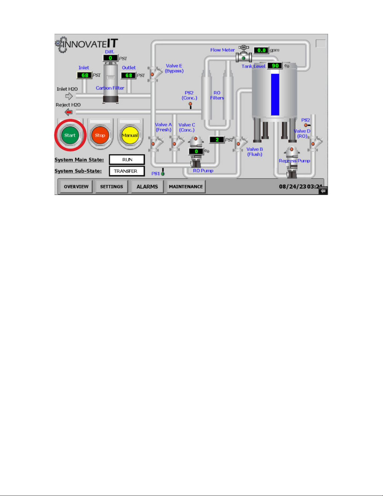
2.3.2 Start Mode.........................................................................................................................................................................................9
2.4 Tunnel Signal Command for RO Water Delivery to Tunnel.....................................................10
2.5 RO Storage Tank...................................................................................................................................................................................10
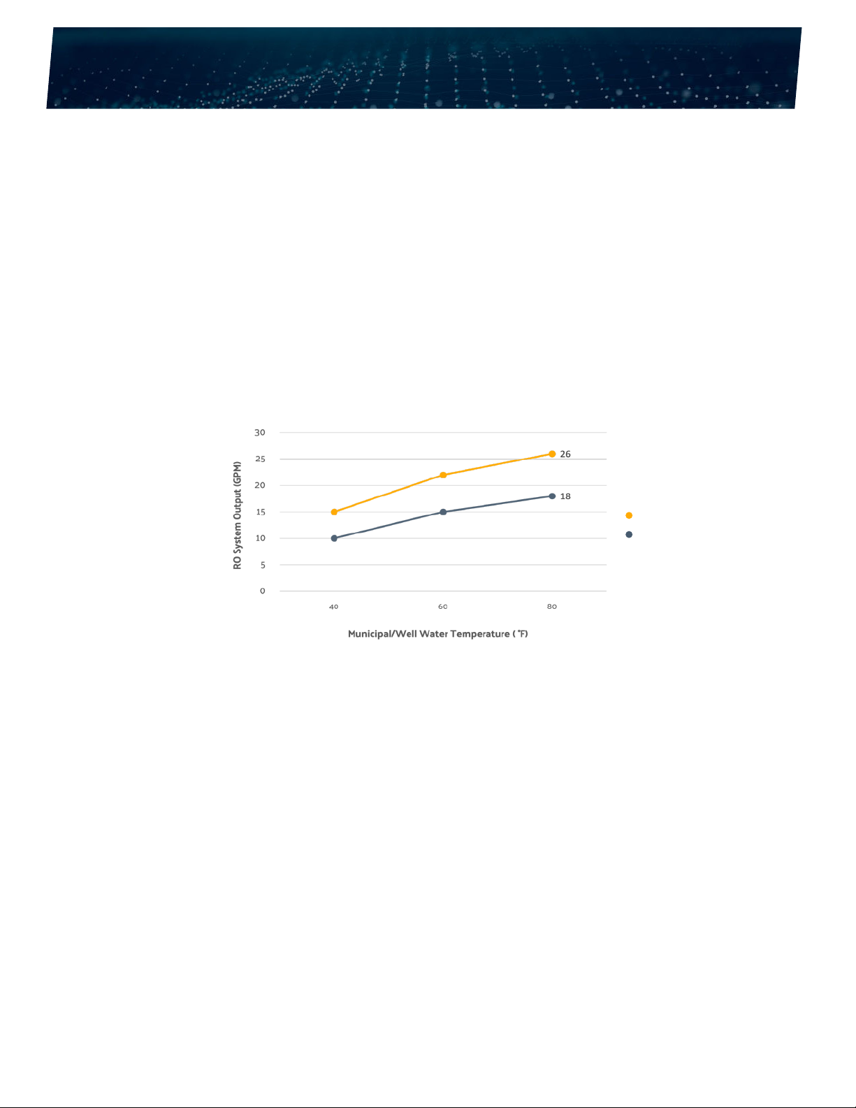
2.6 System Performance ........................................................................................................................................................................11
3. Installation Requirements......................................................................................................................................................................13
3.1 Pre-Treatment Solutions.............................................................................................................................................................13
3.1.1 Carbon Block for Chlorine and Chloramine Removal.......................................................13
3.1.2 Additional Feed Water Pre-Treatment...................................................................................................14
3.1.3 System Requirements...................................................................................................................................................14
3.2 Installation Preparation................................................................................................................................................................14
3.2.1 Water Supply.............................................................................................................................................................................15
3.2.2 Floor Drain.....................................................................................................................................................................................15
3.2.3 Compressed Air Supply...............................................................................................................................................15
3.2.4 Unit Placement.......................................................................................................................................................................15
3.4 ReverseOsmosisSystemIdenti cation...............................................................................................................16
4. Installation....................................................................................................................................................................................................................17
4.1 System Installation.............................................................................................................................................................................17
4.1.1 RO Membrane Installation......................................................................................................................................19
4.1.2 Electrical Installation......................................................................................................................................................20
5. System Startup......................................................................................................................................................................................................23
6. Maintenance.............................................................................................................................................................................................................28

Section | 3
6.1 Replacement Parts............................................................................................................................................................................28
6.1.1 Catalytic Carbon Block Assembly.................................................................................................................28
6.1.2 Carbon Filter...............................................................................................................................................................................28
6.1.3 RO Mebrane System (Membranes and O-Ring Seals in Housing) .................28
6.1.4 Pressure Switches..............................................................................................................................................................29
6.1.5 ASCO 8290 Air Valves (A-D)..................................................................................................................................29
6.1.6 Air Pilot Air Valve.................................................................................................................................................................29
6.1.7 Pumps.................................................................................................................................................................................................29
6.1.8 Electrical/Controller Hardware........................................................................................................................29
6.1.9 Flow Switch.................................................................................................................................................................................29
6.2 Maintence Schedule ........................................................................................................................................................................29
7 Troubleshooting..................................................................................................................................................................................................32
7.1 HMI Fault Codes.....................................................................................................................................................................................34
8 Glossary of Terms..............................................................................................................................................................................................36
Appendix1-ROSystemIdenti cation................................................................................................................................38
Appendix 2 - Electrical Schematic..............................................................................................................................................42
Appendix 3 - Spare Parts.........................................................................................................................................................................48

Section Header
4 |Introduction
Introduction
1. Introduction
The manufacturer innovateIT Car Wash Equipment LLC is committed to the continuous improvement of its equipment
construction quality and the safe operation of its equipment.
1.1 Warranty
This manual covers the installation, intended use, and maintenance of the Reverse Osmosis (RO) Spot-Free Rinse System.
Misuse or improper operation of this device will void the manufacturer’s warranty.
A 1-year limited warranty from the shipping date covers this product. This warranty shall be void and of no effect if:
• Any installation defect that was apparent or ascertainable at the time of installation was completed but was not
promptly reported to innovateIT Car Wash Equipment LLC.
• Damage occurs due to the customer’s failure to observe any instructions from innovateIT Car Wash Equipment or an
authorized distributor and/or requirements of the manufacturer with respect to the product.
• The breach results from misuse of the equipment as outlined in the instruction manual.
When purchasing through a distributor, please ask about their warranty coverage on the unit.
1.2 Safety Information
CAUTION!
FAILURE TO FOLLOW INSTALLATION AND OPERATING INSTRUCTIONS MAY RESULT IN DAMAGE TO EQUIPMENT OR
PERSONAL INJURY.
The instructions in this manual provide you with the information necessary to install and operate the R.O. System. Before
starting installation, the instruction manual should be carefully read and understood. This relates to all Reverse Osmosis
Spot-Free Rinse System documents from innovateIT Car Wash Equipment.
The basic pre-requisite for safe working is compliance with all the safety and handling instructions stated in this manual.
Furthermore, follow all local accident, hazard prevention regulations or general safety regulations when installing and operat-
ing the R.O. System.
The equipment’s operation, maintenance, and troubleshooting must only be carried out by trained personnel. Personnel be
abletointerpretawiringdiagram,useamultimetertoreadACandDC,andapplyLockOutTagOutsafetyproceduresspeci c
to the equipment.
Eye protection should be worn at all times when operating the RO. System, as the unit includes high pressure water lines and
membranehousingswhichmayleakif ttingsloosenovertime.
Electrical installation must adhere to local codes and the National Electrical Code, ANSI/NFPA 70 for electrical wiring. To avoid
electrical shock hazards, do not operate this device when controller enclosures are open and energized. Electrical power must
be shut off and a lock-out procedure utilized to ensure all electrical power is disabled before performing maintenance to any

Introduction | 5
portion of the system.
Plumbing installation must adhere to a local code and Uniform Plumbing Code (UPC), and plumbing connections and drains
must adhere to local standards and facility codes.
• Do not remove any Caution, Warning, or any other descriptive labels from the RO system.
• Donotoperatethisdeviceinanexplosiveenvironmentorinthepresenceof ammablematerials.
• Movement or vibrations during shipment may cause connections to loosen. Check all connections before
starting up a unit.
• Do not operate this unit in an environment where water temperatures may be below 40°F or above 80° F.
• This equipment is intended for installation in ordinary locations, by the National Electrical Code, ANSI/NFPA 70,
where the ambient temperature does not exceed 104°F maximum.
innovateIT Car Wash Equipment LLC does not accept liability for accidents or damages due to negligence or disregard for
the instructions in this manual. Also, the Company does not accept liability for damages due to improper use of the equipment.
This instruction manual should always be kept in a safe and easily accessible place near the equipment’s site of installation
and operation, and be available for the operator at the user site at any time.
If the manual is damaged, lost, or misplaced, you should mmediately request a new copy from innovateIT Car Wash
Equipment LLC.

System Overview
6 |System Overview
2. System Overview
innovateITCarWashEquipmentLLChasdevelopedahigh-ef ciencyreverseosmosissystemtoprovidespot-freerinse
service for express car wash applications.
The system uses “Flow on Demand” control algorithm to adjust pump pressure based on number of cars being washed, opera-
tor demand, and condition of the membranes.
The VFD pump allows the system to respond to the car wash demand for RO water and is sized to generate RO needed to
match the demand throughout the day. This approach allows the use of a reduced-size RO storage tank which is fully integrat-
ed into the RO stainless steel stand.
Inaddition,theVFDpumpallowstheunittoproducefull ow(10GPM–StandardFlow,15GPM–HighFlow)downto40Ffeed
watertemperaturetoensureconsistent owforthewasheveninextremelyfrigidwinterclimates.
RO usage is monitored and the RO production rate is automatically adjusted to meet the demand (number of cars in the tun-
nel)toimprovetheenergyef ciencyofthesystemandeliminatetheon/offcyclingtypicalofexistingROsystems.
In addition, the integrated system eliminates the cost of buying and installing large buffer storage tanks needed to meet the
high-volume tunnel demand at busy washes.
This R.O. System has been engineered to allow years of trouble-free operation and low life cycle costs for the operator. The
systemutilizescommercial(highef ciency)ROmembranesthatoperatefrom70to200psipumppressures.Allthecompo-
nents(chlorine lter,pumps,membrane,etc.)havebeenselectedtoimprovethesystem’sreliability,minimizeenergyuse,and
reduce required maintenance.
AlargetouchscreenHumanMachineInterface(HMI)providesanintuitivescreendisplayfortheoperatortomonitorand ne-
tune system performance according to the wash site.
The unit includes the RO storage tank but requires a separate tank for the rejected water. RO reject water is recommended for
use for other wash processes which include wheel blasters, underbody spray, and various rinse processes.
g. 2 - 1 - Feed water temperature vs. RO output
High Flow
Standard Flow

System Overview | 7
2.1 Principles of Operation
NOTE: Most car washes operate with varying feed water temperatures over the course of the year. This unit is designed to
ensure that the unit produces adequate RO for rinsing cars across a wide range of feed water temperatures and levels of
dissolved solids.
The system is designed to automatically generate the required RO for the demand of the tunnel (up to 24,480 GPD with the
Standard Flow system or 37,440 GPD with the High Flow system.
The unit uses the Grundfos VFD Pump along with a PLC controller to match the RO production to the RO usage. This ap-
proachproduceshighqualitywaterwithmaximumoperatingef ciency.
Thetanklevelsensor(pressuresensor)isusedtogeneratetherequestforROproduction owratewhichvariesbasedupon
theROstoragetanklevel.Thisfeatureallowsthesystemtoincrease owasthetankleveldrops.Whenmatchedtoproperly
sized nozzles in the tunnel, the unit is designed for up to 200 cars per hour continuously.
Thevariable owapproachbasedontanklevelallowstheuseofasmallerROstoragetankswhichintegratedirectlytotheRO
system. The result of this feature allows the pump to operate at lower pressures for longer periods, increasing membrane life
andreducingpumpcycling.Thisavoidsshortcyclingthepumpandallowsunittorunef cientlyevenduringperiodsoflowor
intermittent carwash tunnel volume.
An electrical control box is installed on the unit which includes the PLC, HMI, and mechanical disconnects from the main pow-
er supply, to convert the 480VAC three-phase power to 24 VDC to power the HMI, PLC, and air solenoids and water quality TDS
sensor (24Volt).
The control box also includes a motor starter for the re-pressurization pump which uses RO water from the storage tank and
deliversRO owtothetunnel.There-pressurizationpumpisturnedonbasedonanROrequestsignalfromthetunnelcon-
troller and does not integrate into the RO production pump controller.
A owswitchandanairoperatedsolenoidvalvehavebeenaddedtothere-pressurizationpumpoutputtoprotectthepump
fromadryrunningcondition.Thisfeaturewillturnoffthere-pressurizationpumpandregisterafaultifthe owswitchfailsto
close.
The electrical inputs and outputs (I/O) has been selected to minimize the number of sensing devices while providing the abili-
ty to diagnose failure of the equipment.
2.2 System Operation
The following input and output signals are used to provide the controller information to operate and troubleshoot the system.
These sensors are shown on the system schematic (Appendix 2).
2.2.1 Pump Inlet Pressure Switch - PS1
• 0-5 psi adjustable pressure switch which is used to detect an issue with the water supply. The switch is normally
open and if this switch fails to close after start-up, it will turn off the RO pump and register a system fault. A PS1 fault
will shut down the RO Production Pump and log a fault in the data log.

8 |System Overview
2.2.2 RO Pump Pressure Sensor - PS2
• This pressure sensor is used to protect the system from operating over the setpoint pressure.
• The system can produce 10 GPM (Standard Flow) or 15 GPM (High Flow) of RO below 200 psi at a water temperature
above 40F.
• This pressure set point is to allow the use of membranes that might be lower-pressure or cold-water membranes.
• This situation may occur as the membranes reach the end of life or if feed water drops below 40 F.
2.2.3 RO Product Flow Sensor - ROFLO
• This sensor provides the feedback signal to the pump controller to adjust RO Pump speed and pressure to achieve
thedesiredRO owrate.Theprogrammed owrateisadjustableonthePLCsettingsscreen.
• This sensor provides a 4-20 mA signal to the controller and the calibration is set in the controller software. This
allowstheoperatortoadjusttherequested owbasedonthetanklevel.Asthetankleveldecreases,the owisset
toincrease.ThisapproachallowstheunittogenerateROatthelowestenergycosttomeetthe owrequiredbythe
tunnel.
• ‘ROProduction’turnsonwhenthetankleveldropsto75%and llsitbackto95%.
• Verify the RO pump turns on when the tank level drops to 75% tank level.
• Once the re-pressurization pump is commanded off, the unit will keep running continuously until the level reaches
100%. The system will wait 15min then initiate a RO MEMBRANE FLUSH CYCLE before shutting down.
• Duringthe ushcycle,theROpumpcirculatesafewgallonsofROwatertothefeedsideofthemembranes.
RO water pulls deposits from the surface of the membranes. The ush water (RO water) remains in the dirty
(concentrate) side of the membranes until the next production cycle.
• Using this method, the feed (concentrate side) of the membranes will always be cleaning the membranes between
the RO production cycles.
Thetankisdividedintothreesectorswhichallow exibilityinset-up.Theobjectiveistoallowtheunittoadjust owbasedon
tanklevelwithlower owratesasthetankisnearing100%fullandhigher owratesasthetankapproachesempty.
The ‘RO Production Turn On’ level is adjustable and will normally be set in the 60% range. In the screen shot above the oper-
ator has set this number to 80%. Based on the settings above the unit will ramp from 0 GPM to 8 GPM when the tank reaches
80% full condition.
2.2.4 Tank Level Sensor
• The tank sensor is a low-pressure sensor that measures the static water head pressure based on the depth of water
in the tank.
• The0-5psisensorisscaledtoa4-20mAsignal.Thissignalisusedtorequest owratebasedonthetanklevel.This
signalisaninputtothePLCwhichisusedtomodifythe owrequestbasedonthetanklevel.
2.2.5 Recirculation Flow Switch
• Therecirculation owswitchveri esthattherecirculationloop ow(thecombined owoftherecirculation owand
reject ow)isoperatingatmorethan12GPMof owduringoperation.
• Thisswitchprotectsthemembranesfromfouling,verifyingthatValveCisopenandtherecirculationandreject ow
ori cesarenotblockedduringROproduction.Ifthereject owori ceortherecirculationori cebecomesblocked
it would increase RO recovery and potentially damage the membranes. The switch will not close if the RO pump
pressure is less than 70 psi.

System Overview | 9
2.2.6 Re-Pressurization Pump Flow Switch
• TheswitchclosesasROpressureatthepump owreaches5GPM.
• Thisswitchveri esthatwhentheRORequestforwaterissentfromthetunnelcontroller,ValveDhasopened,the
deliverypumphasturnedON,andROwateris owingtothetunnel.
• If this switch fails to close it will turn off the re-pressurization pump to protect it from running in a dead-head or dry
running condition. (It is recommended that you have a spare ow switch and cable to allow quick repair if the
switch fails. PN: Flow Switch- RC-FS VK309)
2.3 System Functions
The following diagram shows how the system works and shows the operating steps to operate in START mode.
g 2.3 - 1 - HMI screen in START mode
Each of these functions is designed to ensure a reliable and consistent supply of RO water for the spot-free rinse portion of
the wash.
2.3.1 Stop Mode
The unit will always start up in the STOP mode. In this mode, power is supplied to the RO system, and the 24vac signals are
energized. However, the pumps and solenoid valves are all commanded off. The HMI will show a red dot in the mode button
on the main screen.
2.3.2 Start Mode
PressSTARTontheHMI( g.2.3.2-1)
• The system will go through a short initialization of 5 to 10 seconds.
• START MODE will produce RO water until the tank is full (Set maximum tank %)
• The RO pump will continue to operate until the tank reaches the set tank level %.

10 |System Overview
• Iftheunitisinactivefor15minutes,theunitwillperforma ushcycle.
g 2.3.2 - 1 - START button
Note: IntheeventofeitherlowRO owfromthesystem(duetofailedmembranesorpumpproblems)orifthedemandfrom
thetunnelexceedsthe owfromtheROsystem,thereisamunicipalwaterlinethatusesavalve(E)to lltheROtankifthe
water level drops drop below 25%. This is to protect the re-pressurization pump and ensure rinse water is delivered to the
tunnel.
2.4 Tunnel Signal Command for RO Water Delivery to Tunnel
This signal is controlled directly by the tunnel system controller using a 24 Volt DC relay signal to the R.O. System Controller
and is used to turn on the Re-Pressurization Pump.
This signal switches on and off for each car in the tunnel based on the conveyor speed. The re-pressurization pump is limited
to 180 cycles per hour (maximum continuous cycle rate).
2.5 RO Storage Tank
ThestainlesssteelROstoragetankisintegratedintothestainlesssteelstand.Municipalwater owstoasolenoidoutsidethe
tank to automatically supply municipal water to the tank if there is a failure in the system.
Note: ThesolenoidsupplieswateriftheROpumpormembraneshavereducedRO ow.

System Overview | 11
WARNING!
THE 24V DC SIGNAL MAY BE PRESENT IN THE SYSTEM CONTROLLER EVEN WHEN THE CONTROLLER POWER HAS
BEEN MANUALLY DISCONNECTED FROM THE 3-PHASE POWER SOURCE. YOU MUST TURN OFF THE 24 V
ELECTRICAL SIGNAL (RO REQUEST) FROM THE RO SYSTEM CONTROLLER BEFORE PERFORMING MAINTENANCE OR
REPAIR TO THE SYSTEM CONTROLLER. FAILURE TO DE-ENERGIZE THIS CIRCUIT COULD LEAD TO EQUIPMENT
DAMAGE OR PERSONAL INJURY.
2.6 System Performance
ThestainlesssteelROstoragetankisintegratedintothestainlesssteelstand.Municipalwater owstoasolenoidoutsidethe
tank to automatically supply municipal water to the tank if there is a failure in the system.
RO systems are designed to provide spot-free rinse water to the car wash tunnel and are rated by the volume of RO water
produced per day. Membranes are extremely sensitive to feed water temperature and will typically lose approximately 2% of
owforevery1Fdropinfeedwatertemperatureatconstantpressure.
The innovateIT R.O. System is conservatively rated for consistent performance from 40F to 80F feed water temperatures. The
systemutilizesoversizedmembranesoperatingatconservative uxratingscombinedwithdailyRO ushcyclestoachieve
high-quality water and long membrane life.
Theunitprovides10GPM(StandardFlow)/15GPM(HighFlow).Themaximumcommanded owatlowtanklevelsis18GPM
(StandardFlow)/26GPM(HighFlow)areprogrammed.Thesemax owratingscanonlybeachievedwhenthewatertempera-
ture is 77F or above.
The RO volume (gallons per car) should be set for the coldest expected feed water which eliminates the need to adjust the
owtothetunnelthroughouttheyeartoadjustforchangesinmunicipalwatertemperaturevariation.Thepressurerequired
togeneratefull owwillrangefrom70psi(@80°F)to200psi(@40°F).
The Grundfos VFD pump has been oversized to allow this wide range of temperature capability while using Dupont (formerly
Dow Filmtec) membranes which ensure high quality (low TDS RO water). The VFD pump also allows pumping at the correct
pressureand owtogeneratetheneededRO owtosupportthetunneldemand.
Although the unit has a 7.5 HP pump, most of the time this system will be running at much lower power. The electrical energy
usedtogeneratetheROincreasesastheROmembrane owincreases.
The result of generating RO at the rate required to satisfy the tunnel demand results in reduced energy consumption per gal-
lon of RO produced. The membrane’s performance varies as the feed water temperature changes. This means the RO pump
pressuremustincreasetomaintain owasfeedwatertemperaturedrops.
Overtime,the owandpressuresmayvary.Lower owrateswouldindicatepotentialscalingorfoulingofthemembranes
andhigherRO owsorincreasingROTDSreadingsmayindicateeithermembranedamage(causedbychlorinedamage)ora
membrane O-ring seal leak.
The TDS of the RO water ranges between 0 and 15 PPM with new membranes. New membranes process chemicals in the RO
membrane material, and the initial 60 minutes of operation the TDS will go from 200 ppm or higher down to the normal 0-15
ppm level.
This represents normal start-up for new membranes. If after an hour of operation, the TDS is still running above 15 ppm the
operator should pull a sample from the bottom of each membrane to determine if a seal was cut during assembly of the mem-

12 |System Overview
branes into the membrane housings.
In addition, TDS should be checked after the RO pumps runs for a couple of minutes as when the unit sits overnight or when
unit is stopped during the day as there will be “TDS creep” as salts will migrate across the membranes when unit is sitting in
standby mode.

Installation Requirements | 13
Section Header
Section Header
Installation Requirements
3. Installation Requirements
Note: Failure to properly pre-treat the water may result in reduced membrane life and premature membrane failure and is not
covered under the limited warranty.
Listedbelowareallthecriticalwaterspeci cationlimitsandtherequiredpre-treatmentregimens.
Feed Water Limits and Recommended Pre-Treatment Approach
Speci cation Limit Recommended Pre-Treatment
Water Hardness < 1 grain Ion-exchange Water Softener
Iron (Fe) < 0.5 mg/L Iron Filter
Iron Ferrite 0.05 mg/L Iron Filter
Free Chlorine (Cl2) < 0.1 mg/l 0.1 PPM Activated Carbon
Turbidity (dirt) - (NTU) < 0.2 NTU Ultra ltration(UF)/Micro ltration(MF)/MultimediaFiltration(MMF)
Manganese (Mn) < 0.05 mg/L Ion-exchange Water Softener
HydrogenSul de(H2S) > 0.0 mg.L Oxidation, Aeration
Organics > 0.0 mg/l Activated Carbon
Total Dissolved Solids 1,000 mg/l (max) Feed water must be below 1000 mg/l
3.1 Pre-Treatment Solutions
Water Softener
The ideal water hardless is < 1 Gain to maximize life of the membranes. The membranes will experience shorter life as the
water hardness increases.
The capacity water softener needs to be sized to supply continuous soft water during the R.O. System operation.
3.1.1 Carbon Block for Chlorine and Chloramine Removal
Most municipal water supplies treat their water with either chlorine or chloramine. Some water suppliers will use a combina-
tion of chlorine and chloramine or change the treatment from season to season, so you must contact your municipal water
supplier and decide if the water treatment will result in free chlorine in the feed water.

14 |Installation Requirements
The lmTecRO(EcoPro-440itype)membranesarenottoleranttowardsfreechlorine,andassuchrequireachlorine lter
systemtoremovefreechlorinefromthefeedwater.Properlysizedactivatedcarbon lters(chlorinetreatedwater)orcatalytic
carbon lters(chloraminetreatedwater)supplytheabilitytoremovethefreechlorinefromthefeedwater.
Aweeklycheckneedstobeperformedtoensurethecarbon ltersystemisfunctioningproperlyandtheleveloffreechlorine
measures < 0.10 PPM during system operation. Membrane failure due to chlorine exposure occurs in less than 200 hours (8
days) when exposed to a 0.5 PPM level of free chlorine.
Note: Runningthesystemwithadepletedornon-functioningchlorine lterwillatoncestarttodamagetheROmembranes
and avoid any warranty from the membrane manufacturer.
3.1.2 Additional Feed Water Pre-Treatment
Waterqualityvariessigni cantlyindifferentareasofthecountry.Inaddition,municipalwatersuppliersaddchemicalsand
adjust pH levels in the water to prevent corrosion in the distribution lines.
A water analysis will need to be performed at each new site to ensure that the water and pre-treatment solutions are compati-
ble with the RO membranes and pre-treatment approach.
3.1.3 System Requirements
Requirements Standard Flow High Flow
Dimensions 92” w x 80” h x 37 “d 92” w x 80” h x 45” d
Operating Pressure (Water Supply) 25GPM@40-60PSI 35GPM@40-60PSI
Operating Pressure (Air Supply) 1SCFM@80-100PSI
Electrical Supply* 480 VAC/3PH
24 VDC
* 480 VAC 3 Phase power with ground from the facility. Review the electrical schematic for required current ratings and
integration of the system controller. The primary RO pump is 7.5 HP, and the re-pressurization pump is a 1.5 HP pump.
• RO Power requirement is 15A, 3 Phase 480VAC fed by a trip class 10 or higher. Wiring and conduits as allowed by
local code and NEC-70.
WARNING!
THE MAIN DISCONNECT POWER MUST BE TURNED OFF AT THE DISCONNECT SWITCH ON THE FRONT OF THE EN-
CLOSURE BEFORE OPENING THE RO SYSTEM CONTROLLER FOR MAINTENANCE.
3.2 Installation Preparation
RO system installation must conform to local plumbing, electrical, and sanitation codes. The customer is responsible for
obtaining all permits and installing equipment to conform to all state and local codes.obtain all permits and install equipment
to conform to all state and local codes.

Installation Requirements | 15
3.2.1 Water Supply
The water supply must be able to supply a minimum of 25 GPM (Standard Flow)/35 GPM (High Flow) at 40-60 psi to the RO
unit.The owlinesneedtobesizedtominimizepressuredropsperacceptedplumbingdesignguidelines.
Normaloperatingfeed owwillvarybetween10and22GPMdependingonwatertemperature.Atthiscondition,thefeed
waterpressuredoesnotexceed70psi.HFunitwillvarybetween15and35GPMdependingontheRO owdemand.Ifyouare
using a booster pump, set the booster pump to 60 psi.
3.2.2 Floor Drain
Allwaterdrainsandover owlinesmustdraintothe oordrain.TheR.O.Systemplumbingisconstructedtoallowavisual
indicationofwater owingtothedraintohelpdiagnosepropersystemoperation.TheROtankhasa2”femaleover owplug
equipped from the manufacturer.
3.2.3 Compressed Air Supply
• (1CFM 80-100PSI) Hook up ¼” push connect. The pilot-operated air valves require a supply of compressed air to
operate.
• Install a compressed air supply line on the back wall of the equipment room in the vicinity of the RO System.
• Addaballvalveand ttingtoallowrunninganairlinetothepressureregulator/waterseparatorlocatedontheRO
frame.
This air supply is required to operate the ASCO 8290 air-operated air valves. The air valve manifold is located inside the RO
System controller. The regulator should be adjusted to provide a minimum of 80 psi to the pilot solenoid valves. The water
separator is checked daily to ensure dry air is supplied to the solenoid valves.
3.2.4 Unit Placement
Locate where the equipment will be installed with your installer. The R.O. System should be located 4-6 inches from the back
wall.
There are a total of three water lines that must be attached to the unit:
1. MunicipalWaterFeed–1.5”Hose
2. RORejecttoRORejectTank–1.5”Hose
3. Re-pressurizationPumptoTunnel–1.0”Hose
Use 200 psi hose (Eaton BOSFLEX or equivalent) and heavy-duty stainless steel hose clamps on every connection to ensure
reliable operation.
Lines should be positioned to minimize bends, and lines from tanks should hang in a manner to minimize loading on the stain-
less ttings.
If needed, install additional clamps or hose supports to RO frame to reduce movement of hoses during operation.

3.4 Reverse Osmosis System Identification
Note: See APPENDIX 1 formoreR.O.Systemidenti cation.
16 |Installation Requirements
Human-Machine Interface
Carbon Block Filters
Air Supply Connection
Membranes
Integrated Storage Tank
Grundfos Re-Pressurization PumpGrundfos VFD Pump
Reject Out
1.5” Female NPT
Municipal Water Inlet
1.5” Female NPT
Spot-Free Outlet Connection
1.0” Female NPT
Carbon Outlet to
RO Inlet Connection

Installation | 17
Installation
4. Installation
WARNING!
DO NOT ATTEMPT TO REMOVE THE FILTER COVER IF THE PRESSURE IN THE HOUSING IS NOT ZERO. IF THE CAP IS
REMOVED WHILE THE UNIT IS PRESSURIZED, THE CAP COULD CAUSE SERIOUS INJURY OR DEATH.
• Install an air supply to the ¼” push connector air regulator. (Verify air supply can supply 80-100PSI, 3CFM) and adjust
theairregulatorto80-100PSI.( g.4-1)
g. 4 - 1 - Air regulator supply line
• Connect a municipal water inlet to RO 1.5” male NPT hose (verify municipal water can supply 25GPM for (Standard
Flow)or35GPMfor(HighFlow)@40-60psi.
g. 4 - 2 - Pressure inlet transducer
• Line up the carbon block assembly to the RO unit and loosen groove coupling.
• Slidethecarbonblockgroovenippletothegroovecouplingandtightenbackup( g.4-3)
Customer Air Supply
80-100 PSI (1CFM)
Pressure Inlet Transducer
(PT1)

18 |Installation
g, 4 - 3 - Connecting carbon block assembly to RO unit
• Connectrejectwatertoeitherrejecttankordrain,witha1.5”maleNPThose( g.4-4).
g, 4 - 4 - Reject out connection
• Connectspot-freeoutlettoawashRain-barwitha1.0”maleNPThose( g.4-5).
g. 4 - 5 - Spot-free outlet connection
Line up and
make connection
Groove Nipple
Carbon Block Outlet
(PT2)
Air valve (D)
Groove Coupling

Installation | 19
4.1.1 RO Membrane Installation
The membranes utilize an integrated locking jumper tube (Dupont iLEC) system which allows removal and replacement with-
out removal of the membrane housing, hoses, or bottom caps.
However, if the ceiling height does not permit the membrane to be removed while the housing is on the RO unit, the IPS split
clamps will need to be removed in order to remove the feed hoses and membrane housings. Code Line and Dupont have
excellent online videos that show the proper way to remove and replace membranes.
The following procedure lists all the steps to remove and replace the membranes.
Note: If there is room to remove the membranes from the top of the unit, skip steps 4-7 during removal and step 11 of the RO
membrane installation.
• Turn off the feed water from the supply line. Turn off the power on the controller and verify the feed pressure is 0 psi.
STEPS:
Note: Steps 4-8 are only required when you can’t pull the membrane out from the top due to ceiling height.
1. Open the drain on the underside of the membrane housing.
2. Disconnect owsensorcableontopmanifold.
3. Remove spit clamp from top manifold to disconnect plumbing.
4. Remove the split clamps from the side ports of the membrane housings, disconnecting the hose.
5. Remove the band that holds the membrane on the stand.
6. Remove membrane housings and lay them on cardboard or soft material to avoid damage to the housings.
7. Remove the top and bottom caps and look over them to ensure they are not cracked or damaged. Replace the cap
assembly if the damage is seen.
8. Install new O-ring seals on the cap (large diameter ring) and smaller O-rings on membrane adapters.
9. Apply a generous layer of silicone grease to the rubber seals, the brine seal (on the membrane), and the membrane
housing chamfers/seal bore to avoid rolling or cutting during installation.
10. Insert membrane (re-use i-LEC adapters on new membranes) into housing from the top opening (feed side)
11. Thefeedwater owrunsfromthetoptothebottomofthemembranehousings.
12. Themembranebrineseal(blacksealatoneendofthemembrane- g.4.1.1-1)mustbelocatedatthefeedportend
(topport)toensureproper owoffeedwaterthroughthemembrane.
g. 4.1.1 - 2 - Membrane seals
13. Carefully install the bottom caps and top caps (engage the adapter seal by hand and once aligned tap the cap on
using a rubber mallet and block of wood).
i-LEC Adaptable Seal
Brine Seal

20 |Installation
14. Re-install the spiral snap ring.
15. After reinstalling spiral snap ring verify that the top of spiral snap ring is pushing against the top of the membrane
housing slot. If not, when the system is pressurized, it makes a loud bang.
16. Reconnect unions, split clamps (if required), and membrane bands to complete installation.
17. Newmembranesareinstalledtodry.Itwilltakeafewhoursofoperationforthemanufacturingchemicalsto ushoff
the surfaces of the membranes and for the RO TDS to drop below 20TDS.
18. During start-up or after membrane replacement it is suggested that the RO line be disconnected from the RO tank
andthe rstROproductionbedumpedtodrainuntiltheTDSlevelcomesdowntonormaloperatinglevels(20TDS
or lower).
Note: Use silicone grease to lubricate O-rings before assembly of new membranes, and membrane housing caps. Be sure to
coat the O-rings and the mating surfaces with grease to avoid rolling, tearing, or cutting the seals.
4.1.2 Electrical Installation
WARNING!
ELECTRICAL INSTALLATION TO BE PERFORMED BY A QUALIFIED ELECTRICIAN.
FOLLOW ALL LOCAL CODES
The electrical schematics and connection points in the controller are designated in APPENDIX 1.
NOTE:Eachelectricalboxhasaserialnumberlocatedinsidethecontrolleronthelowerleftsideoftheenclosuredoor( g4.1.2
- 1) . This number should be referenced when requesting support on the R.O. System as this number links to both the controller
software and hardware.
g. 4.1.2 - 1 - RO System serial # location
• Locatecustomernetworkinterface( g.4.1.2-2)
innovateIT Serial #
Table of contents
Popular Cleaning Equipment manuals by other brands

Insignia
Insignia NS-DCLNKIT Quick setup guide

Numatic
Numatic TGB 8572/200T Original instructions

Ryobi
Ryobi EXPAND-IT RYSWP25 Operator's manual

FOAMICO
FOAMICO Automatic Satellite NEXT ASU 150 Operation manual

DEFEAT-19
DEFEAT-19 PSF-B201 user manual

Nilfisk-Advance
Nilfisk-Advance ALTO B23 Stainless operating instructions