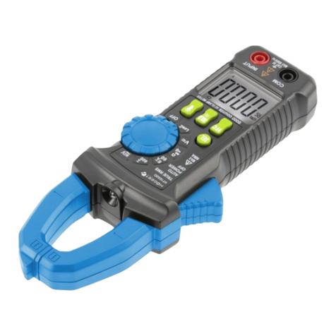
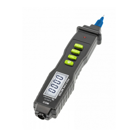
HOGERT HT1E604 User manual

1
Adres producenta/ Adresse des Herstellers/ Manufacturer’s Address/ Адрес производителя
GTV Poland Sp. z o.o. Sp. k., ul. Przejazdowa 21, 05-800 Pruszków
PL
INSTRUKCJA OBSŁUGI
MULTIMETR HT1E604
Dziękujemy za zakup naszego produktu. Wyprodukowany zgodnie z wyso-
kim standardem produkt zapewni lata bezproblemowej pracy pod warun-
kiem stosowania zgodnie z instrukcją i odpowiednio utrzymany.
Niniejsza instrukcja zawiera wszystkie informacje dotyczące bezpieczeń-
stwa, instrukcje obsługi,
specyfikacje i konserwacja miernika, który jest kompaktowy, ręczny i na
baterie.
• Przyrząd wykonuje pomiar napięcia i natężenia prądu stałego DC i prze-
miennego AC, rezystancji, ciągłości dźwięku, diody, hFE, akumulatora,
częstotliwości, pojemność, NCV i temperatury.
• Posiada funkcje wskazania polaryzacji, zatrzymania danych, wskazania
przekroczenia zakresu i automatyczne wyłączanie.
• Multimetr cyfrowy HT1E604 został zaprojektowany zgodnie z normą
EN61010-1 (elektroniczne przyrządy pomiarowe)
W kategorii napięcia (CAT III 600 V, CAT II 1000 V) i stopień zanieczyszczenia
OSTRZEŻENIE
Aby uniknąć możliwego porażenia prądem lub obrażeń ciała i
aby uniknąć możliwego uszkodzenie miernika lub testowanego
sprzętu, przestrzegaj następujących zasad:
• Przed użyciem miernika sprawdź obudowę. Nie używaj miernika, jeśli
jest uszkodzony lub obudowa (lub część obudowy) została usunięta.
Sprawdź pęknięcia i uszkodzenia mechaniczne. Zwróć uwagę na izolację
wokół złączy.
• Sprawdź przewody pomiarowe pod kątem uszkodzonej izolacji lub odsło-
niętego metalu. Sprawdź ciągłość przewodów pomiarowych.
• Nie przykładaj napięcia większego niż napięcie znamionowe wskazane na mierniku, między terminalami lub między dowolnym
terminalem a uziemieniem.
• Przełącznik obrotowy należy ustawić we właściwej pozycji i nie zmieniać podczas wykonywania pomiaru.
• Gdy miernik pracuje przy skutecznym napięciu ponad 60 V w DC lub 30 V RMS w AC, należy zachować szczególną ostrożność przed
porażeniem prądem.
• Użyj odpowiednich zacisków, funkcji i zakresu dla swoich pomiarów.
• Nie używaj ani nie przechowuj miernika w środowisku o wysokiej temperaturze, wilgotności, wybuchowym, łatwopalnym i silnym
polu magnetycznym.
• Podczas korzystania z przewodów pomiarowych nie dotykaj końcówek sondy.
• Odłączyć zasilanie obwodu i rozładować wszystkie wysokie napięcia kondensatory przed testowaniem rezystancji, ciągłości, diod
lub hFE.
• Wymień baterię, gdy tylko pojawi się wskaźnik baterii . Przy słabej baterii miernik może generować fałszywe wartości odczytu.
• Usuń połączenie między przewodami pomiarowymi a obwodem podczas testowania i wyłącz zasilanie miernika przed otwarciem
pokrywy do wymiany baterii.
• Do czyszczenia powierzchni należy używać miękkiej szmatki i łagodnego detergentu. Nie należy używać do tego żadnych środków
ściernych i rozpuszczalników.
• Miernik nadaje się do użytku w pomieszczeniach.
• Wyłącz miernik, gdy nie jest używany, i wyjmij baterię gdy nie używasz przez długi czas. Ciągle sprawdzaj baterię, ponieważ wyciek
może uszkodzić miernik.
2. DANE TECHNICZNE
Wyświetlacz: LCD, aktualizacja co 2 sekundy
Rozmiar ekranu: 64 x 42 mm
Oznaczenie polaryzacji: „-” wyświetla się automatycznie
Wskazanie przekroczenia zakresu: wyświetla się „OL”
Wskaźnik niskiego poziomu naładowania baterii: wyświetla się „ ”
Wybór zakresu: automatyczny lub ręczny
Temperatura pracy: od 0°C do 40°C, wilgotność nie mniej niż 80% RH
Temperatura przechowywania: od -10°C do 50°C, wilgotność względna nie mniejsza niż 85%
Typ baterii: 9 V NEDA 1604, odpowiednik 6F22
Wymiary: 190 x 90 x 35 mm
Waga: około 357 g

2Adres producenta/ Adresse des Herstellers/ Manufacturer’s Address/ Адрес производителя
GTV Poland Sp. z o.o. Sp. k., ul. Przejazdowa 21, 05-800 Pruszków
3. SYMBOLE ELEKTRYCZNE:
Prąd stały DC Bezpiecznik
Prąd przemienny AC Dioda
Prąd stały lub przemienny
DC/AC Test ciągłości
Ważne informacje.
Zapoznaj się z instrukcją AUTO Zakres automatyczny
Niebezpieczeństwo
wysokiego napięcia. Zgodność z dyrektywą Unii
Europejskiej
Uziemienie Podwójna izolacja
Niski poziom baterii
4. OPIS URZĄDZENIA
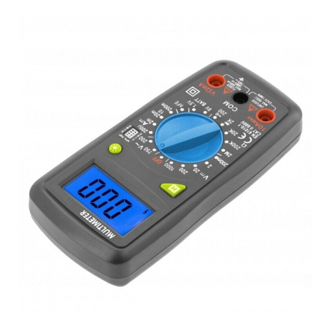
1) miernik cęgowy
2) Ekran LCD
3) Przyciski silikonowe
4) Przełącznik obrotowy funkcji
5) Gniazdo 10 A.
6) Gniazdo μA / mA
7) Gniazdo Com
8) Gniazdo INPUT
9) Obudowa
4-1. Opis przycisków
• PRZYCISK „SELECT”
Naciśnij ten przycisk, aby wybrać Ω” “ ” “ ”lub °C/°F gdy przełącznik funkcji ustawiony jest na pozycji „Ω”.
• PRZYCISK H/
Po naciśnięciu tego przycisku wyświetlacz LCD pokaże ostatni odczyt i symbol „H” pojawi się do ponownego naciśnięcia.
Funkcja podświetlenia - naciśnij ten przycisk przez 2 sekundy podświetlenie zaświeci się, po 15 sekundach podświetlenie wyłączy
się automatycznie.
• PRZYCISK MAX/MIN
Naciśnij ten przycisk, miernik przejdzie w tryb MAX, a na wyświetlaczu LCD pojawi się „MAX” jako wskaźnik. Aktualny odczyt na
ekranie jest maksymalny ze wszystkich odczytów, ponieważ tryb został aktywowany. Naciśnij ponownie, miernik przejdzie w tryb
MIN, a na wyświetlaczu LCD pojawi się „MIN” jako wskaźnik, aktualny odczyt na LCD to minimalny odczyt wszystkich pomiarów.
Naciśnij i przytrzymaj ten przycisk przez około 2 sekundy, aby wyjść z trybów MAX i MIN.
• PRZYCISK RANGE
Zakresy napięcia dla prądu przemiennego i stałego AC/DC, i rezystancji mogą być wybierane ręcznie lub automatycznie przez
naciśnięcie przycisku sterowania zakresem. Naciśnij ten przycisk, aby wybrać potrzebny zakres i tryb kontroli.

3
Adres producenta/ Adresse des Herstellers/ Manufacturer’s Address/ Адрес производителя
GTV Poland Sp. z o.o. Sp. k., ul. Przejazdowa 21, 05-800 Pruszków
• PRZYCISK RELATIVE
Naciśnij ten przycisk, aby ustawić miernik na tryb względny. pojawi się jako wskaźnik. Aby wyjść z trybu względnego, naciśnij
ponownie przycisk, zniknie.
• PRZYCISK Hz / DUTY
Naciśnij ten przycisk, aby wybrać pomiar Hz lub ilość CYKLI przy Hz.
42. JAK ZMIERZYĆ 200 A / 600 A AC
43. JAK PODŁĄCZYĆ ADAPTER
44. WYŚWIETLACZ LCD
1. %Wybór cyklu pracy
2. ˚F Pomiar temperatury w skali Fahrenheita
3. ˚C Pomiar temperatury w skali Celsiusa
4. hFE Test tranzystora hFE
5. Test ciągłości
6. Test diody
7. Podłaczono miernik zewnętrzny
8. AUTO Automatyczny wybór zakresu
9. APO Tryb automatycznego wyłączania
10. HZapis wyniku
11. MAX Maksymalny odczytany wynik pomiaru
12. MIN Minimalny odczytany wynik pomiaru
13. Prąd stały DC
14. Sygnał negatywny
15. Prąd przemienny AC
16. Niski poziom naładowania baterii
17. Tryb relatywny jest aktywny
18. Test baterii
19. NCV Bezdotykowy pomiar napięcia
Dokładność jest gwarantowana przez 1 rok 23 ° C ± 5 ° C mniej niż 80% RH

4Adres producenta/ Adresse des Herstellers/ Manufacturer’s Address/ Адрес производителя
GTV Poland Sp. z o.o. Sp. k., ul. Przejazdowa 21, 05-800 Pruszków
5-1. NAPIĘCIE Prądu stałego DC (automatyczne ustawianie zakresu)
Zakres Rozdzielczość Dokładność
600 mV 0.1 mV ±(0.8% odczytu + 5cyfr)
6 V 1 mV
±(0.8% odczytu + 3cyfr)60 V 10 mV
600 V 100 mV
Impedancja wejściowa: 10 MΩ
Zabezpieczenie przed przeciążeniem: 600 V DC/AC RMS
Max. Napięcie wejściowe: 600 V DC
Pomiar DVC 1000 V zgodnie z CATII
5–2. NAPIĘCIE prądu przemiennego AC (automatyczny wybór zakresu)
Zakres Rozdzielczość Dokładność
600 mV 0.1 mV ±(1.2% odczytu + 8cyfr)
6 V 1 mV
±(1.2% odczytu + 6cyfr)60 V 10 mV
600 V 100 mV
Impedancja wejściowa: 10 MΩ
Zakres częstotliwości: 40 Hz ~ 400 Hz
Zabezpieczenie przed przeciążeniem: 600 V DC / AC rms
Pomiar ACV 750 V zgodnie z CATII CAT III
Max. Napięcie wejściowe: 600 V AC RMS CATIII
5-3. TEMPERATURA
Zakres Rozdzielczość Dokładność
-20 ~1000°C 1°C -40°C~150°C:±(1% + 4)
150°C~1370°C:±(2% + 3)
-4 ~1832°F 1°F -40°F~302°F:±(5% + 4)
302°F~2000°F:±(2.5% + 3)
Zabezpieczenie przed przeciążeniem: Bezpiecznik F0.4A / 600 V
5-4. Natężenie prądu stałego DC
Zakres Rozdzielczość Dokładność
600 µA 0.1 µA
±(0.8% odczytu+ 5cyfr)
6000 µA 1 µA
60 mA 10 µA
600 mA 100 µA
6 A 1 mA ±(1.5% odczytu + 3cyfry)
10 A 10 mA
Zabezpieczenie przed przeciążeniem:
Gniazdo „mA”: bezpiecznik F0,4A / 600 V.
Gniazdo „10A”: bezpiecznik F10A / 600 V.
Maks. Prąd wejściowy: Gniazdo „mA”: 600mA, Gniazdo „10A”: 10A
(Dla pomiarów> 5A: czas trwania <10 sekund, odstęp> 15 minut)
Spadek napięcia: 600µA, 60mA: 60mV,

5
Adres producenta/ Adresse des Herstellers/ Manufacturer’s Address/ Адрес производителя
GTV Poland Sp. z o.o. Sp. k., ul. Przejazdowa 21, 05-800 Pruszków
Zakresy 6000µA, 600mA i 10A: 600mV
5–5. Test tranzystora hFE (podłącz adapter)
Zakres hFE Test natężenia Test napięcia
PNP& NPN 0~1000 Ib≈2µA Vce≈1V
5-6. PRĄD AC
Zakres Rozdzielczość Dokładność
600µA 0.1µA
±(1.5% odczytu+8cyfr)
6000µA 1µA
60mA 10µA
600mA 100µA
10A 100mA ±(2.0% ooczytu +10cyfr)
Zabezpieczenie przed przeciążeniem:
Gniazdo „mA”: bezpiecznik F0,4A / 600 V.
Gniazdo „10A”: bezpiecznik F10A / 600V Max.
Prąd wejściowy:
Gniazdo „mA”: 400mA
Gniazdo „10A”: 10A
(Dla pomiarów> 5A: czas trwania <10 sekund, odstęp> 15 minut)
Spadek napięcia:
Zakresy 600µA, 60mA: 60mV
Zakresy 6000µA, 600mA i 10A: 600mV
Zakres częstotliwości: 40 Hz ~ 400 Hz
5-7. OPORNOŚĆ (automatyczny wybór zakresu)
Zakres Rozdzielczość Dokładność
600 Ω 0.1 Ω
±(1.5% odczytu + 3cyfry)
6 KΩ 1 Ω
60 KΩ 10 Ω
600 KΩ 100 Ω
6 MΩ 1 KΩ
60 MΩ 10 KΩ ±(1.5% odczytu + 5cyfr)
Napięcie obwodu otwartego: około 0,25 V.
Zabezpieczenie przed przeciążeniem: 250 V DC / AC RMS
5-8. Prąd AC 600A przez cęgi
Zakres Rozdzielczość Dokładność
600A 1mV/10A ±(2.5%+10)
200A 1mV/1A

6Adres producenta/ Adresse des Herstellers/ Manufacturer’s Address/ Адрес производителя
GTV Poland Sp. z o.o. Sp. k., ul. Przejazdowa 21, 05-800 Pruszków
5-9 Dioda i ciągłość
Zakres Opis Uwaga
Zostanie wyświetlony
przybliżony spadek
napięcia do przodu
Napięcie w obwodzie
otwartym: około 1,5 V
Wbudowany brzęczyk
zabrzmi, gdy rezystancja
będzie mniejsza niż około
30 Ω
Napięcie w obwodzie
otwartym: około 0,5 V.
Zabezpieczenie przed przeciążeniem: 250 V DC/AC RMS
Dla testu ciągłości: gdy rezystancja wynosi od 30 Ω do 70 Ω, brzęczyk może brzmieć lub nie.
Gdy rezystancja jest większa niż 70 Ω, brzęczyk nie zabrzmi.
5–10. Pojemność
Zakres Rozdzielczość Dokładność
60 nF 10 pF
±(8% odczytu + 5cyfr)
600 nF 100 pF
6 uF 1 nF
60 uF 10 nF
600 uF 100 nF
60 mF 100 uF
Zabezpieczenie przed przeciążeniem: bezpiecznik F0,4A / 600 V.
Napięcie otwartego obwodu: około 0,5 V.
5-11. CZĘSTOTLIWOŚĆ (automatyczny wybór zakresu)
Zakres Dokładność
0~60MHz ±(1.0% + 5)
Zabezpieczenie przed przeciążeniem: 250 V DC/AC RMS
6. POMIARY
6-1. Pomiar napięcia V
1) Podłącz czarny przewód pomiarowy do gniazda „COM”, a czerwony przewód pomiarowy do gniazdo „INPUT”
2) Ustaw przełącznik funkcji w pozycji V lub V . Wybierz zakres automatyczny lub zakres ręczny za pomocą przycisku „RANGE”.
3) W zakresie ręcznym, jeśli mierzona wielkość napięcia nie jest znana wybierz najwyższy zakres.
4) Podłącz przewody pomiarowe do źródła lub mierzonego obwodu.
5) Odczytaj wynik na ekranie. Polaryzacja połączenia czerwonego przewodu będzie wskazana podczas wykonywania pomiaru
prądu stałego
Uwaga:
a. W małym zakresie miernik może wyświetlać niestabilny odczyt, kiedy przewody pomiarowe nie zostały podłączone do obwodu.
Jest to normalne i nie wpłynie na pomiary.
b. W trybie ręcznego zakresu, gdy miernik pokazuje przekroczenie zakresu pojawi się symbol „OL”, należy wybrać wyższy zakres.
c. Aby uniknąć uszkodzenia miernika, nie mierz napięcia, które przekracza 600 V prądu stałego (dla pomiaru napięcia stałego) lub
600 V prądu pzremiennego (dla Pomiar napięcia prądu przemiennego). zgodnie z warunkami CATIII.
6-2. Pomiar natężenia prądu
1) Podłącz czarny przewód testowy do gniazda „COM”. Jeśli wartość mierzona jest mniejsza niż 600 mA, podłącz czerwony prze-
wód pomiarowy do gniazda „mA”. Jeśli prąd wynosi od 600 mA do 10 A, podłącz czerwony przewód do gniazda „10A”.
2) Ustaw przełącznik funkcji na µA , mA lub A . Jeśli bieżąca wielkość mierzona nie jest wcześniej znana, ustaw przełącznik
funkcji do najwyższej pozycji zakresu, a następnie zmniejsz ją i ustaw zadowalającą rozdzielczość.
3) Wybierz pomiar prądu stałego lub pomiaru prądu przemiennego za pomocą przycisku „SELECT”.
4) Brak ręcznej i automatycznej konwersji zakresu dla pomiaru natężenia prądu.
5) Odczytaj wynik na wyświetlaczu. Przy pomiarze obwodu prądu stałego, zostanie również wskazana polaryzacja połączenia
czerwonego przewodu pomiarowego.
Uwaga: Gdy na wyświetlaczu pojawi się nadmierna zakres symbol „OL”, trzeba wybrać większy zakres.

7
Adres producenta/ Adresse des Herstellers/ Manufacturer’s Address/ Адрес производителя
GTV Poland Sp. z o.o. Sp. k., ul. Przejazdowa 21, 05-800 Pruszków
6-3. Pomiar rezystancji
1) Podłącz czarny przewód pomiarowy do gniazda „COM”, a czerwony do gniazda „INPUT” (Uwaga: Biegunowość czerwonego
przewodu pomiarowego jest dodatnia „+”).
2) Ustaw przełącznik funkcji w pozycji „ ” zasięg
3) Wybierz zakres automatyczny lub ręczny za pomocą przycisku „RANGE”. Jeżeli mierzona wielkość rezystancji nie jest znana
wybierz najwyższy zakres.
4) Podłącz przewody pomiarowe do mierzonego obwodu.
5) Przeczytaj odczyt na wyświetlaczu.
Uwaga:
1. Dla pomiarów rezystancji > 1MΩ miernik może zająć kilka sekund, aby ustabilizować odczyt. Jest to normalne w przypadku
wysokiej rezystancji
2. Gdy wejście nie jest podłączone, tj. W obwodzie otwartym, symbol „OL” będzie wyświetlany jako wskaźnik przekroczenia zakresu.
3. Przed pomiarem rezystancji w obwodzie należy upewnić się, że testowany obwód został odłączony od zasilania i wszystkie kon-
densatory są całkowicie rozładowane.
6-4. Test ciągłości
1) Podłącz czarny przewód pomiarowy do gniazda „COM”, a czerwony do gniazdo „INPUT” (Uwaga: Biegunowość czerwonego
przewodu pomiarowego jest dodatnia „+”).
2) Ustaw przełącznik funkcji w pozycji „ ”
3) Naciśnij przycisk „SELECT”, aby wybrać tryb pomiaru ciągłości, i symbol „ ” pojawi się jako wskaźnik..
4)Podłącz przewody pomiarowe do mierzonego obwodu.
5)Jeśli oporność obwodu jest niższa niż około 30 Ω, wbudowany brzęczyk zostanie uruchomiony.
6-5. Test Diody
1) Podłącz czarny przewód pomiarowy do gniazda „COM”, a czerwony do gniazda „INPUT” (Uwaga: Biegunowość czerwonego
przewodu pomiarowego jest dodatnia „+”).
2) Ustaw przełącznik na funkcję „ ”.
3) Naciśnij przycisk „SELECT”, aby wybrać tryb pomiaru ciągłości, i wybierz symbol „ ” pojawi się jako wskaźnik.
4) Podłącz czerwony przewód pomiarowy do anody testowanej diody i czarny przewód pomiarowy do katody.
5) Miernik pokaże przybliżone napięcie przewodzenia diody. Gdy połączenia są odwrócone, na wyświetlaczu pojawi się „OL”.
6-6. Test tranzystora
1) Ustaw przełącznik funkcji w pozycji „hFE”.
2) Podłącz gniazdo wielofunkcyjne do gniazda „COM” i „INPUT”. Zobaczyć Rysunek 2, Nie odwracaj połączenia.
3) Sprawdź, czy tranzystor jest typu NPN czy PNP i zlokalizuj Emiter, Podstawa i kolektor. Włóż przewody tranzystora do testo-
wania w odpowiednie otwory w gnieździe testowym tranzystora adaptera.
4) Wyświetlacz LCD pokaże przybliżoną wartość hFE.
6-7 Pomiar temperatury
1) Ustaw przełącznik funkcji na zakres „ºC / ºF”.
2) Naciśnij przycisk „SELECT”, aby wybrać tryb „° C” lub „° F”. Symbol „° C” lub „° F” pojawi się jako wskaźnik.
3) Włóż czarną (lub „-”) wtyczkę termopary typu K do gniazda „COM”, a czerwona (lub „+”) wtyczka do gniazda „INPUT”.
4) Ostrożnie dotknij końcówkę termopary do obiektu, który ma być zmierzony.
5) Poczekaj chwilę, przeczytaj odczyt na wyświetlaczu.
6-8. Pomiar pojemności
1) Podłącz czarny przewód pomiarowy do gniazda „COM”, a czerwony do gniazdo „INPUT”.
2) Ustaw przełącznik funkcji w pozycji (UWAGA: biegunowość CZERWONY jest dodatni „+”)
3) Podłącz przewody pomiarowe do mierzonego kondensatora i upewnij się, że przestrzegana jest biegunowość połączenia.
Uwaga: kiedy mierzona pojemność jest większa niż 600 uF, potrzeba co najmniej 10 sekund, aby odczyt był stabilny. Kiedy jest
bardzo mała pojemność, do pomiaru wybierz gniazdo wielofunkcyjne, patrz RYSUNEK 3.
6-9. Pomiar częstotliwości
1) Ustaw przełącznik funkcji w wymaganej pozycji „Hz Duty”.
2) Podłącz czarny przewód pomiarowy do gniazda „COM”
3) czerwony do gniazda „INPUT” (uwaga: biegunowość czerwonego przewodu pomiarowego wynosi dodatnie „+”).
4) Przeczytaj odczyt na wyświetlaczu
Uwaga: Nie stosuj więcej niż 250 V RMS na wejściu. Wskazanie jest możliwe napięcie wyższe niż 100 V rms.
6-10 Bezkontaktowy test napięcia
1) Ustaw przełącznik funkcji w zakresie NCV
2) Naciśnij przycisk NCV i przytrzymaj
3) Jeśli w mierzonym obwodzie przepływa prąd zaświeci się lampka i uruchomi brzęczyk
Uwaga: Przed użyciem sprawdź działanie, testując działanie na obwodzie o znanych parametrach
6–11. Pomiar prądu (z cęgiem, opcjonalnie)
1) Jeśli chcesz zmierzyć prąd stały, musisz użyć cęgów DC.
2) Jeśli chcesz zmierzyć prąd przemienny, podłącz ujemny (-) przewód wyjściowy wybranego zacisku do do gniazda „COM”, podłącz
dodatni (+) przewód wyjściowy zacisku do gniazdo „INPUT”.
3) Ustaw przełącznik funkcji w pozycji „ ”
4) Zacisnąć obwód, który ma być zmierzony, za pomocą zacisku. Uwaga: tylko za każdym razem jeden kabel powinien być zaciśnię-
ty, a kabel powinien znajdować się na środku szczęki zaciskowej.
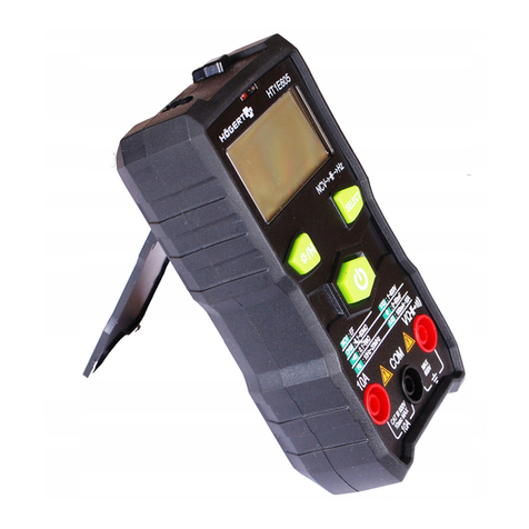
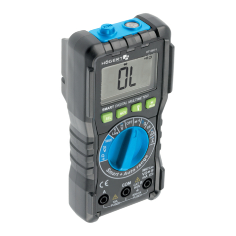
8Adres producenta/ Adresse des Herstellers/ Manufacturer’s Address/ Адрес производителя
GTV Poland Sp. z o.o. Sp. k., ul. Przejazdowa 21, 05-800 Pruszków
5) Przeczytaj odczyt na wyświetlaczu. Do pomiaru prądu stałego, biegunowość dodatniego (+) przewodu wyjściowego zacisku będzie
oznaczona
6) Domyślnym akcesorium dla produktu jest zacisk prądu zmiennego.
Uwaga: Cęgi nie mogą być testowane na prąd większy niż 600A.
a. Nie dotykaj testowanego obwodu ręką
b. Dostosuj zakres miernika i czułości cęgów:
I: Czułość pasującego zacisku wynosi 1A / 1mV. Jeśli używasz pasujący zacisk, obecna wskazana wartość jest taka sama jak zmie-
rzona wartość.
II: Jeśli używasz cęgów, których czułość nie jest równa 1mV / 1A, pomnóż obecny odczyt przez współczynnik, który jest określony dla
użytego zacisku, wynikiem jest zmierzona wartość. Aby określić współczynnik, zapoznaj się z instrukcją zacisku, którego używasz.
III: na przykład, jeśli używasz cęgów o czułości równej 1mV / 10A plus
Wyświetlacz LCD pokazuje cyfry po dziesięciu, aby uzyskać bieżący wynik odczytu.
Automatyczne wyłączanie
Jeśli miernik nie będzie używany przez około 15 minut, wyłączy się automatycznie. Aby włączyć ponownie, wystarczy obrócić prze-
łącznik funkcji lub nacisnąć przycisk „SELECT” lub „RANGE” przez ponad 2 sekundy. Żeby wyłączyć funkcję AutoWYŁACZENIE,
naciśnij przycisk „ Hz / Duty ” , i jednocześnie obrócić przełącznik funkcji. Symbol „APO” zniknie z ekranu.
7. Wymiana baterii i bezpiecznika
Jeśli znak „ ” pojawi się na wyświetlaczu, oznacza to, że bateria powinna być wymieniona. Odkręć śruby i otwórz tylną obudo-
wę, wymień baterie (NEDA 1604, 6F22 lub równoważna, patrz Rysunek 4)
Bezpiecznik rzadko wymaga wymiany i jest prawie zawsze przepalany błądem operatora. Aby wymienić bezpieczniki, otwórz
pokrywębaterii,wymieńuszkodzonybezpieczniknanowyopodanychwartościachznamionowych.Zainstalujponownie baterię zakryj
i zablokuj tę pokrywę. (patrz rysunek 4)
Ostrzeżenie
Aby uniknąć błędnych odczytów, które mogłyby doprowadzić do porażenia prądem elektrycznym lub obrażenia ciała, wymień bate-
rię, gdy tylko wskaźnik baterii („ „) pojawia się. Aby zapobiec uszkodzeniom lub obrażeniom, instaluj wyłącznie bezpieczniki za-
stępcze o podanych parametrach natężenie prądu, napięcia i znamionowe przerwania. Odłącz przewody testowe przed otwarciem
tylnej pokrywy .
1) Wymiana akumulatora i bezpiecznika powinna nastąpić dopiero po odłączeniu przewodów pomiarowych i zasilania.
2) Poluzuj śruby odpowiednim śrubokrętem i zdejmij dolną część obudowy.
3) Miernik jest zasilany z jednej baterii 9 V (IEC 6F22, NEDA 1604,JIS006P). Zatrzasnąć złącza na zaciskach nowej baterii i ponownie
włóżyć do górnej części obudowy. Umieść przewody akumulatora tak, aby nie zostały ściśnięte .
Ten miernik wykorzystuje dwa bezpieczniki:
Bezpiecznik 1: 400mA, 600V, SZYBKI, min. Ocena przerwania 20000A, Ø10X38mm
Bezpiecznik 2: 10 A, 600 V, SZYBKI, min. Ocena przerwania 20000A, Ø10X38mm
Aby wymienić bezpiecznik, wykręć śruby na ramie nośnej, bez wyjmowania miernik z obudowy, bez zdejmowania tylnej pokrywy,
wymień bezpiecznik z nową jedną z tych samych ocen. Ponownie podłącz ramkę nośną, zainstaluj ponownie śruby

9
Adres producenta/ Adresse des Herstellers/ Manufacturer’s Address/ Адрес производителя
GTV Poland Sp. z o.o. Sp. k., ul. Przejazdowa 21, 05-800 Pruszków
EN
USER’S MANUAL
MULTIMETER HT1E604
Thank you for purchasing our product. Manufactured to a high standard, this
product will, if used according to these instructions, and properly mainta-
ined, give you years of trouble free performance.
• This manual contains all safety information, operating instructions, spe-
cifications and maintenance of the meter, which is compact, manual and
battery-powered. The instrument measures DC and AC voltage current,
resistance, sound continuity, diode, hFE, battery, frequency, capacity, NCV
and temperature.
• It has polarity indication, data retention, overrange indication and Auto
Power Off functions. The HT1E604 digital multimeter is designed
in accordance with EN61010-1 (electronic measuring instruments)
In voltage category (CAT III 600 V, CAT II 1000 V) and pollution degree 2.
WARNING
To avoid possible electric shock or personal injury and to avoid
possible damage to the meter or equipment being tested,
observe the following rules:
• Check the housing before using the meter. Do not use the meter if it
is damaged or the housing (or part of the housing) has been removed.
Check cracks and mechanical damage. Pay attention to the insulation
around the connectors.
• Check the test leads for damaged insulation or exposed metal.
Check the continuity of the measurement wires.
• Do not apply a voltage greater than the rated voltage indicated on the
meter, between terminals or between any terminal and ground.
• The rotary switch must be set in the correct position and not changed
during the measurement.
• When the meter operates at an effective voltage of over 60 V in DC or 30 V RMS in AC, special care must be taken against an electric
shock.
• Use the appropriate terminals, functions and range for your measurements.
• Do not use or store the meter in an environment with high temperature, humidity, explosive, flammable or strong magnetic field.
• Do not touch the probe tips when using the test leads.
• Disconnect the circuit power and discharge all high voltage capacitors before testing resistance, continuity, diodes or hFE.
• Replace the battery as soon as the battery indicator appears . With a low battery, the meter can generate false reading values.
• Remove the connection between the test leads and the circuit during testing and turn off the power to the meter before opening the
cover to replace battery.
• Use a soft cloth and mild detergent to clean the surface. Do not use any abrasives or solvents.
• The meter is suitable for indoor use.
• Turn the meter off when not in use, and remove the battery when not in use for a long time. Continuously check the battery, as a
leak may damage the meter.
2. TECHNICAL DATA
Display: LCD, updated every 2 seconds
Screen size: 64 x 42 mm
Polarity marking: „-” displays automatically
Overrange indication: „OL” displays
Low battery indicator: displays „ „
Range selection: automatic or manual
Operating temperature: 0°C to 40°C, humidity not less than 80% RH
Storage temperature: -10°C to 50°C, relative humidity not less than 85%
Battery type: 9 V NEDA 1604, equivalent to 6F22
Dimensions: 190 x 90 x 35 mm
Weight: approximately 357 g

10 Adres producenta/ Adresse des Herstellers/ Manufacturer’s Address/ Адрес производителя
GTV Poland Sp. z o.o. Sp. k., ul. Przejazdowa 21, 05-800 Pruszków
3. ELECTRICAL SYMBOLS:
Direct Current DC Fuse
Alternating Current AC Diode
Direct or alternating
current DC/AC Continuity test
Important safety
information. AUTO Automatic range selection
High voltage can occur. . Compliant with
the European Union
Directive
Ground Double insulation
Low battery
4. DEVICE DESCRIPTION
1) Clamp meter
2) LCD screen
3) Silicone buttons
4) Function rotary switch
5) 10 A socket.
6) μA / mA socket
7) Com socket
8) INPUT socket
9) Housing
4-1. Buttons description
• Select button
Press this button to select „Ω”, ” “ ” “ ”or °C/°F when the function switch is set to „Ω”.
• BUTTON H/
When this button is pressed, the LCD display will show the last reading and the „H” symbol displays until pressed again. Backlight
function - press this button for 2 seconds the backlight will light up, after 15 seconds the backlight will turn off automatically.
• BUTTON MAX/MIN
Press this button, the meter will go into MAX mode and the LCD will display „MAX” as an indicator. The current reading on the
screen is the maximum of all readings because the mode has been activated. Press again, the meter will go into MIN mode and
„MIN” will display as an indicator on the LCD, the current reading on the LCD is the minimum reading of all measurements. Press
and hold this button for about 2 seconds to exit the MAX and MIN modes.
• RANGE BUTTON
The voltage ranges for AC/DC, DC and resistance can be selected manually or automatically by pressing the range control button.
Press this button to select the needed range and control mode.

11
Adres producenta/ Adresse des Herstellers/ Manufacturer’s Address/ Адрес производителя
GTV Poland Sp. z o.o. Sp. k., ul. Przejazdowa 21, 05-800 Pruszków
• BUTTON RELATIVE
Press this button to set the meter to relative mode. displays as an indicator. To exit relative mode, press the button again,
will disappear.
• Hz / DUTY BUTTON
Press this button to select the Hz measurement or the number of CYCLES at Hz.
42. HOW TO MEASURE 200 A / 600 A AC
43. HOW TO CONNECT THE ADAPTER
44. LCD DISPLAY
1. %Choice of work cycle
2. ˚F Temperature measurement on the Fahrenheit scale
3. ˚C Temperature measurement on the Celsius scale
4. hFE HFE transistor test
5. Continuity test
6. Diode test
7. External meter was connected
8. AUTO Automatic range selection
9. APO Auto Power Off mode
10. HData hold
11. MAX Maximum measurement reading
12. MIN Minimum measurement reading
13. Direct current DC
14. Negative signal
15. Alternating current AC
16. Low battery
17. Relative mode is active
18. Battery test
19. NCV Non-contact voltage measurement
Accuracy is guaranteed for 1 year 23 ° C ± 5 ° C less than 80% RH

12 Adres producenta/ Adresse des Herstellers/ Manufacturer’s Address/ Адрес производителя
GTV Poland Sp. z o.o. Sp. k., ul. Przejazdowa 21, 05-800 Pruszków
5-1. DC voltage (automatic range setting)
Range Resolution Accuracy
600 mV 0.1 mV ±(0.8% reading + 5 digits)
6 V 1 mV
±(0.8% reading + 3 digits)60 V 10 mV
600 V 100 mV
1000 V 1 V ±(1.0% reading + 5 digits)
Input impedance: 10 MΩ
Overload protection: 600 V DC/AC RMS
Max. Input voltage: 600 V DC
DVC 1000 V measurement according to CATII
5-2. AC voltage (automatic range selection)
Range Resolution Accuracy
600 mV 0.1 mV ±(1.2% reading + 8 digits)
6 V 1 mV
±(1.2% reading + 6 digits)60 V 10 mV
600 V 100 mV
750 V 1 V ±(1.2% reading + 8 digits)
Input impedance: 10 MΩ
Frequency range: 40 Hz ~ 400 Hz
Overload protection: 600 V DC / AC rms
Measurement of ACV 750 V in accordance with CATII CAT III
Max. Input voltage: 600 V AC RMS CATIII
5-3. TEMPERATURE
Range Resolution Accuracy
-20~1000°C 1°C -40°C~150°C:±(1% + 4)
150°C~1370°C:±(2% + 3)
-4~1832°F 1°F -40°F~302°F:±(5% + 4)
302°F~2000°F:±(2.5% + 3)
Overload protection: Fuse F0.4A / 600 V.
5-4. DC voltage
Range Resolution Accuracy
600 µA 0.1 µA
±(0.8% reading + 5 digits)
6000 µA 1 µA
60 mA 10 µA
600 mA 100 µA
6 A 1 mA ±(1.5% reading + 3 digits)
10 A 10 mA
Overload protection:
Socket „mA”: fuse F0.4A / 600 V.
Socket „10A”: fuse F10A / 600 V.

13
Adres producenta/ Adresse des Herstellers/ Manufacturer’s Address/ Адрес производителя
GTV Poland Sp. z o.o. Sp. k., ul. Przejazdowa 21, 05-800 Pruszków
Max. Output current: Socket „mA”: 600mA, Socket „10A”: 10A
(For measurements> 5A: duration <10 seconds, interval> 15 minutes)
A drop in voltage: 600µA, 60mA: 60mV,
Ranges 6000µA, 600mA and 10A: 600mV
5-5. hFE transistor test (connect adapter)
Range hFE Amperage test Voltage test
PNP& NPN 0~1000 Ib≈2µA Vce≈1V
5-6. AC CURRENT
Range Resolution Accuracy
600 µA 0.1 µA
±(1.5% reading +8 digits)
6000 µA 1 µA
60 mA 10 µA
600 mA 100 µA
10 A 100 mA ±(2.0% reading +10 digits)
Overload protection:
Socket „mA”: fuse F0.4A / 600 V.
Socket „10A”: fuse F10A / 600V Max.
Output current:
Socket „mA”: 400mA
Socket „10A”: 10A
(For measurements> 5A: duration <10 seconds, interval> 15 minutes)
A drop in voltage:
Range 600µA, 60mA: 60mV
Ranges 6000µA, 600mA and 10A: 600mV
Frequency range: 40 Hz ~ 400 Hz
5-7. Resistance (automatic range selection)
Range Resolution Accuracy
600 Ω 0.1 Ω
±(1.5% reading + 3 digits)
6 KΩ 1 Ω
60 KΩ 10 Ω
600 KΩ 100 Ω
6 MΩ 1 KΩ
60 MΩ 10 KΩ ±(1.5% reading + 5 digits)
Open circuit voltage: about 0.25 V.
Overload protection: 250 V DC / AC RMS
5-8. PAC 600A current through pliers
Range Resolution Accuracy
600A 1mV/10A ±(2.5%+10)
200A 1mV/1A

14 Adres producenta/ Adresse des Herstellers/ Manufacturer’s Address/ Адрес производителя
GTV Poland Sp. z o.o. Sp. k., ul. Przejazdowa 21, 05-800 Pruszków
5-9 Diode and continuity
Range Description Note
An approximate for-ward
drop in voltage will be
displayed
The voltage in an open
circuit is about 1.5 V.
Built-in buzzer sounds
when the resistance is less
than about 30 Ω
The voltage in an open
circuit is about 0.5 V.
Overload protection: 250 V DC/AC RMS
For the continuity test: when the resistance is 30 Ω to 70 Ω, the buzzer may or may not sound.
When the resistance is greater than 70 Ω, the buzzer will not sound.
5–10. Capacity
Range Resolution Accuracy
60 nF 10 pF
±(8% reading + 5 digits)
600 nF 100 pF
6 uF 1 nF
60 uF 10 nF
600 uF 100 nF
60 mF 100 uF
Overload protection: fuse F0.4A / 600 V.
Open circuit voltage: about 0.5 V.
5-11. FREQUENCY (automatic range selection)
Range Accuracy
0~60MHz ±(1.0% + 5)
Overload protection: 250 V DC/AC RMS
5–12. Battery
Range Resolution Discharge resistance
1.5 V 0.01 V 25 Ω
3 V 0.01 V 90 Ω
9 V 0.01 V 220 Ω
Overload protection 1.5 V and 3 V.
Ranges Fuse F0.4A / 250V 9 V.
Range 250 VDC / AC RMS
The battery voltage is shown on the LCD.
6. MEASUREMENTS
6-1. Voltage measurement
1) Connect the black lead to the COM socket and the red lead to the IMPUT socket
2) Set the function switch to V lub V . Select automatic range or manual range with the „RANGE” button.
3) In the manual range, if the measured voltage is not known, select the highest range.
4) Connect test leads to the source or measured circuit.
5) Read the result on the screen. The polarity of the red lead connection will be indicated during the DC measurement.
Note:
a. |n a small range, the meter may display an unstable reading when the test leads are not connected to the circuit. This is normal
and will not affect the measurements.
b. In the manual range mode, when the meter shows an overrange, the symbol „OL” displays, select a higher range.
c. To avoid damage to the meter, do not measure a voltage over 600 V DC (for DC measurement) or 600 V AC (for AC measure-
ment). Complies with CATIII.

15
Adres producenta/ Adresse des Herstellers/ Manufacturer’s Address/ Адрес производителя
GTV Poland Sp. z o.o. Sp. k., ul. Przejazdowa 21, 05-800 Pruszków
6-2. Current measurement
1) Connect the black lead to the COM socket. If the measured value is less than 600 mA, connect the red lead to mA socket. If the
current is between 600 mA and 10 A, connect the red lead to 10A socket.
2) Set the function switch to µA , mA or A . If the current measurement is not known in advance, set the function switch to the
highest position of the range, then reduce it and set a satisfactory resolution.
3) Select DC or AC measurement using SELECT button.
4) No manual or automatic range conversion for current measurement.
5) Read the result on the display. When measuring the DC circuit, the polarity of the red lead connection will also be indicated.
Note: If the display shows overrange OL, a larger range must be selected.
6-3. Resistance measurement
1) Connect the black lead to the COM socket and the red lead to INPUT socket (Note: The polarity of the red lead is positive „+”).
2) Set the function switch to „ ” range
3) Select automatic or manual range with RANGE button. If the measured resistance is not known choose the highest range.
4) Connect test leads to the measured circuit.
5) Read the reading on the display.
Note:
1. For resistance measurements > 1MΩ the meter may take several seconds to stabilize the reading. This is normal for high
resistance
2. When the input is not connected, i.e. in an open circuit, the “OL” symbol will be displayed as an overrange indicator.
3. Before measuring the resistance in a circuit, make sure that the circuit being tested has been disconnected from the power
supply and all capacitors are completely discharged.
6-4. Continuity test
1) Connect the black lead to the COM socket and the red lead to the IMPUT socket (Note: The polarity of the red lead is positive
„+”).
2) Set the function switch to „ ”
3) Press the SELECT button to select the continuity measurement mode, and the symbol „ ” will appear as an indicator.
4) Connect test leads to the measured circuit.
5) If the circuit resistance is less than about 30 Ω, the built-in buzzer will be activated.
6-5. Diode test
1) Connect the black lead to the COM socket and the red lead to the IMPUT socket (Note: The polarity of the red lead is positive „+”).
2) Set the switch to the function „ ”.
3) Press the SELECT button to select the continuity measurement mode, and select the symbol „ ”.
4) Connect the red test lead to the anode of the tested diode and the black test lead to the cathode.
5) The meter will show the approximate conduction voltage of the diode. When connections are reversed, OL will appear on the
display.
6-6. Transistor test
1) Set the function switch to „hFE”.
2) Plug the multifunction socket into COM and INPUT sockets. See Figure 2, Do not invert the connection.
3) Check if the transistor is NPN or PNP type and locate the Emitter, Base and Collector. Insert transistor cables for testing in
the appropriate holes in the test jack of the adapter transistor.
4) The LCD display will show the approximate hFE value.
6-7 Temperature measurement
1) Set the function switch to „ºC / ºF”.
2) Press the Select button to select „° C” or „° F” mode. The symbol „° C” or „° F” will appear as an indicator.
3) Insert the black (or „-”) K-type thermocouple plug into the COM socket and the red (or „+”) plug into the INPUT socket.
4) Carefully touch the thermocouple tip to the object to be measured.
5) Wait a moment, read the reading on the display.
6-8. Capacity measurement:
1) Connect the black lead to the COM socket and the red lead to the INPUT socket.
2) Set the function switch to „ ” (NOTE: RED polarity is positive „+”)
3) Connect the test leads to the measured capacitor and make sure that the polarity of the connection is observed. Note: when
the capacity measured is greater than 600 uF, it takes at least 10 seconds for the reading to be stable. When the capacity is
very low, select the multifunctional socket to measure, see FIGURE 3.
6-9. Frequency measurement
1) Set the function switch to the required „Hz Duty” position.
2) Connect the black lead to the COM socket
3) the red lead to the IMPUT socket (note: the polarity of the red lead is positive „+”).
4) Read the reading on the display
Note: Do not use more than 250 V RMS at the input. It is possible to indicate a voltage higher than 100 V rms,

16 Adres producenta/ Adresse des Herstellers/ Manufacturer’s Address/ Адрес производителя
GTV Poland Sp. z o.o. Sp. k., ul. Przejazdowa 21, 05-800 Pruszków
6-10 Non-contact voltage test
1) Set the function switch in the NCV range
2) Press and hold the NCV button
3) If there is a current flow in the measured circuit, the lamp lights up and the buzzer activates
Note: Before use, check the operation by testing the circuitry with known parameters.
6–11. Battery measurement
1) Connect the black lead to the COM socket and the red lead to lNPUT socket (note: the polarity of the red lead is positive „+”).
2) Depending on the other battery type (1.5 V, 3 V, 9 V), set the function switch to the needed battery range.
3) Connect the test leads to the tested battery.
4) Read the reading on the display. The polarity of the red lead will be indicated.
6–12. Current measurement (with clamp, optional)
1) Use DC clamps to measure DC
2) To measure AC current, connect the negative (-) lead of the selected terminal to the COM socket, connect the positive (+) lead of the
terminal to the IMPUT socket.
3) Set the function switch to „ ”
4) Clamp the circuit to be measured with a clamp. Note: Only one lead should be crimped each time and the lead should be in the
middle of the clamping jaw.
5) Read the reading on the display. For DC measurement, the polarity of the positive (+) output lead of the terminal will be marked
6) The default accessory for the product is the AC terminal.
Note: The clamps must not be tested for a current greater than 600A.
a. Do not touch the circuit being tested by hand
b. Adjust the range of the meter and the sensitivity of the clamps:
i: The sensitivity of the matching terminal is 1A / 1mV. If you use the matching terminal, the current indicated value is the same as the
measured value.
ii: If you are using a clamp with a sensitivity of less than 1mV / 1A, multiply the current reading by the coefficient that is specified for
the one used of the terminal, the result is the measured value. To determine the coefficient, refer to the manual of the clamp you
are using.
iii: for example, if you use pliers with a sensitivity of 1mV / 10A plus
The LCD displays digits after ten to get the current reading result.
Auto Power Off
If the meter is not used for about 15 minutes, it will power off automatically. To switch on again, simply turn the function switch or
press the SELECT or RANGE button for more than 2 seconds. To deactivate the Auto Power Off function, press the Hz/Duty button
and at the same time turn the function switch. The APO symbol will disappear from the screen.
7. Battery and fuse replacement
If the „ ” appears on the display, the battery should be replaced. Loosen the screws and open the rear casing, replace batteries
(NEDA 1604, 6F22 or equivalent, see Figure 4)
The fuse rarely needs to be replaced and is almost always burned by operator error. To replace the fuses, open the battery cover,
replace the faulty fuse with a new one with the specified ratings. Reinstall the battery cover and lock the cover. (see Figure 4)
Warning To avoid incorrect readings that could lead to an electric shock or injury, replace the battery as soon as the battery indicator
(„ „) appears.
To prevent damage or injury, only install replacement fuses with the specified current, voltage and interrupting rating.
Disconnect the test leads before opening the rear cover.
1) Replacement of the battery and fuse should be done only after disconnecting the test leads and power supply.
2) Loosen the screws with a suitable screwdriver and remove the bottom of the housing.
3) The meter is powered by one 9 V battery (IEC 6F22, NEDA 1604, JIS006P). Snap on the terminals of the new battery and then put
it back to the top of the housing. Place the battery wires so that they are not squeezed.
This meter uses two fuses:
Fuse 1: 400mA, 600V, FAST, min. Interrupting rating 20000A, Ø10X38mm
Fuse 2: 10 A, 600 V, FAST, min. Interrupting rating 20000A, Ø10X38mm
To replace the fuse, remove the screws on the support frame, without removing the meter from the housing, without removing the
back cover, replace the fuse with a new one of the same ratings. Reconnect the support frame, reinstall the screws

17
Adres producenta/ Adresse des Herstellers/ Manufacturer’s Address/ Адрес производителя
GTV Poland Sp. z o.o. Sp. k., ul. Przejazdowa 21, 05-800 Pruszków
DE
BENUTZERHANDBUCH
MULTIMETER HT1E604
Vielen Dank, dass Sie sich für unser Produkt entschieden haben.
Hergestellt nach hohen Standard, wird dieses Produkt, wenn den Anwe-
isungen entsprechend verwendet, und ordnungsgemäß gewartet, Ihnen
störungsfreien Betrieb garantieren.
• Die vorliegende Anleitung enthält alle Informationen zur Sicherheit, Be-
dienung, Spezifikation und Pflege des Messgeräts, das ein kompaktes,
manuelles und batteriebetriebenes Gerät ist.
• Das Messgerät führt Messungen von Spannung und Stromstäkre im Gle-
ichstrombereich DC und Wechselstrombereich AC, Widerstand, Konti-
nuität, Diode hFE, Akku, Frequenz, Kapazität, NCV und Temperatur durch.
• Es besitzt Funktionen zur Anzeige der Polung, Halten von Daten, Anzeige
der Überschreitung des Messbereichs und automatischem Abschalten.
• Das Digital-Multimeter HT1E604 wurde gemäß der Norm EN61010-1 en-
tworfen (elektronische Messgeräte)
In der Spannungskategorie (CAT III 600 V, CAT II 1000 V) und Verunreini-
gungsgrad 2.
WARNUNG
Um mögliche Stromschläge oder Körperverletzungen sowie
Schäden am Messgerät oder den geprüften Geräten zu verme-
iden, halten Sie die nachstehenden Regeln ein:
• Überprüfen Sie vor der Verwendung des Messgeräts das Gehäuse.
Verwenden Sie das Messgerät nicht, wenn es beschädigt ist oder das
Gehäuse (bzw. ein Teil des Gehäuses) entfernt wurde. Überprüfen Sie
Sprünge und mechanische Schäden. Achten Sie auf die Isolierung um die
Anschlüsse.
• Prüfen Sie die Messkabel im Hinblick auf beschädigte Isolierung oder offengelegtes Metall. Überprüfen Sie die Kontinuität der
Messkabel.
• Legen Sie keine größere Spannung als die auf dem Messgerät angegebene Nennspannung, zwischen den Enden oder zwischen
einem beliebigen Ende und der Erdung an.
• Stellen Sie den Drehschalter in die richtige Position und ändern Sie ihn nicht während der Messung.
• Wenn das Messgerät bei einer Effektivspannung über 60 V in DC oder 30 V, RMS in AC arbeitet, ist besondere Vorsicht zu wahren,
im Hinblick auf die Stromschlaggefahr.
• Verwenden Sie die entsprechenden Klemmen, Funktionen und den richtigen Bereich für Ihre Messungen.
• Verwenden oder lagern Sie das Messgerät in keinen Umfeldern mit hoher Temperatur, Feuchtigkeit, explosiven und leicht brenn-
baren Umfeldern oder solchen mit einem starken Magnetfeld.
• Berühren Sie während der Verwendung der Messkabel nicht die Spitzen der Sonden.
• Trennen Sie die Stromversorgung des Stromkreises und entladen Sie alle Hochspannungs-Kondensatoren vor Messungen des
Widerstands, der Kontinuität, Dioden oder hFE.
• Tauschen Sie die Batterie, sobald die Batterieanzeige erscheint . Bei schwachem Batteriestand kann das Messgerät falsche Werte
anzeigen.
• Entfernen Sie die Verbindung zwischen den Messkabeln und dem Stromkreis während des Testvorgangs und schalten Sie die
Stromversorgung des Messgeräts vor dem Öffnen des Batteriefachs ab.
• Verwenden Sie zur Reinigung der Oberfläche ein weiches Tuch und ein mildes Reinigungsmittel. Verwenden Sie dazu keine scheu-
ernden Reinigungsmittel oder Lösungsmittel.
• Das Messgerät ist für den Gebrauch im Inneren von Räumen ausgelegt.
• Schalten Sie das Messgerät aus, wenn es nicht verwendet wird, und nehmen Sie die Batterie heraus, wenn es über einen längeren
Zeitraum nicht verwendet wird. Überprüfen Sie laufend die Batterie, da ein Leck aus dieser das Messgerät beschädigen kann.
2. TECHNISCHE DATEN
Anzeige: LCD, Aktualisierung alle 2 Sekunden
Bildschirmgröße: 64 x 42 mm
Kennzeichnung der Polung: „-” wird automatisch angezeigt
Anzeige der Bereichsüberschreitung: „OL” wird angezeigt
Anzeige eines niedrigen Batterieladestands: „ ” wird angezeigt
Bereichsauswahl: automatisch oder manuell
Betriebstemperatur: zwischen 0 °C und 40 °C, Luftfeuchtigkeit nicht weniger als 80 % RH
Lagertemperatur: zwischen -10 °C und 50 °C, relative Luftfeuchtigkeit nicht weniger als 85 %
Batterietyp: 9 V NEDA 1604, Äquivalent zu 6F22
Abmessungen: 190 x 90 x 35 mm
Gewicht: etwa 357 g

18 Adres producenta/ Adresse des Herstellers/ Manufacturer’s Address/ Адрес производителя
GTV Poland Sp. z o.o. Sp. k., ul. Przejazdowa 21, 05-800 Pruszków
3. ELEKTRISCHE SYMBOLE:
Gleichstrom DC Sicherung
Wechselstrom AC Diode
Gleich- oder Wechselstrom
DC/AC Kontinuitätstest
Wichtige
Sicherheitsinformationen. AUTO Automatische
Bereichsauswahl
Hochspannung möglich. Gemäß der Richtlinie der
Europäischen Union
Erdung. Doppelte Isolierung.
Niedriger
Batterieladestand
4. GERATEBESCHREIBUNG
1) Zangenstrommesser
2) LCD-Display
3) Silikontasten
4) Funktions-Drehregler
5) Buchse 10 A.
6) Buchse μA / mA
7) Buchse Com
8) Buchse INPUT
9) Gehäuse
4-1. Tastenbeschreibung
• TASTE „SELECT”
Drücken Sie diese Taste für die Auswahl von Ω” “ ” “ ”oder °C/°F wenn der Funktionsschalter in der Position „Ω” eingestellt ist.
• TASTE H/
Nach dem Drücken dieser Taste zeigt die LCD-Anzeige den letzten Messwert an, und das Symbol „H“ erscheint solange, bis die
Taste erneut gedrückt wird. Beleuchtungs-Funktion - drücken Sie diese Taste 2 Sekunden lang, die Beleuchtung wird eingeschal-
tet, nach 15 Sekunden schaltet die Beleuchtung sich wieder automatisch aus.
• TASTE MAX/MIN
Drücken Sie diese Taste, das Messgerät wechselt in den MAX-Modus, auf dem LCD-Bildschirm erscheint „MAX“ als Anzeige. Die
aktuelle Anzeige auf dem Bildschirm ist die maximale aller Messwert-Anzeigen, da der Modus aktiviert wurde. Drücken Sie er-
neut, das Messgerät wechselt in den MIN-Modus, auf dem LCD-Bildschirm erscheint „MIN“ als Anzeige, die aktuelle Anzeige am
LCD-Bildschirm ist die minimale aller Messwert-Anzeigen. Drücken und halten Sie diese Taste etwa 2 Sekunden lang gedrückt,
um die MAX- und MIN-Modi zu verlassen.
• RANGE TASTE
Bereiche der Wechsel- und Gleichspannung AC/DC, und des Widerstands können manuell oder automatisch ausgewählt werden, durch
Drücken der Taste zur Steuerung des Messbereichs. Drücken Sie diese Taste, um den benötigten Bereich und Steuermodus zu wählen.

19
Adres producenta/ Adresse des Herstellers/ Manufacturer’s Address/ Адрес производителя
GTV Poland Sp. z o.o. Sp. k., ul. Przejazdowa 21, 05-800 Pruszków
• TASTE RELATIVE
Drücken Sie diese Taste, um das Messgerät in den relativen Modus einzustellen. erscheint als
Anzeige. Um den relativen Modus zu verlassen, drücken Sie erneut die Taste, verschwindet
• TASTE Hz / DUTY
Drücken Sie diese Taste, um die Messung von Hz oder der Anzahl der ZYKLEN bei Hz zu wählen
42. WIE MAN 200 A / 600 A AC MISST
43. WIE MAN DEN ADAPTER ANSCHLIESST
44. LCDANZEIGE
1. %Auswahl des Arbeitszyklus
2. ˚F Temperaturmessung in Fahrenheit-Skala
3. ˚C Temperaturmessung in Celsius-Skala
4. hFE Transistor-Test hFE
5. Kontinuitätstest
6. Diodentest
7. Externes Messgerät angeschlossen
8. AUTO Automatische Bereichsauswahl
9. APO Automatischer Abschaltmodus
10. HErgebnis-Speicherung
11. MAX Maximal abgelesenes Messergebnis
12. MIN Minimal abgelesenes Messergebnis
13. Gleichstrom DC
14. Negatives Signal
15. Wechselstrom AC
16. Niedriger Batterieladestand
17. Relativer Modus ist aktiv
18. Batterietest
19. NCV Kontaktlose Spannungsmessung
Die Genauigkeit wird garantiert: 1 Jahr lang, 23 ° C ± 5 ° C weniger als 80 % RH

20 Adres producenta/ Adresse des Herstellers/ Manufacturer’s Address/ Адрес производителя
GTV Poland Sp. z o.o. Sp. k., ul. Przejazdowa 21, 05-800 Pruszków
5-1. Gleichspannung DC (automatische Bereichseinstellung)
Bereich Auflösung Genauigkeit
600 mV 0.1 mV ±(0.8 % Anzeige + 5 Stellen)
6 V 1 mV
±(0.8 % Anzeige + 3 Stellen)60 V 10 mV
600 V 100 mV
1000 V 1 V ±(1.0% Anzeige + 5 Stellen)
Eingangsimpedanz: 10 MΩ
Überlastungsschutz: 600 V DC/AC RMS
Max. Eingangsspannung: 600 V DC
Messung DVC 1000 V gemäß CATII
5-2. Wechselspannung AC (automatische Bereichsauswahl)
Bereich Auflösung Genauigkeit
600 mV 0.1 mV ±(1.2% Anzeige + 8 Stellen)
6 V 1 mV
±(1.2% Anzeige + 6 Stellen)60 V 10 mV
600 V 100 mV
750 V 1 V ±(1.2% Anzeige + 8 Stellen)
Eingangsimpedanz: 10 MΩ
Frequenzbereich: 40 Hz ~ 400 Hz
Überlastungsschutz: 600 V DC / AC rms
Messung ACV 750 V gemäß CATII CAT III
Max. Eingangsspannung: 600 V AC RMS CATIII
5-3. TEMPERATUR
Bereich Auflösung Genauigkeit
-20~1000°C 1°C -40°C~150°C:±(1% + 4)
150°C~1370°C:±(2% + 3)
-4~1832°F 1°F -40°F~302°F:±(5% + 4)
302°F~2000°F:±(2.5% + 3)
Überlastungsschutz: Sicherung F0.4A / 600 V.
5-4. DC Gleichstrom
Bereich Auflösung Genauigkeit
600 µA 0.1 µA
±(0.8 % Anzeige + 5 Stellen)
6000 µA 1 µA
60 mA 10 µA
600 mA 100 µA
6 A 1 mA ±(1.5 % Anzeige + 3 Stellen)
10 A 10 mA
Überlastungsschutz:
Buchse „mA”: Sicherung F0,4A / 600 V.
Buchse „10A”: Sicherung F10A / 600 V.
Table of contents
Languages:
Other HOGERT Multimeter manuals

HOGERT
HOGERT HT1E620 User manual

HOGERT
HOGERT HT1E605 User manual

HOGERT
HOGERT HT1E615 AUTO-SMART User manual

HOGERT
HOGERT HT1E630 User manual

HOGERT
HOGERT HT1E606 User manual

HOGERT
HOGERT HT1E600 User manual

HOGERT
HOGERT HT1E601 User manual

HOGERT
HOGERT HT1E621 User manual

HOGERT
HOGERT HT1E603 User manual

HOGERT
HOGERT HT1E602 User manual