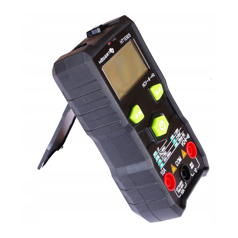
HOGERT HT1E601 User manual

1
Adres producenta/ Adresse des Herstellers/ Manufacturer’s Address/ Адрес производителя
GTV Poland Sp. z o.o. Sp. k., ul. Przejazdowa 21, 05-800 Pruszków
PL
INSTRUKCJA OBSŁUGI
MULTIMETR CYFROWY HT1E601
Dziękujemy za zakup naszego produktu. Wyprodukowany zgodnie z wysokim standardem produkt zapewni lata bezproblemowej pracy
pod warunkiem stosowania zgodnie z instrukcją i odpowiednio utrzymany.
SPIS TREŚCI
1.Opis ogólny
1.1 Informacje dotyczące bezpieczeństwa
1.1.1 Symbole bezpieczeństwa
1.1.2 Środki ochrony
2. Opis przyrządu
2.1 Wygląd urządzenia
2.2 Opis symboli
2.3 Opis przycisków
2.4 Opis gniazd wejściowych
2.5 Zawartość opakowania
3. Instrukcja obsługi
3.1 Regularna obsługa
3.1.1 Blokada odczytu i podświetlenie
3.1.2 Funkcja podświetlenia
3.1.3 Funkcja automatycznego wyłączania
3.2 Przewodnik pomiarowy
3.2.1 Pomiar napięcia przemiennego i stałego
3.2.2 Pomiar rezystancji / pojemności
3.2.3 Pomiar diody wł. / Wył
3.2.4 Pomiar pojemność
3.2.5 Pomiar prądu
3.2.6 Test NCV
3.2.7 Test przewodu neutralnego / pod napięciem
3.2.8 Test baterii
3.2.9 Pomiar SMART
4. Wskaźniki techniczne
4.1 Kompleksowe wskaźniki
4.2 Wskaźniki precyzji
4.2.1 Napięcie stałe
4.2.2 Napięcie przemienne
4.2.3 Oporność
4.2.4 Dioda
4.2.5 Podłączanie / rozłączanie brzęczyka
4.2.6 Pojemność
4.2.7 Prąd stały
4.2.8 Prąd przemienny
4.2.9 Pomiar baterii
5. Wymiana baterii
OCHRONA ŚRODOWISKA
Symbol wskazujący na selektywne zbieranie zużytego sprzętu elektrycznego i elektronicznego. Zużyte urządzenia elek-
tryczne są surowcami wtórnymi – nie wolno wyrzucać ich do pojemników na odpady domowe, ponieważ zawierają sub-
stancje niebezpieczne dla zdrowia ludzkiego i środowiska! Prosimy o aktywną pomoc w oszczędnym gospodarowaniu
zasobami naturalnymi i ochronie środowiska naturalnego przez przekazanie zużytego urządzenia do punktu składowania
zużytych urządzeń elektrycznych. Aby ograniczyć ilość usuwanych odpadów konieczne jest ich ponowne użycie, recykling
lub odzysk w innej formie.

2Adres producenta/ Adresse des Herstellers/ Manufacturer’s Address/ Адрес производителя
GTV Poland Sp. z o.o. Sp. k., ul. Przejazdowa 21, 05-800 Pruszków
1. INFORMACJE OGÓLNE
Urządzenie jest przeznaczone do użytku zarówno w prywatnych gospodarstwach domowych jak i do użytku komercyjnego. Multimetr
cyfrowy to inteligentny, automatyczny zintegrowany ręczny przyrząd (10000 zliczeń) z funkcją TRUE RMS. Posiada alarm bezpieczni-
kowy, alarm nieprawidłowego włożenia wtyków, ochronę przed przeciążeniem oraz wskaźnik spadku napięcia akumulatora i inne
funkcje. Jest to idealne profesjonalne narzędzie wielofunkcyjne. Został zaprojektowany i wyprodukowany zgodnie z wymogami bez-
pieczeństwa dotyczącymi elektronicznego przyrządu pomiarowego i podręcznego multimetru cyfrowego zgodnie z międzynarodową
normą bezpieczeństwa dla elektryków EN 61010. Jest zgodny z 600V CAT. Ⅲ normy EN 61010 i stopień zanieczyszczenia. Przed użyciem
tego urządzenia należy uważnie przeczytać instrukcję obsługi i zwrócić uwagę na powiązane standardy bezpieczeństwa pracy.
Wszelkie inne sposoby użytkowania nie są zamierzone i mogą prowadzić do uszkodzenia mienia lub nawet obrażeń ciała. Urządzenie
należy używać wyłącznie zgodnie z niniejszą instrukcją obsługi. Producent nie ponosi żadnej odpowiedzialności za uszkodzenia spo-
wodowane użytkowaniem niezgodnym z przeznaczeniem. Urządzenie nie jest przyrządem pomiarowym w rozumieniu ustawy “Prawo
o pomiarach”.
OGÓLNE WARUNKI BEZPIECZEŃSTWA
W zakresie właściciela i użytkownika jest przeczytanie, zrozumienie i przestrzeganie poniższych zasad:
WAŻNE: Proszę przeczytać tą instrukcję uważnie. proszę zwrócić szczególną uwagę na wymogi bezpiecznego użytkowania,
ostrzeżenia i uwagi. używać produkt prawidłowo i z uwagą do celów, do których został przeznaczony. nieprzestrzeganie tego
może spowodować uszkodzenie i/lub uszczerbek zdrowia i spowoduje utratę gwarancji. proszę przechowywać instrukcję w
bezpiecznym miejscu w celu dalszego używania. przekazując urządzenie innej osobie, oddaj jej także instrukcję obsługi.
• Proszę wykorzystywać urządzenie jedynie dla celu, jaki został przewidziany dla urządzenia.
• Proszę trzymać urządzenie z daleka od ciepła, bezpośredniego promieniowania słonecznego, wilgoci (w żadnym wypadku nie zanurzać
w substancjach płynnych) oraz ostrych krawędzi. Proszę nie obsługiwać urządzenia wilgotnymi dłońmi.
• Pracującego urządzenia nie należy pozostawiać bez nadzoru. Przed opuszczeniem pomieszczenia urządzenie należy zawsze wyłączyć.
• Należy regularnie sprawdzać, czy urządzenie. W razie uszkodzenia należy przestać korzystać z urządzenia.
• Dla bezpieczeństwa dzieci proszę nie zostawiać swobodnie dostępnych części opakowania (torby plastikowe, kartony, styropian, itp.).
OSTRZEŻENIE
Nie pozwalaj dzieciom bawić się folią. Niebezpieczeństwo uduszenia!
To urządzenie nie jest przeznaczone do użytku przez osoby z ograniczonymi zdolnościami fizycznymi, sensorycznymi lub umysłowymi
lub brakiem doświadczenia i / lub umiejętności, chyba że takim osobom towarzyszą i są nadzorowane przez osoby odpowiedzialne
za ich bezpieczeństwo lub otrzymały precyzyjne instrukcje użytkowania tego urządzenia i zrozumiały wynikające z tego ryzyko. Dzieci
mogą korzystać z tego urządzenia tylko w wieku powyżej 8 i pod nadzorem osoby odpowiedzialnej za ich bezpieczeństwo lub jeśli
otrzymały instrukcje użytkowania tego urządzenia i zrozumiały wynikające z tego ryzyko. Dzieci nie mogą bawić się tym urządzeniem.
1.1.1 SYMBOLE BEZPIECZEŃSTWA:
Wysokie napięcie Uziemienie
AC (prąd zmienny) Podwójna izolacja
DC (prąd stały) Bezpiecznik
Uszkodzony bezpiecznik Zgodny z wytycznymi UE
Ostrzeżenia i ważne znaki bezpieczeństwa można znaleźć w instrukcji obsługi przed użyciem.
Niewłaściwe użycie może spowodować uszkodzenie sprzętu lub jego części.
1.1.2 ŚRODKI OCHRONY
* Podczas pomiaru napięcia wytrzymuje max. napięcie wejściowe wynosi 600 V AC / DC.
* Podczas pomiaru częstotliwości, rezystancji, włączania i wyłączania diody napięcie AC / DC poniżej 600 V może być wytrzymane.
* µ Podczas pomiaru prądu A i prądu mA zabezpieczyć rurką ochronną (F600mA / 250V).
Na przekładniach uA i mA, jeśli bezpiecznik jest zepsuty, po włożeniu wtyczki do Ua /mA na ekranie wyświetli się BEZPIECZNIK
i symbol wskazujący na uszkodzenie bezpiecznika, w takim przypadku należy wymienić bezpiecznik odpowiednia specyfikacja,
aby kontynuować pomiar. To samo wskazanie wyświetli się również przy aktualnym biegu 10 A.

3
Adres producenta/ Adresse des Herstellers/ Manufacturer’s Address/ Адрес производителя
GTV Poland Sp. z o.o. Sp. k., ul. Przejazdowa 21, 05-800 Pruszków
2. OPIS PRZYRZĄDU
2.1 WYGLĄD URZĄDZENIA
1
2
3
6
5
4
7
1. Strefa bezdotykowej indukcji
2. Bezdotykowy wskaźnik napięcia
3. Ekran LCD
4. Podświetlenie
5. Przyciski
6. Przełacznik obrotowy
7. Gniazdo wejściowe
2.2. OPIS SYMBOLI
Symbol Opis
Niski poziom naładowania baterii
Automatyczne wyłączanie
Wysokie napięcie
Odczyt negatywny
AC Wskaźnik prądu przemiennego
DC Wskaźnik prądu stałego
Test właczanie/wyłączanie
Test diod
AUTO Automatyczny zasięg
HPrzechowywanie danych
NCV Bezdotykowe wykrywanie napięcia
przemiennegoNon-contact AC voltage
detection.

4Adres producenta/ Adresse des Herstellers/ Manufacturer’s Address/ Адрес производителя
GTV Poland Sp. z o.o. Sp. k., ul. Przejazdowa 21, 05-800 Pruszków
LIVE Test przewodu pod napięciem
SMART Pomiar w trybie SMART
Uszkodzony bezpiecznik
Fuse Uszkodzony bezpiecznik
V, mV V: V, jednostka napięcia
mV: mV, 1x10⁻³ lub 0.001 V
A, mA, µA A: A, jednostka natężenia
mA: mA, 1x10⁻³ lub 0.001 A
Ω, kΩ, MΩ Ω: Ohm, jednostka oporu
kΩ: kilo-ohm, 1000 ohms
MΩ: Meg-ohm, 1000,000 ohms
mF, µF, nF
F: F, jednostka pojemności
mF: mF, 1x10⁻³or 0.001 F
µF: μF, 1x10⁻⁶ or 0.000001 F
nF: nF, 1x10⁻⁹ lub 0.000000001 F
2.3 FUNKCJE PRZYCISKÓW
Przycisk Opis funkcji
SEL Klawisz wyboru funkcji na przekładni napięciowej AC / DC
HOLD Zapisanie danych
Naciśnij krótko, aby włączyć/ wyłączyć latarkę
2.4 GNIAZDO WEJŚCIOWE
Gniazdo wejściowe Opis
COM Do podłaczenia czarnej wtyczki testowej
V Ω
SMART,
LIVE, mA
Do pojemności, włączenia-wyłączenia, pomiaru diody, napięcia, rezystancji,
trybu inteligentnego i oceny przewodu pod napięciem (podłączony do
czerwonej wtyczki testowej).
10A zacisk wejściowy prądu 10A (podłączony do czerwonej wtyczki testowej
2.5 ZAWAROŚĆ OPAKOWANIA
1. Instrukcja obsługi 1 szt.
2. Przewody testowe 1 para
3. 1.5x2 AAA batterie 2 szt.
3. INSTRUKCJA OBSŁUGI
3.1 REGULARNA OBSŁUGA
3.1.1 Blokada odczytu i podświetlenie
W trybie wstrzymania odczytu bieżący odczyt może zostać zatrzymany na wyświetlaczu. Naciśnij ponownie przycisk HOLD / BL, aby
wyjść z trybu wstrzymania odczytu. Naciśnij długo „HOLD / BL”, aby włączyć podświetlenie, i długo naciśnij „HOLD / BL”, aby wyłączyć
podświetlenie.
3.1.2 Funkcja oświetlenia
1. Naciśnij przycisk „ ”, aby włączyć latarkę
2. Naciśnij ponownie przycisk „ ”, aby wyłączyć latarkę.
3.1.3 Funkcja automatycznego wyłączania
Jeśli w ciągu około 15 minut po uruchomieniu nie zostanie wykonana żadna operacja, urządzenie wyda dźwięk Di-Di w celu
automatycznego wyłączenia zasilania i przejdzie w stan uśpienia. W trybie automatycznego wyłączania naciśnij przycisk SEL,
aby uruchomić ponownie.

5
Adres producenta/ Adresse des Herstellers/ Manufacturer’s Address/ Адрес производителя
GTV Poland Sp. z o.o. Sp. k., ul. Przejazdowa 21, 05-800 Pruszków
3.2 Przewodnik pomiarowy
Podczas pomiaru napięcia lub rezystancji do pomiaru można wybrać zakres automatyczny lub zakres ręczny.
3.2.1 Pomiar napięcia przemiennego i stałego
Aby uniknąć porażenia prądem i /lub uszkodzenia urządzenia nie wolno mierzyć napięcia wyższego niż 600 V
Zakresy napięcia dla prądu przemiennego i stałego (AC/DC) przyrządu wynoszą: 999,9 mV, 9,999 V, 99,99 V i 600 V.
Zmierz napięcie AC lub DC:
1. Przekręć przełącznik obrotowy na ikonę (naciśnij przycisk SEL, aby przełączyć napięcie stałe i przemienne).
2. Podłącz czarny I czerwony wtyk testowy gniazda wejściowego COM i gniazda wejściowego V.
3.2.2 Pomiar rezystancji / pojemności
Aby uniknąć uszkodzenia przyrządu lub mierzonego sprzętu, przed pomiarem rezystancji należy odciąć wszystkie zasilane obwody
i całkowicie rozładować wszystkie kondensatory wysokiego napięcia.
Zmierz opór:
1. Przekręć przełącznik obrotowy na pozycję , aby przejść do trybu pomiaru rezystancji;
2. Podłącz czarny wtyk testowy i czerwony wtyk testowy do gniazda wejściowego COM i gniazda wejściowego V / Ω.
3.2.3 Pomiar diody wł. / wył
Przyrząd przyjmuje funkcję automatycznego rozpoznawania włączania / wyłączania diody.
Przeprowadź pomiar wł/wył lub diody:
1. Przekręć przełącznik obrotowy na pozycję / .
2. Podłącz czarny wtyk testowy i czerwony wtyk testowy do gniazda wejściowego COM i gniazda wejściowego V / Ω.
3.2.4 Pomiar pojemności
Aby uniknąć uszkodzenia przyrządu, przed pomiarem pojemności należy odciąć wszystkie zasilane obwody i całkowicie rozładować
wszystkie kondensatory wysokiego napięcia. Użyj napięcia stałego, aby potwierdzić rozładowanie kondensatora.
1. Przekręć przełącznik obrotowy na pozycję i naciśnij przycisk SEL, aby przejść do trybu pomiaru pojemności.
2. Podłącz czarny wtyk testowy i czerwony wtyk testowy do gniazda wejściowego COM i gniazda wejściowego .
3.2.5 Pomiar natężenia prądu
Gdy napięcie w obwodzie przekracza 250 V, nie należy mierzyć prądu w obwodzie.
1. Ustaw przełącznik obrotowy na mA/A w celu pomiaru natężenia prądu.
2. Podłącz czarny wtyk testowy do gniazda wejściowego COM. Jeśli zmierzony prąd jest mniejszy niż 600 mA, podłącz czerwony
wtyk testowy do gniazda wejściowego uA/mA; jeśli zmierzony prąd wynosi od 600mA do 10A, podłącz czerwony wtyk testowy
do gniazda wejściowego 10A.
Uwaga: Za pomocą przycisku przełączającego SEL można przeprowadzić konwersję prądu przemiennego i stałego (AC/DC).
3.2.6 Test NCV
Naciśnij klawisz NCV i zbliż górną część przyrządu do przewodu, zaświeci odpowiedni wskaźnik natężenia sygnału, gdy indukowane
napięcie jest niskie, --- L wyświetla się na ekranie, i zaświeci się zielony wskaźnik ; gdy indukowane napięcie jest wysokie, --- H
wyświetla się na ekranie, i świecą się dwa czerwone wskaźniki. Brzęczyk wydaje dźwięki alarmowe o innej częstotliwości.
3.2.7 Test przewodu pod napięciem
1. Przekręć przełącznik obrotowy na pozycję napięcia.
2. Podłącz czerwony wtyk testowy do gniazda wejściowego V.
3. Zbliż czarny wtyk do przewodu pod napięciem. Jeśli wykryty przepływ prądu, na ekranie wyświetla się komunikat LIVE,
czerwony wskaźnik jest włączony, a brzęczyk wydaje dźwięk alarmu.
3.2.8 Test baterii lub akumulatorka
1. Przekręć pokrętło na symbol akumulatora.
2. Podłącz czerwony wtyk testowy do gniazda wejściowego V, a czarny wtyk do portu COM.
3.2.9 Pomiar SMART
1. Ustaw przełącznik obrotowy w pozycji SMART, w takim przypadku przyrząd przejdzie w tryb inteligentnego pomiaru.
2. Podłącz czarny wtyk testowy i czerwonywtyk testowy do gniazda wejściowego COM i gniazda wejściowego V/Ω.
3. Przyrząd automatycznie oceni zmierzoną wartość i rodzaj zmierzonego sygnału.
Uwaga: SMART może automatycznie rozpoznać napięcie AC, napięcie DC, rezystancję
6Adres producenta/ Adresse des Herstellers/ Manufacturer’s Address/ Адрес производителя
GTV Poland Sp. z o.o. Sp. k., ul. Przejazdowa 21, 05-800 Pruszków
4. WSKAŹNIKI TECHNICZNE
4.1 Kompleksowe wskaźniki
Warunków środowiskowych: 600V CAT. III
Temperatura i wilgotność środowiska pracy: 0 ~ 40 ° C (<80% RH, <10 °C nieuwzględnione).
Temperatura i wilgotność środowiska przechowywania: -10 ~ 60 ° C (wilgotność względna <70%, akumulator musi być wyjęty).
• Zabezpieczenie bezpiecznikowe: Bezpiecznik FF 600mA/250V; Bezpiecznik przekładniowy FF 10A / 250 V.
• Współczynnik konwersji: około 3 razy/sekundę
• Wyświetlacz: max 9999.
• Wskazanie przekroczenia zakresu: na wyświetlaczu LCD pojawi się „OL”.
• Wskazanie niskiego napięcia akumulatora:
Gdy napięcie akumulatora jest niższe niż normalne napięcie robocze, wyświetli się „ ”.
• Wskazanie polaryzacji wejściowej: automatycznie wyświetli się „–”.
• Zasilanie: 2 x bateria AAA 1,5 V.
• Wymiary: 150 x 70 x 50 mm
• Waga: 195 g
4.2 Wskaźniki precyzji
Warunki podstawowe: temperatura otoczenia wynosi od 18 ° C do 28 ° C, a wilgotność względna nie przekracza 80 ° C.
4.2.1 Napięcie stałe
Zakres Rozdzielczość Dokładność
10 V 1 mV
±(0.5% odczytu + 3 znaki)100 V 10 mV
600 V 100 mV
(SMART) Napięcie prądu stałego
Zakres Rozdzielczość Dokładność
600 V 0.1 V ±(0.5% odczytu + 4 znaki)
Impedancja wejściowa: 10 MΩ
Max. napięcie wejściowe: 600 V, min. napięcie pomiarowe 0,5 V DC
4.2.2 Napięcie przemienne
Zakres Rozdzielczość Dokładność
10 V 0.1 mV ±(0.8% odczytu + 3 znaki)
100 V 1 mV
600 V 100 mV ±(1% odczytu + 5 znaków)
(SMART) Napięcie prądu przemiennego
Zakres Rozdzielczość Dokładność
600 V 0.1 V ±(3.0% odczytu + 7 znaków)
Impedancja wejściowa: 10 MΩ
Max. napięcie wejściowe: 600 V
Pasmo przenoszenia: 50 Hz-400 Hz RMS

7
Adres producenta/ Adresse des Herstellers/ Manufacturer’s Address/ Адрес производителя
GTV Poland Sp. z o.o. Sp. k., ul. Przejazdowa 21, 05-800 Pruszków
4.2.3 Automatyczny pomiar oporności
Zakres Rozdzielczość Dokładność
1000 Ω 0.1 Ω
±(0.8% odczytu + 3 znaki)
10 kΩ 1 Ω
100 kΩ 10 Ω
1000 kΩ 100 Ω
10 MΩ 1 kΩ
100 MΩ 10 kΩ ±(1.5% odczytu + 10 znaków)
(SMART) oporność
Zakres Rozdzielczość Dokładność
6 kΩ 0.1 Ω ±(1.2% odczytu + 5 znaków)
Zabezpieczenie przed przeciążeniem: 250 V.
Napięcie biegu jałowego: 1,5 V.
4.2.4 Test diody
Fukncja Zakres Rozdzielczość Warunki testu
Diode test
0.15V-2.5V 0.001V
Prąd stałego: około 1 mA; napięcie
w obwodzie otwartym: około 2,5 V.
Wyświetlacz pokazuje przybliżoną
wartość spadku napięcia diody.
Zabezpieczenie przed przeciążeniem: 250 V.
4.2.5 Brzęczyk włączanie/wyłączanie
Funkcja Zakres Rozdzielczość Wprowadzenie Warunki testu
100 Ω 1 Ω Rezystancja nie jest większa niż
30 Ω, a wbudowany brzęczyk
wydaje ciągły dźwięk.
Napięcie w obwodzie
otwartym: około 1 V.
Zabezpieczenie przed przeciążeniem: 250 V.
4.2.6 Pojemność
Zakres Rozdzielczość Dokładność
100 nF 0.01 nF
±(3.5% odczytu + 15 znaków)
1000 nF 0.1 nF
10 µF 1 nF
100 µF 10 nF
1000 µF 100 nF
10 mF 1 uF
Zabezpieczenie przed przeciążeniem: 250 V.
4.2.7 Prąd stały
Zakres Rozdzielczość Dokładność
600 mA 0.1 mA ±(0.8% odczytu + 3 znaki)
10 A 10 mA ±(1.2% odczytu + 3 znaki)
Zabezpieczenie przed przeciążeniem: bezpiecznik zakresu mA (FF630mA / 250V); Bezpiecznik topikowy 10A (FF10A / 250V).
Gdy zmierzony prąd jest większy niż 5A, ciągły czas pomiaru nie może przekroczyć 15 sekund i konieczne jest zatrzymanie
pomiaru prądu na 1 minutę po pomiarze.

8Adres producenta/ Adresse des Herstellers/ Manufacturer’s Address/ Адрес производителя
GTV Poland Sp. z o.o. Sp. k., ul. Przejazdowa 21, 05-800 Pruszków
4.2.8 Prąd przemienny
Zakres Rozdzielczość Dokładność
600 mA 0.1 mA ±(1% odczytu + 3 znaki)
10 A 10 mA ±(1.5% odczytu + 3 znaki)
Zabezpieczenie przed przeciążeniem: bezpiecznik zakresu mA (FF630mA / 250V); Bezpiecznik topikowy 10A (FF10A / 250V).
Gdy zmierzony prąd jest większy niż 5A, ciągły czas pomiaru nie może przekroczyć 15 sekund i konieczne jest zatrzymanie
pomiaru prądu na 1 minutę po pomiarze. Pasmo przenoszenia: 50 Hz - 400 Hz, RMS
4.2. 9. Pomiar baterii
Zakres Rozdzielczość
1.5 V 0.001 V
9 V 0.001 V
Zabezpieczenie przed przeciążeniem: 250 V DC / AC
5. Wymiana baterii
Aby uniknąć porażenia prądem lub obrażeń ciała spowodowanych błędnym odczytem, należy natychmiast wymienić
baterię, gdy na wyświetlaczu przyrządu pojawi się symbol „ ”. Przed otwarciem pokrywy baterii i wymianą baterii
konieczne jest wyłączenie i sprawdzenie, czy testery zostały odłączone od mierzonego obwodu.
Wymień baterię zgodnie z następującymi krokami:
1. Odłącz zasilanie instrumentu.
2. Wyciągnij wszystkie wtyczki testowe z gniazda wejściowego.
3. Odkręć śruby mocujące pokrywę baterii.
4. Zdejmij pokrywę baterii.
5. Wyjmij starą baterię.
6. Wymień na nową baterię AAA 2 x 1,5 V.
7. Umieść pokrywę baterii i dokręć śruby.

9
Adres producenta/ Adresse des Herstellers/ Manufacturer’s Address/ Адрес производителя
GTV Poland Sp. z o.o. Sp. k., ul. Przejazdowa 21, 05-800 Pruszków
EN
USER’S MANUAL
DIGITAL MULTIMETER HT1E601
Thank you for purchasing our product. Manufactured to a high standard, this product will, if used according to these instructions, and
properly maintained, give you years of trouble free performance.
TABLE OF CONTENTS
1.General
1. General description
1.1 Safety information
1.1.1 Safety symbols
1.1.2 Safety measures
2. Device description
2.1 Device appearance
2.2 Description of symbols
2.3 Description of buttons
2.4 Input sockets description
2.5 Package content
3. User’s manual
3.1 Regular operation
3.1.1 Readout lock and backlighting
3.1.2 Backlight function
3.1.3 Automatic shutdown function
3.2 Measuring guide
3.2.1 Measurement of AC and DC voltage
3.2.2 Resistance / capacitance measurement
3.2.3 Diode on/off measurement
3.2.4 Capacitance measurement
3.2.5 Current measurement
3.2.6 NCV test
3.2.7 Neutral / live wire test
3.2.8 Battery test
3.2.9 SMART measurement
4. Technical indicators
4.1 Comprehensive indicators
4.2 Precision indicators
4.2.1 Fixed voltage
4.2.2 Alternating voltage
4.2.3 Resistance
4.2.4 Diode
4.2.5 Connecting / disconnecting the buzzer
4.2.6 Capacitance
4.2.7 Direct Current
4.2.8 Alternating current
4.2.9 Battery measurement
5. Battery replacement
ENVIRONMENTAL PROTECTION
Symbol indicating separate collection of electrical and electronic equipment waste. Used electrical appliances are secon-
dary raw materials - they must not be disposed of in household waste, as they contain substances hazardous to human
health and the environment! Please actively help us to manage natural resources and protect the environment by handing
over used equipment to the waste electrical equipment storage point. To reduce the amount of waste disposed of, it is
necessary to reuse, recycle or recover them in another form.

10 Adres producenta/ Adresse des Herstellers/ Manufacturer’s Address/ Адрес производителя
GTV Poland Sp. z o.o. Sp. k., ul. Przejazdowa 21, 05-800 Pruszków
1. GENERAL INFORMATION
The device is intended for use both in private households and for commercial purposes. The digital multimeter is an intelligent, au-
tomatic integrated handheld device (10000 counts) with TRUE RMS function. It has a fuse alarm, an incorrect plug insertion alarm,
overload protection, battery voltage drop indicator and other functions. It is the ideal professional multitool. It was designed and ma-
nufactured in accordance with the safety requirements for an electronic measuring instrument and a hand-held digital multimeter in
accordance with the international safety standard for electricians EN 61010. It’s compatible with 600V CAT. Ⅲ EN 61010 and contamina-
tion level. Before using this device, read the user’s manual carefully and pay attention to the associated safety standards.
Any other use is not intended and may lead to property damage or even personal injury. Use the device only in accordance with this
manual. The manufacturer does not assume any liability for damage caused by improper use. The device is not a measuring device
within the meaning of the „Measurement Law”.
GENERAL SAFETY CONDITIONS
It is within the scope of the owner and user’s responsibility to read, understand and follow these rules:
IMPORTANT: Please read this manual carefully. Please pay special attention to the requirements of safe use, warnings and
notices. Use the product correctly and carefully for the purposes for which it is intended. Failure to do so may result in da-
mage and/or harm to health and will void the warranty. Please keep this manual in a safe place for further use. When pas-
sing the device on to another person, also give them the manual.
• Please use the device only for the purpose intended for the device.
• Please keep the device away from heat, direct sunlight, moisture (under no circumstances immerse in liquid substances) and sharp
edges. Do not operate the device with wet hands.
• Do not leave the device running unattended. Always switch off the unit before leaving the room.
• Check the device regularly. In case of damage, stop using the device.
• For the safety of children, please do not leave any freely accessible parts of the packaging (plastic bags, cartons, polystyrene, etc.).
WARNING
Don’t let the kids play with the foil. Danger of suffocation!
This device is not intended for use by persons with reduced physical, sensory or mental capabilities or lack of experience and/or skills,
unless such persons are accompanied and supervised by persons responsible for their safety or have received precise instructions
for the device usage and understand the risks involved. Children may only use this device if they are over 8 years old and under the
supervision of a person responsible for their safety or if they have received instructions for use of this device and understand the risks
involved. Children cannot play with this device.
1.1 SAFETY SYMBOLS:
High voltage Ground
Alternating current Double insulation
Direct current Fuse
Defective fuse Compliant with EU instructions
Warnings and important safety signs can be found in the manual before use. Improper use may damage
the equipment or its parts.
1.2 PROTECTION MEASURES
* When measuring the voltage, the maximum input voltage is 600 V AC / DC.
* When measuring frequency, resistance, switching on and off the diode, a voltage of AC/DC below 600 V can be resisted.
* µ When measuring the current A and mA, secure with a protective tube (F600mA / 250V).
On the gearboxes uA and mA, if the fuse is broken, after inserting the plug into the Ua /mA, the SAFETY and the symbol
indicating a fuse failure, in this case the fuse must be replaced with the appropriate specification in order to continue measuring.
The same indication will also be displayed for the current 10A run.

11
Adres producenta/ Adresse des Herstellers/ Manufacturer’s Address/ Адрес производителя
GTV Poland Sp. z o.o. Sp. k., ul. Przejazdowa 21, 05-800 Pruszków
2. DESCRIPTION OF THE DEVICE
2.1 THE APPEARANCE OF THE DEVICE
1
2
3
6
5
4
7
1. Non-contact induction zone
2. Non-contact voltage indicator
3. LCD screen
4. Backlighting
5. Buttons
6. Rotary switch
7. Entrance socket
2.2. DESCRIPTION OF SYMBOLS
Symbol Introduction
Low battery
Automatic shutdown
High voltage
Negative readout
AC AC Indicator
DC DC Indicator
On/Off test
Diode test
AUTO Automatic range
HData storage
NCV Non-contact AC voltage detection.

12 Adres producenta/ Adresse des Herstellers/ Manufacturer’s Address/ Адрес производителя
GTV Poland Sp. z o.o. Sp. k., ul. Przejazdowa 21, 05-800 Pruszków
LIVE Testing the live wire
SMART Measurement in SMART mode
Defective fuse
Fuse Defective fuse
V, mV V: V, Voltage unit
mV: mV, 1x10⁻³ or 0.001 V
A, mA, µA A: A, intensity unit
mA: mA, 1x10⁻³ or 0.001 A
Ω, kΩ, MΩ Ω: Ohm, resistance unit
kΩ: kilo-ohm, 1000 ohms
MΩ: Meg-ohm, 1000,000 ohms
mF, µF, nF
F: F, capacity unit
mF: mF, 1x10⁻³or 0.001 F
µF: μF, 1x10⁻⁶ or 0.000001 F
nF: nF, 1x10⁻⁹ lub 0.000000001 F
2.3 BUTTON FUNCTIONS
Button Description of functions
SEL Function selection buttons on AC/DC voltage gearbox
HOLD Saving data
Press briefly to turn the flashlight on/off
2.4 ENTRANCE SOCKET
Entrance socket Description
COM For connecting the black test plug
V Ω
SMART,
LIVE, mA
For capacitance, on-off, diode measurement, voltage, resistance, intelligent
mode and evaluation of a live wire (connected to a red test plug).
10A 10A current input terminal (connected to red test plug
2.5 PACKAGE CONTENTS
1. User’s manual 1 item
2. Test wires 1 pair
3. 1.5x2 AAA batteries 2 items
3. USER’S MANUAL
3.1 REGULAR SERVICE
3.1.1 Readout lock and backlight
In the read pause mode, the current reading can be stopped on the display. Press the HOLD / BL button again to exit the read pause
mode. Press „HOLD / BL” long to turn on the backlight, and press „HOLD / BL” long to turn off the backlight.
3.1 2 Lighting function
1. Press the button „ ”, to turn on the flashlight
2. Press the button again „ „ to turn off the flashlight.
3.1 3 Automatic shutdown function
If no operation is performed within approximately 15 minutes after start-up, the unit will emit a Di-Di sound to automatically turn
off the power and go to sleep mode. In auto shutdown mode, press the SEL button to restart.
3.2 Measuring guide
When measuring voltage or resistance, the automatic or manual range can be selected.

13
Adres producenta/ Adresse des Herstellers/ Manufacturer’s Address/ Адрес производителя
GTV Poland Sp. z o.o. Sp. k., ul. Przejazdowa 21, 05-800 Pruszków
3.2.1 Measurement of AC and DC voltage
To avoid electric shock and/or damage to the unit do not measure over 600 V.
The voltage ranges for AC and DC (AC/DC) of the device are: 999.9 mV, 9.999 V, 99.99 V and 600 V.
Measure the AC or DC voltage:
1. Turn the rotary switch to the icon (press the SEL button to switch between DC and AC voltage).
2. Connect the black and red test plug of the COM input socket and the V input socket.
3.2.2 Resistance / capacitance measurement
To avoid damage to the device or the equipment being measured, all powered circuits should be cut off and all high voltage capacitors
should be completely discharged before resistance measurement.
Measure the resistance:
1. Turn the rotary switch to position , to switch to resistance measurement mode;
2. Connect the black test plug and the red test plug to the COM input socket and the V / Ω.
3.2.3 On/Off diode measurement
The device adopts the function of automatic diode on/off recognition.
Perform on/off or diode measurement:
1. Turn the rotary switch to the position / .
2. Connect the black test plug and the red test plug to the COM input socket and the V / Ω.
3.2 4. Capacitance measurement
To avoid damage to the instrument, all powered circuits should be cut off and all high voltage capacitors should be completely di-
scharged before the capacity measurement. Use DC voltage to confirm discharge of the capacitor.
1. Turn the rotary switch to the position and press the SEL button to enter capacity measurement mode.
2. Connect the black test plug and the red test plug to the COM and input sockets .
3.2 5. Current measurement
When the voltage in the circuit exceeds 250 V, do not measure the current in the circuit.
1. Set the rotary switch to mA/A to measure the current.
2. Connect the black test plug to the COM input socket. If the measured current is less than 600mA, plug the red test plug into
the uA/mA input socket; if the measured current is between 600mA and 10A, plug the red test plug into the 10A input socket.
Note: The SEL switching button can be used to carry out the AC/DC conversion.
3.2 6. NCV test
Press the NCV key and close the top of the instrument to the wire, the corresponding signal strength indicator lights up when induced
low voltage, --- L is displayed on the screen, and the green indicator lights up when induced high voltage, --- H is displayed on the
screen, and two red indicators light up. The buzzer sounds an alarm at a different frequency.
3.2 7. Testing the live wire
1. Turn the rotary switch to the voltage position.
2. Connect the red test plug to the V input socket.
3. Close the black plug to the live wire. If a current flow is detected, the screen displays LIVE, the red indicator is on and the
buzzer sounds an alarm.
3.2 8. Battery or rechargeable battery test
1. Turn the knob to the battery symbol.
2. Connect the red test plug to the V input socket and the black plug to the COM port.
3.2 9. SMART measurement
1. Set the rotary switch to the SMART position, in this case the instrument will go into smart measurement mode.
2. Connect the black test plug and the red test plug to the COM input socket and the V/Ⅲinput socket.
3. The device will automatically evaluate the measured value and the type of signal measured.
Note: SMART can automatically recognize AC voltage, DC voltage, resistance
4 TECHNICAL INDICATORS
4.1 Comprehensive indicators of environmental conditions:
600V CAT. III
Temperature and humidity of the working environment: 0 ~ 40 °C (<80% RH, <10 °C not accounted for).
Temperature and humidity of the storage environment: -10 ~ 60°C (relative humidity <70%, battery must be removed).
• Fuse protection: Fuse FF 600mA/250V; Gearbox fuse FF 10A / 250 V.
• Conversion factor: approximately 3 times/second

14 Adres producenta/ Adresse des Herstellers/ Manufacturer’s Address/ Адрес производителя
GTV Poland Sp. z o.o. Sp. k., ul. Przejazdowa 21, 05-800 Pruszków
• Display: max 9999.
• Overrange indication: the LCD display shows „OL”.
• Low battery voltage indication: When the battery voltage is lower than normal operating voltage, „ „ will be displayed.
• Input polarity indication: „–” will be displayed automatically
• Power supply: 2 x 1.5 V AAA battery.
• Dimensions: 150 x 70 x 50 mm
• Weight: 195 g
4.2 Precision indicators
Basic conditions: ambient temperature is from 18 ° C to 28 ° C and relative humidity does not exceed 80 ° C.
4.2.1 DC voltage
Range Resolution Accuracy
10 V 1 mV
±(0.5% reading + 3 digits)100 V 10 mV
600 V 100 mV
(SMART) DC voltage
Range Resolution Accuracy
600 V 0.1 V ±(0.5% reading + 4 digits)
Input impedance: 10 MΩ
Max. input voltage: 600 V, min. measuring voltage 0.5 V DC
4.2. 2 Alternating voltage
Range Resolution Accuracy
10 V 0.1 mV ±(0.8% reading + 3 digits)
100 V 1 mV
600.0 V 100 mV ± (1% reading + 5 digits)
(SMART) Alternating current voltage
Range Resolution Accuracy
600 V 0.1 V ± (3.0% reading + 7 digits)
Input impedance: 10 MΩ
Max. input voltage: 600 V
Band: 50 Hz-400 Hz RMS

15
Adres producenta/ Adresse des Herstellers/ Manufacturer’s Address/ Адрес производителя
GTV Poland Sp. z o.o. Sp. k., ul. Przejazdowa 21, 05-800 Pruszków
4.2. 3. Automatic resistance measurement
Range Resolution Accuracy
1000 Ω 0.1 Ω
±(0.8% reading + 3 digits)
10 kΩ 1 Ω
100 kΩ 10 Ω
1000 kΩ 100 Ω
10 MΩ 1 kΩ
100 MΩ 10 kΩ ± (1.5% reading +10 digits)
(SMART) resistance
Range Resolution Accuracy
6 kΩ 0.1 Ω ± (1.2% reading + 5 digits)
Overload protection: 250 V.
Idle voltage: 1.5 V.
4.2. 4. Diode test
Function Range Resolution Test conditions
Diode test
0.15V-2.5V 0.001V
Direct current: about 1 mA; voltage in
open circuit: about 2.5 V.
The display shows the approximate
value of the diode voltage drop.
Overload protection: 250 V
4.2. 5 On/Off buzzer
Function range Resolution Introduction Test conditions
100 Ω 1 Ω The resistance is not greater than
30Ⅲand the built-in buzzer
produces a continuous sound.
The voltage in an open
circuit is about 1 V.
Overload protection: 250 V.
4.2. 6. Capacitance
Range Resolution Accuracy
100 nF 0.01 nF
± (3.5% reading + 15 digits)
1000 nF 0.1 nF
10 µF 1 nF
100 µF 10 nF
1000 µF 100 nF
10 mF 1 uF
Overload protection: 250V
4.2. 7. Direct current
Range Resolution Accuracy
600mA 0.1mA ±(0.8% reading + 3 digits)
10.00A 10mA ±(1.2% reading + 3 digits)
Overload protection: mA range fuse (FF630mA / 250V); 10A fuse (FF10A / 250V).
When the measured current is greater than 5A, the continuous measurement time must not exceed 15 seconds and it is neces-
sary to stop the current measurement for 1 minute after the measurement

16 Adres producenta/ Adresse des Herstellers/ Manufacturer’s Address/ Адрес производителя
GTV Poland Sp. z o.o. Sp. k., ul. Przejazdowa 21, 05-800 Pruszków
4.2. 8. Alternating current
Range Resolution Accuracy
600 mA 0.1 mA ±(1% reading + 3 digits)
10 A 10 mA ±(1.5% reading + 3 digits)
Overload protection: mA range fuse (FF630mA / 250V); 10A fuse (FF10A / 250V).
When the measured current is greater than 5A, the continuous measurement time must not exceed 15 seconds and it is neces-
sary to stop the current measurement for 1 minute after the measurement.
Band: 50 Hz - 400 Hz, RMS
4.2. 9. Battery measurement
Range Resolution
1.5 V 0.001 V
9 V 0.001 V
Overload protection: 250 V DC / AC
5. Battery replacement
To avoid electric shock or injury caused by an incorrect reading, replace the battery immediately when the instrument
display shows the „ ”. Before opening the battery cover and replacing the batteries, it is necessary to switch off and
check whether the testers have been disconnected from the circuit being measured.
Replace the battery according to the following steps:
1. Disconnect the power supply to the instrument.
2. Pull all test plugs out of the input socket.
3. Loosen the screws securing the battery cover.
4. Remove battery cover.
5. Remove old battery.
6. Replace with a new AAA 2 x 1.5 V battery.
7. Place the battery cover and tighten the screws.

17
Adres producenta/ Adresse des Herstellers/ Manufacturer’s Address/ Адрес производителя
GTV Poland Sp. z o.o. Sp. k., ul. Przejazdowa 21, 05-800 Pruszków
DE
BENUTZERHANDBUCH
DIGITALESMULTIMETER HT1E601
Vielen Dank, dass Sie sich für unser Produkt entschieden haben.
Hergestellt nach hohen Standard, wird dieses Produkt, wenn den Anweisungen entsprechend verwendet,
und ordnungsgemäß gewartet, Ihnen störungsfreien Betrieb garantieren.
INHALTSVERZEICHNIS
1. Allgemeine Beschreibung
1.1 Sicherheitsinformationen
1.1.1 Sicherheitssymbole
1.1.2 Schutzmaßnahmen
2. Beschreibung
2.1 Geräteanzeige
2.2 Beschreibung der Symbole
2.3 Beschreibung der Tasten
2.4 Beschreibung der Eingangsanschlüsse
2.5 Inhalt der Packung
3. Benutzerhandbuch
3.1 Regelmäßiger Service
3.1.1 Schloss und Hintergrundbeleuchtung lesen
3.1.2 Hintergrundbeleuchtung
3.1.3 Automatische Ausschaltfunktion
3.2 Messanleitung
3.2.1 Messung von Wechsel- und Gleichspannung
3.2.2 Messung von Widerstand / Kapazität
3.2.3 LED-Messung ein / aus
3.2.4 Kapazitätsmessung
3.2.5 Strommessung
3.2.6 NCV-Test
3.2.7 Neutral- / Live-Test
3.2.8 Batterietest
3.2.9 SMART-Messung
4. Technische Indikatoren
4.1 Umfassende Indikatoren
4.2 Präzisionsindikatoren
4.2.1 Gleichspannung
4.2.2 Wechselspannung
4.2.3 Widerstand
4.2.4 Diode
4.2.5 Anschließen / Trennen des Summers
4.2.6 Kapazität
4.2.7 Gleichstrom
4.2.8 Wechselstrom
4.2.9 Batteriemessung
5. Batterie austauschen
UMWELTSCHUTZ
Symbol für die selektive Sammlung von Elektro- und Elektronikaltgeräten. Gebrauchte Elektrogeräte sind recycelbare
Materialien - sie dürfen nicht im Hausmüll entsorgt werden, da sie Substanzen enthalten, die für die menschliche Gesun-
dheit und die Umwelt gefährlich sind! Bitte helfen Sie aktiv beim sparsamen Umgang mit natürlichen Ressourcen und
beim Umweltschutz, indem Sie das gebrauchte Gerät an einen vorgesehenen Sammelpunkt für gebrauchte elektrische
Geräte übergeben. Um die Menge des Abfalls zu verringern ist es notwendig, Elektromüll zu recyclen oder in anderen
Form wiederzuverwerten

18 Adres producenta/ Adresse des Herstellers/ Manufacturer’s Address/ Адрес производителя
GTV Poland Sp. z o.o. Sp. k., ul. Przejazdowa 21, 05-800 Pruszków
1. ALLGEMEINE INFORMATION
Das Gerät ist sowohl für den privaten Gebrauch als auch für den gewerblichen Gebrauch bestimmt. Das Digitalmultimeter ist ein intel-
ligentes und vollautomatisches Gerät, welches über TRUE RMS-Funktion verfügt. Des Weiteren verfügt das Gerät über verschiedene
Schutzfunktionen wie Alarmfunktion bei zu hohen Spannungen, falscher Benutzung, etc.
Das Gerät ist ein multifunktionales und professionelles Werkzeug und wurde gemäß den Sicherheitsanforderungen für das elek-
tronische Messgerät und das digitale Handmultimeter entwickelt und hergestellt, gemäß der internationalen Sicherheitsnorm für
Elektriker EN 61010. Es entspricht 600 V CAT. III EN 61010 Normen und Verschmutzungsgrad. Lesen Sie vor der Verwendung dieses
Geräts die Bedienungsanleitung sorgfältig durch.
Eine nicht für das Gerät vorhergesehene Verwendungen des Geräts kann zu Sachschäden oder sogar zu Verletzungen führen. Ver-
wenden Sie das Gerät nur gemäß dieser Bedienungsanleitung. Der Hersteller übernimmt keine Haftung für Schäden, die durch
unsachgemäße Verwendung verursacht wurden. Das Gerät ist kein Messgerät im Sinne des Eich- und Messgesetzes.
ALLGEMEINE SICHERHEITSBEDINGUNGEN
Beim Besitzer und Benutzer liegt die Pflicht, die nachstehenden Regeln zu lesen, zu verstehen und einzuhalten:
WICHTIG: Bitte lesen Sie die vorliegende Anleitung aufmerksam durch, achten Sie dabei besonders auf die Sicherheitsanfor-
derungen für den Gebrauch, Warnungen und Hinweise. Verwenden Sie das Produkt korrekt und unter Beachtung seines Ver-
wendungszwecks. Die fehlende Einhaltung des Obigen kann zu Sach- oder Gesundheitsschäden führen, und verursacht den
Verlust der Garantie. Bewahren Sie die Bedienungsanleitung bitte an einem sicheren Ort für die weitere Verwendung auf. Bei
der Übergabe des Geräts an eine andere Person sollten Sie dieser auch die Bedienungsanleitung übergeben.
Verwenden Sie das Gerät bitte ausschließlich zu dem Zweck, zu dem es ausgelegt wurde.
Halten Sie das Gerät fern von Wärmequellen, direkter Sonneneinstrahlung, Feuchtigkeit (keinesfalls in flüssige Stoffe eintauchen) sowie
von scharfen Kanten. Gerät nicht mit feuchten Händen bedienen.
Eingeschaltetes Gerät nicht unbeaufsichtigt lassen. Vor dem Verlassen des Raums ist das Gerät immer auszuschalten.
Überprüfen Sie regelmäßig, ob das Gerät nicht beschädigt ist. Im Fall einer Beschädigung ist die Nutzung des Geräts zu unterbrechen.
Im Hinblick auf die Sicherheit von Kindern sollten keine Verpackungsteile (Plastikbeutel, Kartons, Styropor etc.) frei zugänglich liegen
gelassen werden.
WARNUNG
Lassen Sie Kinder nicht mit Folie spielen. Erstickungsgefahr!
Dieses Gerät ist nicht für Personen mit eingeschränkten körperlichen, sensorischen oder geistigen Fähigkeiten oder mangelnder
Erfahrung und / oder Fähigkeiten vorgesehen, es sei denn, diese Personen werden von Personen begleitet und beaufsichtigt, die
für ihre Sicherheit verantwortlich sind, oder sie haben genaue Anweisungen zur Verwendung dieses Geräts erhalten und sind des
Risikos bewusst. Kinder dürfen dieses Gerät nur über 8 Jahre und unter Aufsicht einer für ihre Sicherheit verantwortlichen Person
verwenden oder wenn sie Anweisungen zur Verwendung dieses Geräts erhalten haben und die Risiken verstehen. Kinder dürfen mit
diesem Gerät nicht spielen.
1.1 SICHERHEITSSYMBOLE
Hochspannung Erdung
Wechselspannung Schutzisolierung
Gleichstrom Sicherung
Beschädigte Sicherung Entspricht den EU-Richtlinien
Warnhinweise und wichtige Sicherheitszeichen finden Sie in der Bedienungsanleitung. Bei unsachgemäßer Ver-
wendung kann das Geräte oder einzelne Teile beschädigt werden.
1.2 SCHUTZMASSNAHMEN
• Während der Spannungsmessung hält es max. Die Eingangsspannung beträgt 600 V AC / DC.
• Beim Messen von Frequenz, Widerstand, Ein- und Ausschalten der Diode kann eine AC / DC-Spannung unter 600 V aushalten.
• Bei der Messung von Strom A und mA mit einem Schutzrohr (F600mA / 250V) schützen.
• Wenn die Sicherung defekt ist, wird nach dem Einstecken in den Ua / mA Messanschluss, „SICHERUNG“ und das entsprechende
Symbol auf dem Bildschirm angezeigt. In diesem Fall sollte die Sicherung ersetzt werden, Bevor die Messung fortgesetzt
wird.

19
Adres producenta/ Adresse des Herstellers/ Manufacturer’s Address/ Адрес производителя
GTV Poland Sp. z o.o. Sp. k., ul. Przejazdowa 21, 05-800 Pruszków
2. BESCHREIBUNG
2.1 PRODUKTBESCHREIBUNG
1
2
3
6
5
4
7
1. Induktionszone.
2. Spannungsanzeige.
3. Bildschirm.
4. Hintergrundbeleuchtung.
5. Tasten.
6. Drehschalter.
7. Messanschluss
2.2 SYMBOLBEDEUTUNG
Symbol Bedeutung
Niedriger Batteriestatus
Automatisches Ausschalten
Hochspannung
Negative Messung
AC Wechselspannung-Anzeige
DC Gleichstrom-Anzeige
Ein- / Ausschalt-Test
Dioden-Test
AUTO Automatischer Messbereich
HDatenspeicher

20 Adres producenta/ Adresse des Herstellers/ Manufacturer’s Address/ Адрес производителя
GTV Poland Sp. z o.o. Sp. k., ul. Przejazdowa 21, 05-800 Pruszków
NCV Kontaktlose Wechselspannungserken-
nung.
LIVE Live-Test: Leitungen unter Spannung
SMART Messung im SMART-Modus
Defekte Sicherung
Fuse Defekte Sicherung
V, mV V: V, Spannungseinheit
mV: mV, 1x10⁻³ oder 0.001 V
A, mA, µA A: A, Intensitätseinheit
mA: mA, 1x10⁻³ oder 0.001 A
Ω, kΩ, MΩ Ω: Ohm, Widerstandseinheit
kΩ: kilo-ohm, 1000 ohms
MΩ: Meg-ohm, 1000,000 ohms
mF, µF, nF
F: F, Kapazitätseinheit
mF: mF, 1x10⁻³ oder 0.001 F
µF: μF, 1x10⁻⁶ oder 0.000001 F
nF: nF, 1x10⁻⁹ oder 0.000000001 F
2.3 TASTENBELEGUNG
Taste Beschreibung
SEL Funktionsauswahltaste Spannungsverhältnis AC / DC
HOLD Datenspeicherung
Ein- und Ausschalten der Lampe
2.4 MESSANSCHLUSS
Messanschluss Beschreibung
COM Zum Anschließen der schwarzen Messleitung
V Ω
SMART,
LIVE, mA
Für Kapazität, Ein-Aus, Diodenmessung, Spannung, Widerstand, intelligen-
ten Modus und Live-Wire-Auswertung (rote Messleitung)
10A 10A Stromeingangsanschluss (rote Messleitung)
2.5 VERPACKUNGSINHALT
1. Bedienungsanleitung 1 Stk.
2. Messleitungen 1 Paar
3. 1,5 V Batterie 2 Stk.
3. BEDIENUNGSANLEITUNG
3.1 GEBRAUCH
3.1.1 HOLD MODE und Hintergrundbeleuchtung
Im Hold-Modus kann der aktuelle Messwert auf dem Display dauerhaft angezeigt werden.
Drücken Sie die HOLD / BL-Taste erneut, um den Modus zu verlassen.
Halten Sie die HOLD / BL-Taste lange gedrückt und die Hintergrundbeleuchtung ein- und auszuschalten.
3.1.2 Taschenlampenfunktion
Drücken Sie die Taste „ “ um die Lampe ein- oder auszuschalten
3.1.3 Automatische Ausschaltfunktion
Wenn nach dem Start ca. 15 Minuten lang keine Operation durchgeführt wird, gibt das Gerät ein akustisches Signal von sich und
wechselt automatisch in den Ruhemodus. Drücken Sie SEL-Taste, um das Gerät neu zu starten.
Table of contents
Languages:
Other HOGERT Multimeter manuals

HOGERT
HOGERT HT1E621 User manual

HOGERT
HOGERT HT1E602 User manual

HOGERT
HOGERT HT1E615 AUTO-SMART User manual

HOGERT
HOGERT HT1E630 User manual

HOGERT
HOGERT HT1E604 User manual

HOGERT
HOGERT HT1E600 User manual

HOGERT
HOGERT HT1E620 User manual

HOGERT
HOGERT HT1E605 User manual

HOGERT
HOGERT HT1E606 User manual

HOGERT
HOGERT HT1E603 User manual