Hohner ST 55 L User manual

Hohner Maschinenbau GmbH
Gänsäcker 19, 78532 Tuttlingen, Telefon 07462/9468-0, Telefax 07462/9468-20
Operating-Instructions Page 1
Spare parts list E1
ST 55 L
Edition 04/2010
Stitching Head

ST 55 L Hohner Maschinenbau GmbH
2

Hohner Maschinenbau GmbH ST 55 L 3
Customer Entries
Stitching head no: ...........................
Machine manufacturer: ...........................
Type of manufacturer: ...........................
Manufacturer' s Address
Company name: Hohner Maschinenbau GmbH
Street: Gänsäcker 19
Town: D-78532 Tuttlingen
Telephone: +49 (0) 7462 / 9468-0
Fax: +49 (0) 7462 / 9468-20
Internet: http://www.hohner-postpress.com
Operating-Instructions
Document: Translation of the German
original Operating-Instructions
Version: 04/2010
Spare Parts / Customer Service
Service telephone no: +49 (0) 7462 / 9468-23

List of Contents
ST 55 L Hohner Maschinenbau GmbH
4
List of Contents
1 SAFETY INFORMATION 6
1.1 Purpose of this document .............................................................................................. 6
1.2 The operator .................................................................................................................. 6
1.3 Safety symbols and the displays that have been used .................................................. 6
1.4 Obligation and liability .................................................................................................... 7
1.5 Correct use .................................................................................................................... 7
1.6 Organisational measures ............................................................................................... 7
1.7 Safety and protective devices ........................................................................................ 7
1.8 Non-formal safety measures.......................................................................................... 7
1.9 Staff training................................................................................................................... 7
1.10 Parts of the equipment which are particularly dangerous .............................................. 8
1.11 Maintenance and repair work, elimination of faults ........................................................ 8
1.12 Structural modifications to the stitching head ................................................................ 8
1.13 Cleaning the machine and the disposal of waste products ............................................ 8
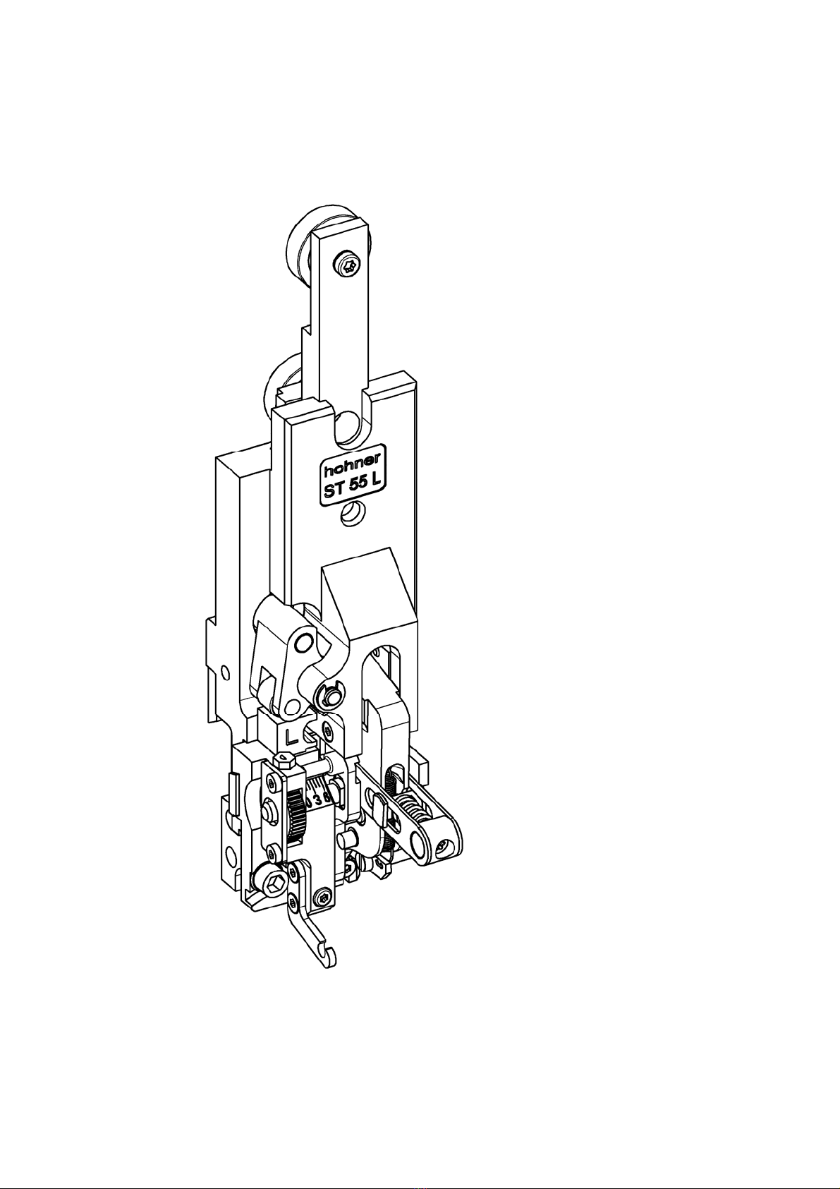
2 DESCRIPTION OF THE STITCHING HEAD 9
2.1 General overview ......................................................................................................... 10
2.2 Conformity ................................................................................................................... 10
2.3 Marking and type plate................................................................................................. 10
2.4 Technical data.............................................................................................................. 10
2.4.1 Normal stitch .............................................................................................................. 11
2.5 Dimensional sheet ....................................................................................................... 13
2.6 Outfitting of the stitching head ..................................................................................... 13
2.6.1 Basic features ............................................................................................................13
2.6.2 Additional equipment.................................................................................................. 13
3 OPERATION 14
3.1 Installation of the stitching head................................................................................... 15
3.1.1 Clamping the stitching head....................................................................................... 15
3.1.1.1 Lateral adjustment of the stitching head........................................................ 15
3.1.2 Fitting the wire guide .................................................................................................. 17
3.1.3 Fitting the clincher box ............................................................................................... 19
3.1.4 Fitting the wire guide hose ......................................................................................... 21
3.1.5 Fitting the hose guide................................................................................................. 21
3.2 Feeding the stitching wire ............................................................................................ 23
3.3 Removing the stitching wire ......................................................................................... 23
3.4 Straighten the stitching wire......................................................................................... 25
3.4.1 Setting the leg length of the stitch .............................................................................. 27
3.5 Setting the former ........................................................................................................ 29
3.6 Spine centering parts ................................................................................................... 31
3.6.1 Installing the holding down device ............................................................................. 31
3.6.2 Adjusting the holding down device............................................................................. 31
4 SERVICING 32
4.1 Lubrication ................................................................................................................... 33
4.1.1 Lubricants .................................................................................................................. 33
4.1.2 Lubrication plan..........................................................................................................33
4.2 Installation and replacement of parts ........................................................................... 34
4.2.1 Replacing the former.................................................................................................. 35
4.2.2 Replacing the driver ................................................................................................... 37
4.2.3 Replacing the bender ................................................................................................. 37
4.2.4 Replacing the knife..................................................................................................... 39
4.2.4.1 Rotating/Changing the flat knife .................................................................... 39
4.2.4.2 Replacing the circular knife ........................................................................... 39
4.2.4.3 Adjusting the circular knife............................................................................. 39
4.2.5 Replacing the clincher................................................................................................ 41

List of Contents
Hohner Maschinenbau GmbH ST 55 L 5
5 FAULTS 42
5.1 Causes and elimination of faults.................................................................................. 42
SPARE PARTS LIST E1

Safety Information
ST 55 L Hohner Maschinenbau GmbH
6
1 Safety Information
1.1 Purpose of this document
This document will inform the operator of the Stitching Head ST 55 L of the following:
•The safety symbols and signs
•The packing of the machine and its transportation
•The function and operation of the machine
•Commissioning the machine
•The elimination of faults which arise
•Servicing
Familiarity with this Operating Manual is thus a prerequisite for the safe and correct operation of
the stitching head. It must be read carefully by the operator before the machine is commissioned.
Keep the manual safely in a place where it is readily available and which is close to hand for
persons working on the machine.
1.2 The operator
The Stitching Head ST 55 L must only be operated by trained personnel.
Training will be undertaken by the manufacturer or by persons who have been authorised by the
manufacturer to undertake such training.
1.3 Safety symbols and the displays that have been used
This symbol indicates immediate danger to the life or health of
persons in the immediate vicinity of the machine.
Non-observance of dangers which are so indicated can have grave
consequences and can cause serious damage to health, or may even to
lead to deaths.
This symbol indicates that a potentially dangerous situation has
arisen.
Non-observance of dangers which are so indicated can lead to slight injuries
to persons or damage to equipment.
This symbol indicates that tips on how to use the machine or
particularly useful information are available.
These will help you to use all of the functions of the machine in an optimal
manner.
-This symbol requires you to take action.
•This sign serves as a symbol for listing items.

Safety Information
Hohner Maschinenbau GmbH ST 55 L 7
1.4 Obligation and liability
The Stitching Head ST 55 L has been built according to state-of-the art technology under
observance of all the recognised safety regulations. However, dangers to life and limb of the user
or third parties and damage to the system or other material assets can still occur during use.
The stitching head should only be used,
• for the purpose for which it was designed
• when it is in a perfect technical condition.
Faults which could reduce levels of safety when using the machine must be eliminated
immediately.
Warranties and liability on the part of the manufacturer are fundamentally covered by the
regulations laid down in our ”General sales and delivery conditions”.
Warranty claims will only be valid if the number label is affixed
(number label on stitching head housing).
1.5 Correct use
The Stitching Head ST 55 L is designed exclusively for binding brochures and leaflets or similar
items.
Any use of the machine contrary to that described above is forbidden, since incorrect use of the
machine can present a danger.
1.6 Organisational measures
The user of machine is required to provide the required personal safety equipment. All existing
safety devices should be checked regularly.
1.7 Safety and protective devices
All safety and protective devices must be correctly attached to the machine and should be in full
working order before every start-up of the machine and Stitching Head ST 55 L.
Safety and protective devices may only be removed:
• After the machine has come to a standstill and
• As security against the machine starting up again.
1.8 Non-formal safety measures
The Operating Manual must be kept so that it is permanently at hand at the machine with
Stitching Head ST 55 L. There are also generally valid local regulations concerning accident
prevention and environmental protection measures which should be made available and observed
in addition to those described in the Operating Instructions.
All safety and danger signs on the machine should be maintained in a legible condition and should
be renewed where necessary.
1.9 Staff training
Only trained and instructed personnel may install, operate, set and maintain the stitching head.

Safety Information
ST 55 L Hohner Maschinenbau GmbH
8
1.10 Parts of the equipment which are particularly dangerous
There is a risk of injury in the area of moving parts of the stitching head.
1.11 Maintenance and repair work, elimination of faults
Undertake the required setting, servicing and inspection work on schedule.
The machine may only be operated in cycle mode during all servicing, inspection and repair work
on the Stitching Head ST 55 L.
Always make absolutely sure that the machine is only being operated by one person in order
to avoid any influence to the machine by any other persons.
1.12 Structural modifications to the stitching head
Changes to the stitching head, additions or modifications may only be undertaken with the
manufacturer's permission.
1.13 Cleaning the machine and the disposal of waste products
The functionality of the stitching head and perfect processing of the product can only be
guaranteed over a prolonged period of time if the stitching head is regularly cleaned and
maintained in accordance with the standard methods of mechanical engineering.
In this regard, particular attention should be paid to the regular removal of trimmed paper
residue and paper dust, as these can result in jamming of the stitching head or increased
wear.
Substances and materials used (e.g. solvents and lubricants) must be handled correctly and
disposed of in an environmentally friendly manner.

Description of the Stitching Head
Hohner Maschinenbau GmbH ST 55 L 9
2 Description of the Stitching Head
Fig. 1

Description of the Stitching Head
ST 55 L Hohner Maschinenbau GmbH
10
2.1 General overview
- Fig. 1 -
2.2 Conformity
Please observe the document attached:
”EC Declaration of Incorporation according to the EC Machinery Directive 2006 / 42 / EC”
2.3 Marking and type plate
The type plate is located at the front of the stitching head.
The stitching head serial number is located on an adhesive plate on the right side of the housing.
2.4 Technical data
Net weight of the stitching head 1,1 kg / 2.42 lbs
Quality of the stitching wire Only use perfect quality classes, in normal or
steel strength as required. Pay attention to
abrasion resistance, as heavy abrasion will clog
the wire-guidance parts.

Description of the Stitching Head
Hohner Maschinenbau GmbH ST 55 L 11
2.4.1 Normal stitch
Standard - L6 - - L 8 -
Wire stitch dimensions
Max. stitch thickness
Round stitching wire
No. 24 - 26
Ø 0.60 - 0.50 mm
(Ø 0.024 - 0.020 in.)
Possible distances
between wire stitches and
stitch thicknesses in mm
With holding down device
With centering device
roller

Description of the Stitching Head
ST 55 L Hohner Maschinenbau GmbH
12
Fig. 2

Description of the Stitching Head
Hohner Maschinenbau GmbH ST 55 L 13
Fig. 3
2.5 Dimensional sheet
- Fig. 2 , Fig. 3-
2.6 Outfitting of the stitching head
2.6.1 Basic features
The stitching head is delivered with the following accessories:
DESCRIPTION ORDER NUMBER
Distance sleeve (80 mm) 31 55 414
Clincher box adjustment gauge 31 64 448
Torsion spring 39 55 345
Allen key with T-handle SW4 x 150 46 00 033
Torx screwdriver T10 46 00 044
Torx screwdriver T20 46 00 045
Holding down set, complete 99 55 455
Wire clamp, complete 99 55 690
Clincher box, complete 99 55 692
2.6.2 Additional equipment
The following optional accessories are available:
DESCRIPTION ORDER NUMBER
Tenon block rail – spacing 80 31 59 014
Terminal strip for clincher box spacing 80 31 59 414
Wire hose (660 mm) 31 55 678
Kit of interchange parts - L8 - 99 55 655
Hose guide, complete 99 55 680
Socket block, complete 99 55 694
Centre of wire stitch

Operation
ST 55 L Hohner Maschinenbau GmbH
14
3 Operation
Fig. 4

Operation
Hohner Maschinenbau GmbH ST 55 L 15
3.1 Installation of the stitching head
3.1.1 Clamping the stitching head
- Fig. 4 -
The stitching head is held by a tenon block which is inserted into the stitching head mounting on
the machine.
- Loosen tenon block with Allen key SW4 . Unscrew the screw as far as possible.
- Insert the stitching head with tenon block (top tilted to the front) in the stitching head mounting
The two ball bearings on the stitching head must be located in the guides of the lifting bar.
- Fix stitching head in stitching head mounting by tightening the tenon block with the Allen key.
The stitching unit is equipped with a basic mounting position. The stitching head with its slides and
the ball bearings is fastened in the basic mounting position with a mounting pin .
- The mounting pin should only be used for assembly and disassembly and must be removed
before the stitching head is put into operation. Preserve the mounting pin carefully.
- Lead the mounting pin through the stitching head housing and the two slides in order to fasten
the basic mounting position before removing the stitching head.
3.1.1.1 Lateral adjustment of the stitching head
- Fig. 4 -
The center of the wire formed parts within the stitching head must be set to the desired stitching
position for the wire stitch by lateral adjustment.
- Loosen the tenon block with the Allen key .
- Move the stitching head sideways, until the desired position is reached.
- Fix the tenon block in the stitching head mounting with the Allen key.

Operation
ST 55 L Hohner Maschinenbau GmbH
16
Fig. 5

Operation
Hohner Maschinenbau GmbH ST 55 L 17
3.1.2 Fitting the wire guide
- Fig. 5 -
- First remove the fastening screws , the clincher box and the tenon block .
- Push the tenon block in the crosshead from the back.
- Place the clincher box on the crosshead from the front and make sure that the tappet is
positioned in the corresponding stroke bar.
- Fasten the clincher box with the tenon block in the crosshead by means of the fastening
screws .
More details are given in the stitching unit operating instructions.

Operation
ST 55 L Hohner Maschinenbau GmbH
18
Fig. 6
Fig.7

Operation
Hohner Maschinenbau GmbH ST 55 L 19
3.1.3 Fitting the clincher box
- Fig. 6 -
The centre of the bender inside the stitching head must be precisely aligned to the centre of the
clincher box.
- Loosen the clamping screws .
- Move clincher box until it is precisely aligned with the centre of the bender.
- Fasten clincher box by tightening the clamping screws.
Using the clincher box setting gauge
- Fig. 7 -
- Remove former (see page 35).
- Place gauge on former locating pin and turn downward against stopper. The clincher box
can be exactly aligned in this position when the gauge is aligned with the scale marks on the
clincher box.
- Tighten clamping screws and remove gauge .
- Refit former.

Operation
ST 55 L Hohner Maschinenbau GmbH
20
Fig. 8
Fig. 9
Transport box
Table of contents
Other Hohner Sewing Machine Accessories manuals